
![]()
OPERATING MANUAL
Handset Wired
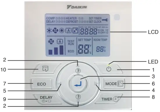
BRC51D64/65 Remote Controller Indication
OPERATING INSTRUCTION
 Button
• Press once to start the air conditioner unit.
• Press again to stop the unit. CAUTION
In the case when the ON/OFF key is pressed immediately after the operation is stopped, the unit will not restart until 3 minutes later to protect the compressor. and
and  Button
• Press theor button to increase or decrease the set temperature.
• Pressing ECO and button simultaneously to toggle the temperature setting between °C and °F.
 Button
• Press the button to save the selection of choices during the setting. Button
• Press thebutton to move to the right choices of function. Button
• Pressthe button to move to the left choices of function.- MODE
 Button
• Press the MODE button to select the type of operating mode.
• For the cooling model, the available modes are: COOL , and FAN
  .
.
• For the heat pump model, the available modes are: COOL , FAN, HEAT  , and AUTO
  .
. - ECO Mode
• Press the ECO button to select the energy-saving function. This option is available for COOL, HEAT, and AUTO modes.
• Press the ECO button continuously 3 seconds to activate or inactivate the Key Lock function. Only the button can be pressed during Key Lock activation.
 - TIMER
 Button NOTE
• Idle 10 seconds to exit the clock setting.
• The clock setting is in 24-hour clock.
A) To set the clock – Press TIMER and button simultaneously for 3 seconds.
a. Hour will blink. b. Press
  the button to change the Hour.
c. Press thebutton to confirm the Hour, then the Minute will blink. d. Press the button to change the Minute.
e. Pressthe button to confirm the Minute, then “MON” will blink.
f. Press the button to change the Day.
g. Press thebutton to confirm the Day.
B) ON/OFF Timer Setting – Daily Timer Setting
a. Continuously press the TIMERbutton for 3 seconds.
b. ON Timer 1 Setting
I. “MON” will blink.
II. Usethe button to select the Day and press the button to confirm the Day.
III. Hour will blink. Usethe button to toggle between Hour and Minute. Press the button to change the Hour and Minute.
Press thebutton to confirm the setting.
IV. Repeat Steps II to III for the timer setting of other days.
c. ON Timer 2 Setting
I. Press the TIMERbutton again to enter the ON Timer 2 setting, then “MON” will blink.
II. Usethe button to select the Day and press the button to confirm the Day.
III. Hour will blink. Press the button to change the Hour.
Pressthe button to confirm the Hour, then the Minute will blink.
IV. Repeat Steps II to III for the timer setting of other days.
d. OFF Timer 1 Setting
I. Press the TIMERbutton again to enter the OFF Timer 1 setting, then “MON” will blink.
II. Usethe button to select the Day and press the button to confirm the Day.
III. Hour will blink. Press the button to change the Hour.
Press thebutton to confirm the Hour, then the Minute will blink.
IV. Repeat Steps II to III for the timer setting of other days.
e. OFF Timer 2 Setting
I. Press the TIMERbutton again to enter the OFF Timer 2 setting, then “MON” will blink.
II. Usethe button to select the Day and press the button to confirm the Day.
III. Hour will blink. Press the button to change the Hour.
Press thebutton to confirm the Hour, then the Minute will blink.
IV. Repeat Steps II to III for the timer setting of other days.
C) Activation of ON/OFF Timer
a. Press the TIMERbutton to activate On Timer. ON 1 will blink.
b. Press thebutton for navigation of On Timer selection. c. Press the button to confirm the selection, then OFF 1 will blink.
d. Press thebutton for navigation of Off Timer selection. e. Press the button to confirm the selection and exit. NOTE
• It is not advisable to set ON TIMER and OFF TIMER to have same values.
• Shall these occur, the effective timer will be treated with priority as stated in table below:Priority Timer 1 (Highest) ON TIMER 2 2 OFF TIMER 2 3 ON TIMER 1 4 (Lowest) OFF TIMER 1 - Button
• Pressthe button once will activate the delay timer function for 1 hour. An indicator will show on the LCD. All the set timers will be overridden.
• Press the same button again will increase the delay by an interval of 1 hour (maximum 4 hours delay) • After the delay timer is completed, the delay timer function is deactivated, the indicator is turned OFF and the unit is turned OFF. All the set timers will be resumed.
  Button (Heater Function)
• Continuously press for 3 seconds to enter Auxiliary Electric Heater selection. HEATER 1 will blink.
• Pressthe button for navigation of Auxiliary Electric Heater selection. • Press the button to confirm the selection and exit. NOTE
If any button is not pressed within 10 seconds, it will exit the Auxiliary Electric Heater selection.- Test Run Function
• Continuously press for 3 seconds the ECO button andbutton to test run the unit.
 b. Press
  d. Press
  Press
Press  Press
Press  Press
Press  Press
Press 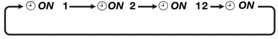 c. Press the
 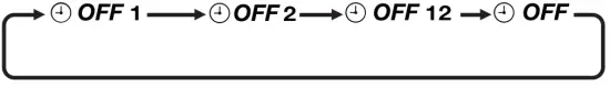 e. Press the
  • After the delay timer is completed, the delay timer function is deactivated, the indicator is turned OFF and the unit is turned OFF. All the set timers will be resumed.
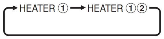 • Press the
 ERROR INDICATOR
![]() NOTE
NOTE
The LED will blink if an error occurred.
If there is any abnormal condition detected, the BRC51D64/65 controller will blink the error code. The format for the error code will be as follows:
| E01 | Require manual reset | El 9 | Indoor coil sensor 4 short |
| E02 | Compressor 1 high temperature (overload) | E20 | Indoor coil sensor 1 open |
| E03 | Compressor 2 high temperature (overload) | E21 | Indoor coil sensor 2 open |
| E04 | Compressor 3 high temperature (overload) | E22 | Indoor coil sensor 3 open |
| E05 | Compressor 4 high temperature (overload) | E23 | Indoor coil sensor 4 open |
| E06 | Compressor 1 high-pressure trip/contact open | E24 | Outdoor coil sensor 1 short |
| E07 | Compressor 2 high-pressure trip / contact open | E25 | Outdoor coil sensor 2 short |
| E08 | Compressor 3 high-pressure trip/contact open | E26 | Outdoor coil sensor 3 short |
| E09 | Compressor 4 high-pressure trip / contact open | E27 | Outdoor coil sensor 4 short |
| El 0 | Compressor 1 trip / low R-22 / outdoor abnormal | E28 | Outdoor coil sensor 1 open |
| Ell | Compressor 2 trip / low R-22 / outdoor abnormal | E29 | Outdoor coil sensor 2 open |
| El 2 | Compressor 3 trip / low R-22 / outdoor abnormal | E30 | Outdoor coil sensor 3 open |
| El 3 | Compressor 4 trip / low R-22 / outdoor abnormal | E31 | Outdoor coil sensor 4 open |
| El 4 | Room sensor short | E32 | Compressor 1 de-ice |
| El 5 | Room sensor open | E33 | Compressor 2 de-ice |
| El 6 | Indoor coil sensor 1 short | E34 | Compressor 3 de-ice |
| El 7 | Indoor coil sensor 2 short | E35 | Compressor 4 de-ice |
| El 8 | Indoor coil sensor 3 short |
INSTALLATION
![]() NOTE
NOTE
Installation and maintenance should be performed by quality ed persons who are familiar with local codes and regulations and have experience with this type of appliance.
- Accessories
The following accessories are included together with this manual. If any part is missing, contact your dealer immediately.
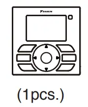
1.1 Remote controller
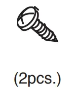
1.2 Screw (2 pieces)Screw Handset 

- Step-by-step guide
2.1 Remove the upper case.
Insert a screwdriver in the recess of the lower case to remove the upper case (2 points).
A remote controller printed-circuit board is installed on the uppercase. Be careful not to damage the printed-circuit board with the screwdriver.
Be careful not to let dust or moisture touch the printed circuit board. Insert and twist the screwdriver ‘LIGHTLY’ for removal.
2.2 Location where the wiring will enter the remote controller.
Top center outlet Cut the plastic at the notched area and remove any remaining burrs.
2.3 Installation procedure for the lower case.
When wiring the remote controller through the top center or rear access points, attachment of the wire to the lower case is required before it is wall mounted. Closely follow the wiring procedures.
Wall installation NOTE
NOTE
• Install the control on and at the surface only.
• To prevent deformation of the lower case, avoid over-tightening the installation screws.
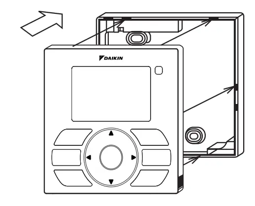
2.4 Install the upper case.
• Align the upper case with tabs of the lower case (6 points), insert and install the upper case.
• Install the wiring with care to prevent pinching.
• Peel off the protective membrane which overlays the upper case.
 Insert and twist the screwdriver ‘LIGHTLY’ for removal.
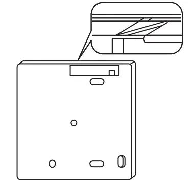 Cut the plastic at the notched area and remove any remaining burrs.
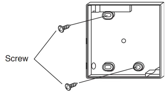
OM-BRC51D-1117(1)-DAIKIN
Part No.: R08019047479A