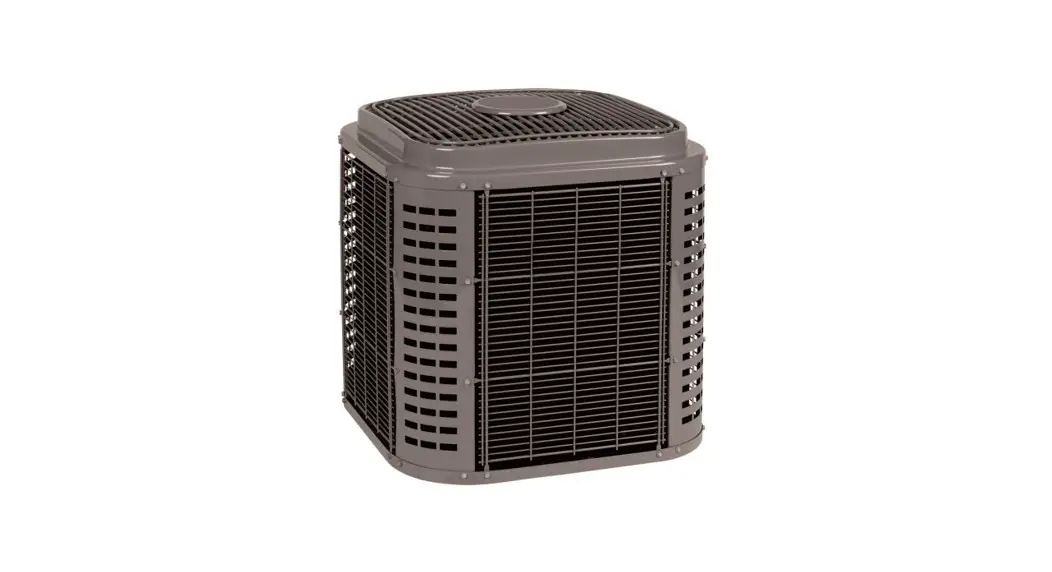
![]() C4H7T 2 Stage Heat Pump with R-410A Refrigerant 2 To 5 Tons
C4H7T 2 Stage Heat Pump with R-410A Refrigerant 2 To 5 Tons
Owner’s Manual
C4H7T 2 Stage Heat Pump with R-410A Refrigerant 2 To 5 Tons
This unit has been designed utilizing R-410A refrigerant. The environmentally sound refrigerant allows you to make a responsible decision in the protection of the earth’s ozone layer.
NOTE: Ratings contained in this document are subject to change at any time. Always refer to the AHRI directory (www.ahridirectory.org) for the most up-to-date ratings information.
Product Specifications
Industry leading Features / Benefits Efficiency
- Up to 17.0 SEER2 (18.5 SEER) / Up to 13.0 EER2 (14 EER) / Up to 8.1 HSPF2 (9.5 HSPF)
- Indoor air quality accessories available
Sound
- Sound level as low as 69 dBA
Comfort
- System supports Thermidistat or standard 2-stage thermostat controls
Reliability
- R-410A refrigerant – environmentally sound, won’t deplete the ozone layer and low lifetime service cost.
- Front-seating service valves
- 2-stage scroll compressor
- Internal pressure relief valve
- Internal thermal overload
- Loss of charge switch
- Filter drier
- Balanced refrigeration system for maximum reliability
Durability
- Protection Package: Solid, Durable sheet metal construction
- Post-painted cabinet finish over galvanized steel
Applications
- Long-line – up to 250 feet (76.2 m) total equivalent length, up to 200 feet (60.96 m) condenser above evaporator, or up to 80 ft. (24.38 m) evaporator above condenser (See Longline Guide for more information.)
- Low ambient cooling (down to 0°F / -17.8°C ) with approved low ambient accessory kits.
STANDARD FEATURES
FEATURES | Unit Size | |||
| R-410A Refrigerant | X | X | X | X |
| Maximum SEER2 (SEER) Rating* | 17.0 (18.5) | 17.0 (17.5) | 17.0 (18.0) | 16.0 (17.0) |
| 2-Stage Scroll Compressor | X | X | X | X |
| Low Ambient Cooling Capability with Approved Kits | X | X | X | X |
| Crankcase Heater w/Temperature Switch | X | X | X | X |
| Field Installed Filter Drier | X | X | X | X |
| Front Seating Service Valves | X | X | X | X |
| Internal Pressure Relief Valve | X | X | X | X |
| Internal Thermal Overload | X | X | X | X |
| Long Line capability | X | X | X | X |
| Loss of Charge Switch | X | X | X | X |
| High Pressure Switch | X | X | X | X |
| Compressor Sound Blanket | X | X | X | X |
MODEL NUMBER NOMENCLATURE
| C | 4 | H | 7 | T | 18 | A | K | A | A | A |
| Brand C = Mainline Comfortmaker | Refrigerant 4 = R-410A | Type H = HP | SEER2 7= 17 SEER2 | OD Design Type T= Two-Stage | Nominal Capacity 24 = 2 Tons 36 = 3 Tons 48 = 4 Tons 60 = 5 Tons | Feature A = Standard | Voltage K = 208/230-60-1 | Special Feature A = Standard | Region A = Standard HP | Major Series A = Initial |
CATALOG ORDERING NUMBERS
| Size | Model Ordering Number |
| 24 | C4H7T24AKAAA |
| 36 | C4H7T36AKAAA |
| 48 | C4H7T48AKAAA |
| 60 | C4H7T60AKAAA |
For AHRI ratings certificates, please refer to the AHRI directory www.ahridirectory.org
Additional ratings and system combinations can be accessed via the Ratings Database here: Comfortmaker Ratings![]() Use of the AHRI Certified TM Mark indicates a manufacturer’s participation in the program For verification of certification for individual products, go to www.ahridirectory.org.
Use of the AHRI Certified TM Mark indicates a manufacturer’s participation in the program For verification of certification for individual products, go to www.ahridirectory.org. ![]()
![]() This product has been designed and manufactured to meet Energy Star
This product has been designed and manufactured to meet Energy Star ![]() criteria for energy efficiency when matched with appropriate coil components. However, proper refrigerant charge and proper air flow are critica to achieve rated capacity and efficiency. Installation of this product should follow all manufacturing refrigeran. charging and air flow instructions. Failure to confirm proper charge and air flow may reduce energy efficiency and shorten equipment life.
criteria for energy efficiency when matched with appropriate coil components. However, proper refrigerant charge and proper air flow are critica to achieve rated capacity and efficiency. Installation of this product should follow all manufacturing refrigeran. charging and air flow instructions. Failure to confirm proper charge and air flow may reduce energy efficiency and shorten equipment life.
C4H7T: Product Specifications
REFRIGERANT PIPING LENGTH LIMITATIONS
Liquid Line Sizing and Maximum Total Equivalent Lengths{ for Cooling Only Systems with R-410A
Refrigerant:
The maximum allowable length of a residential split system depends on the liquid line diameter and vertical separation between indoor and outdoor
units.
See Table below for liquid line sizing and maximum lengths :
Table 1 – Maximum Total Equivalent Length
Outdoor Unit BELOW Indoor Unit
| Size | Liquid Line Connection | Liquid Line Diam. w/TXV | HP with R-410A Refrigerant Maximum Total Equivalent Length†: Outdoor unit BELOW Indoor Vertical Separation ft (m) | ||||||||
| 0-5 (0-1.5) | 6-10 (1.8-3.0) | 11-20 (3.4-6.1) | 21-30 (6.4-9.1) | 31-40 (9.4-12.2) | 41-50 (12.5-15.2) | 51-60 (15.5-18.3) | 61-70 (18.6-21.3) | 71-80 (21.6-24.4) | |||
| 24 | 3/8 | 1/4 | 75 | 75 | 75 | 50 | 50 | — | — | — | — |
| 5/16 | 250* | 250* | 250* | 250* | 250* | 225* | 175 | 125 | 100 | ||
| 3/8 | 250* | 250* | 250* | 250* | 250* | 250* | 250* | 250* | 250* | ||
| 36 | 3/8 | 5/16 | 175 | 150 | 150 | 100 | 100 | 100 | 75 | — | — |
| 3//8 | 250* | 250* | 250* | 250* | 250* | 250* | 250* | 250* | 250* | ||
| 48 | 3/8 | 3/8 | 250* | 250* | 250* | 250* | 250* | 250* | 230 | 160 | — |
| 60 | 3/8 | 3/8 | 250* | 250* | 250* | 225* | 190 | 150 | 110 | — | — |
* Maximum actual length not to exceed 200 ft (61 m)
†Total equivalent length accounts for losses due to elbows or fitting. See the Long Line Guideline for details.
— = outside acceptable range
Table 2 – Maximum Total Equivalent Length
Outdoor Unit ABOVE Indoor Unit
| Size | Liquid Line Connection | Liquid Line Diam. w/TXV | HP with R-410A Refrigerant Maximum Total Equivalent Length†: Outdoor unit ABOVE Indoor Vertical Separation ft (m) | |||||||
| 25 (7.6) | 26-50 (7.9-15.2) | 51-75 (15.5-22.9) | 76-100 (23.2-30.5) | 101-125 (30.8-38.1) | 126-150 (38.4-45.7) | 151-175 (46.0-53.3) | 176-200 (53.6-61.0) | |||
| 24 | 3/8 | 1/4 | 100 | 125 | 175 | 200 | 225* | 250* | 250* | 250* |
| 5/16 | 250* | 250* | 250* | 250* | 250* | 250* | 250* | 250* | ||
| 3/8 | 250* | 250* | 250* | 250* | 250* | 250* | 250* | 250* | ||
| 36 | 3/8 | 5/16 | 225* | 250* | 250* | 250* | 250* | 250* | 250* | 250* |
| 3/8 | 250* | 250* | 250* | 250* | 250* | 250* | 250* | 250* | ||
| 48 | 3/8 | 3/8 | 250* | 250* | 250* | 250* | 250* | 250* | 250* | 250* |
| 60 | 3/8 | 3/8 | 250* | 250* | 250* | 250* | 250* | 250* | 250* | 250* |
* Maximum actual length not to exceed 200 ft (61 m)
†Total equivalent length accounts for losses due to elbows or fitting. See the Long Line Guideline for details.
Table 3 – Refrigerant Charge Adjustments
Liquid Line Size | R-410A Charge oz/ft (g/m) |
| 3/8 | 0.60 (17.74) (Factory charge for lineset = 9 oz / 266.16 g) |
| 5/16 | 0.40 (11.83) |
| 1/4 | 0.27 (7.98) |
Units are factory charged for 15 ft (4.6 m) of 3/8” liquid line. The factory charge for 3/8” lineset 9 oz.(266.16 g). When using other length or diameter liquid lines, charge adjustments are required per the chart above.
Charging Formula:
[(Lineset oz/ft x total length) – (factory charge for lineset)] = charge adjustment
Example 1: System has 15 ft of line set using existing 1/4“ liquid line. What charge adjustment is required?
Formula:(.27 oz/ft x 15ft) – (9 oz) = (-4.95) oz.
Net result is to remove 4.95 oz of refrigerant from the system
Example 2: System has 45 ft of existing 5/16” liquid line. What is the charge adjustment?
Formula:(.40 oz/ft. x 45ft) – (9 oz.) = 9 oz.
Net result is to add 9 oz of refrigerant to the system
NOTE: Conditions must be favorable for charging by subcooling method. Indoor temperature must be 70°F to 80°F (21.1°C to 26.7°C), and outdoor temperature must be 70°F to 100°F (21.1°C to 37.8°C). If outside these conditions, adjust charge for long line sets by weigh-in method.
LONG LINE APPLICATIONS
An application is considered Long Line, when the refrigerant level in the system requires the use of accessories to maintain acceptable refrigerant management for systems reliability. See Accessory Usage Guideline table for required accessories. Defining a system as long line depends on the liquid line diameter, actual length of the tubing, and vertical separation between the indoor and outdoor units.
For heat pump systems, the chart below shows when an application is considered Long Line.
Table 4 – HP with R-410A Refrigerant Long Line Description ft (m) Beyond these lengths, a TXV is required
Total Length | Outdoor Unit Above or Below Indoor Unit |
| TXV required beyond 50 ft. (15.2 m) | TXV required beyond 20 ft. (6.1 m) |
Table 5 – HP with R-410A Refrigerant Long Line Description ft (m) (Beyond these lengths, long line accessories are required)
Liquid Line Size | Units On Same Level | Outdoor Below Indoor | Outdoor Above Indoor |
| 1/4 + TXV | No accessories needed within allowed lengths | No accessories needed within allowed lengths | 175 (53.3) |
| 5/16 + TXV | 120 (36.6) | 50 (15.2) vertical or 120 (36.6) total | 120 (36.6) |
| 3/8 + TXV | 80 (24.4) | 35 (10.7) vertical or 80 (24.4) total | 80 (24.4) |
NOTE: See Residential Piping and Long Line Guideline for details
VAPOR LINE SIZING AND COOLING CAPACITY LOSS
Acceptable vapor line diameters provide adequate oil return to the compressor while avoiding excessive capacity loss. The suction line diameters shown in the chart below are acceptable for HP systems with R-410A refrigerant:
| Unit Nominal Size (Btuh) | Maximum Liquid Line Diameters (In. OD) | Vapor Line Diameters (In.) OD | Cooling Capacity Loss (%) Total Equivalent Line Length ft. (m) | ||||||||
| Standard Application | Long Line Application Requires Accessories | ||||||||||
| 26-50 (7.9-15.2) | 51-80 (15.5-24.4) | 81-100 (24.7-30.5) | 101-125 (30.8-38.1) | 126-150 (38.4-45.7) | 151-175 (46.0-50.3) | 176-200 (53.6-60.0) | 201-225 (61.3-68.6) | 226-250 (68.9-76.2) | |||
| 24,000 2-Stage HP with Puron | 3/8 | 5/8 | 0 | 1 | 1 | 2 | 3 | 3 | 4 | 4 | 5 |
| 3/4 | 0 | 1 | 1 | 1 | 1 | 1 | 1 | 1 | 1 | ||
| 36,000 2-Stage HP with Puron | 3/8 | 5/8 | 1 | 2 | 4 | 5 | 6 | 7 | 9 | 10 | 11 |
| 3/4 | 0 | 0 | 1 | 1 | 2 | 2 | 3 | 3 | 4 | ||
| 7/8 | 0 | 0 | — | — | — | — | — | — | — | ||
| 48,000 2-Stage HP with Puron | 3/8 | 3/4 | 1 | 2 | 2 | 3 | 4 | 5 | 6 | 7 | 7 |
| 7/8 | 0 | 1 | 1 | 2 | 2 | 2 | 3 | 3 | 4 | ||
| 1-1/8 | 0 | 0 | — | — | — | — | — | — | — | ||
| 60,000 2-Stage HP with Puron | 3/8 | 3/4 | 1 | 2 | 4 | 5 | 6 | 8 | 9 | 10 | 11 |
| 7/8 | 0 | 1 | 2 | 2 | 3 | 4 | 4 | 55 | |||
| 1-1/8 | 0 | 0 | — | — | — | — | — | — | — | ||
Standard Length = 80 ft. (24.4 m) or less total equivalent length
Applications in this area are long line. Accessories are required as shown recommended on Long Line Application Guidelines
Applications in this area may have height restrictions that limit allowable total equivalent length, when outdoor unit is below indoor unit.
— Applications in this area are not recommended due to insufficient oil return.
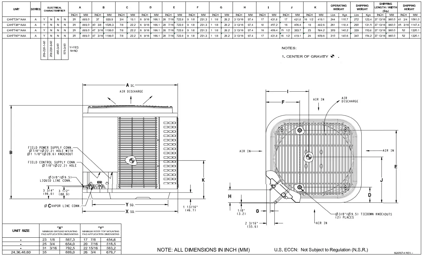
PHYSICAL DATA
| UNIT SIZE | 24 | 36 | 48 | 60 |
| Compressor Type | Scroll | |||
| Refrigerant | R410A | |||
| Control | TXV (R410A Hard Shutoff) | |||
| Charge lb (kg) | 13.29 (6.03) | 14.84 (6.73) | 14.67 (6.65) | 15.45 (7.01) |
| Outdoor Htg Piston # | 46 | 55 | 61 | 67 |
| COND Fan | Propeller Type, Direct Drive | |||
| Air Discharge | Vertical | |||
| Air Qty (CFM) | 3158 | 3158 | 4779 | 5000 |
| Motor HP | 1/12 | 1/12 | 1/4 | 1/4 |
| Motor RPM | 800 | 800 | 800 | 800 |
| COND COIL | ||||
| Face Area (Sq ft) | 22.6 | 25.1 | 30.1 | 30.1 |
| Fins per In. | 20 | 20 | 20 | 20 |
| Rows | 2 | 2 | 2 | 2 |
| Circuits | 9 | 8 | 12 | 12 |
| VALVE CONNECT. (In. ID) | ||||
| Vapor | 3/4 | 7/8 | 7/8 | 7/8 |
| Liquid | 3/8″ | |||
| REFRIGERANT TUBES* (In. OD) | ||||
| Vapor (0-80 Ft Tube Length) | 3/4 | 7/8 | 1 1/8 | 1 1/8 |
| Liquid (0-80 Ft Tube Length) | 3/8″ | |||
*. Units are rated with 25 ft (7.6 m) of lineset length. See Vapor Line Sizing and Cooling Capacity Loss table when using other sizes and lengths of lineset.
Electrical Data
| UNIT SIZE | V/PH | OPER VOLTS* | COMPR | FAN | MCA | MAX FUSE† or CKT BRK AMPS | ||
| MAX | MIN | LRA | RLA | FLA | ||||
| 24 | 208-230/1 | 253 | 197 | 61.0 | 10.9 | 0.50 | 14.1 | 25 |
| 36 | 92.0 | 19.7 | 0.60 | 25.2 | 40 | |||
| 48 | 126.5 | 25.8 | 1.20 | 33.5 | 50 | |||
| 60 | 158.0 | 26.9 | 1.50 | 35.1 | 60 | |||
* Permissible limits of the voltage range at which the unit will operate satisfactorily
† Time-Delay fuse.
FLA- Full Load Amps
LRA – Locked Rotor Amps
MCA- Minimum Circuit Amps
RLA- Rated Load Amps
NOTE: Control circuit is 24-V on all units and requires external power source. Copper wire must be used from service disconnect to unit.
All motors/compressors contain internal overload protection.
Complies with 2010 requirements of ASHRAE Standards 90.1
Sound Power Level
| UNIT SIZE | STANDARD RATING (dBA) | TYPICAL OCTAVE BAND SPECTRUM Without Tone Adjustment (dB) | ||||||
| 125 | 250 | 500 | 1000 | 2000 | 4000 | 8000 | ||
| 24 | 70 – High Stage | 67.5 | 64.9 | 66.0 | 65.1 | 60.9 | 57.3 | 51.4 |
| 69 – Low Stage | 65.2 | 64.7 | 65.5 | 64.4 | 59.7 | 56.7 | 50.5 | |
| 36 | 72 – High Stage | 67.1 | 64.8 | 67.2 | 70.3 | 60.2 | 57.5 | 53.8 |
| 71 – Low Stage | 64.6 | 64.9 | 66.6 | 69.4 | 59.9 | 56.5 | 51.4 | |
| 48 | 73 – High Stage | 69.2 | 68.7 | 70.1 | 67.0 | 61.7 | 58.4 | 52.3 |
| 73 – Low Stage | 67.6 | 67.9 | 70.5 | 69.4 | 61.3 | 58.6 | 56.0 | |
| 60 | 72 – High Stage | 69.2 | 68.0 | 69.1 | 68.4 | 63.9 | 60.0 | 52.6 |
| 72 – Low Stage | 67.9 | 68.4 | 70.0 | 68.2 | 63.8 | 59.6 | 52.9 | |
NOTE: Tested in compliance with AHRI Standard 270 but not listed with AHRI.
Charging Subcooling (TXV-Type Expansion Device)
| UNIT SIZE | REQUIRED SUBCOOLING °F (°C) |
| 24 | 11 (6.1) |
| 36 | 16 (8.9) |
| 48 | 9 (5.0) |
| 60 | 12 (6.7) |
Accessories
| Kit Number | KIT NAME | 24 | 36 | 48 | 60 |
| NASA00201FS | Evaporator Freeze Stat | X | X | X | X |
| NASA001TD | Time Delay Relay | X | X | X | X |
| NASA401LA | Low Ambient | X | X | X | X |
| NASA0010101IK | Isolation Relay | X | X | X | X |
| NASA015SC | Hard Start | X | X | X | X |
| NASA001AC | Cycle Protection | X | X | X | X |
| NASA00201SF | Support Feet | X | X | X | X |
| NASA001LS | Solenoid Valve | X | X | X | X |
| NAEA40501TX | TXV KIT (for use with copper coils) | X | |||
| NAEA40601TX | TXV KIT (for use with copper coils) | X | |||
| NAEA40701TX | TXV KIT (for use with copper coils) | X | X | ||
| NAEB40501TX | TXV KIT (for use with aluminum coils) | X | |||
| NAEB40601TX | TXV KIT (for use with aluminum coils) | X | |||
| NAEB40701TX | TXV KIT (for use with aluminum coils) | X | X | ||
| NASA00106SS | Snow Stand | X | X | X | X |
X = Accessory
ACCESSORY USAGE GUIDELINE
| Accessory | Required for Low Ambient cooling Applications (Below 55°F / 12.8°C) | Required for Long Line Applications* | Required for Sea Coast Applications |
| Compressor Start Assist | Yes | Yes | No |
| Crankcase Heater | Standard | Standard | Standard |
| Evaporator Freeze Thermostat | Yes | No | No |
| Isolation Relay | Yes | No | No |
| Hard Shutoff TXV | Yes (standard w/factory approved indoor unit) | Yes (standard w/factory approved indoor unit) | Yes (standard w/factory approved indoor unit) |
| Liquid Line Solenoid Valve | No | See Residential Piping and Long Line Guideline | No |
| Low-Ambient Control | Yes | No | No |
| Support Feet | Recommended | No | Recommended |
* For tubing line sets between 80 and 200 ft. (24.38 and 60.96 m) and/or 20 ft. (6 m) vertical differential, refer to Residential Piping and Longline Guideline.
Accessory Description and Usage (Listed Alphabetically)
- Compressor Start Assist — Capacitor and Relay
Start capacitor and relay gives a ”hard” boost to compressor motor at each start up.
Usage Guideline:
Required for reciprocating compressors in the following applications:
Long line
Low ambient cooling
Hard shut off expansion valve on indoor coil
Liquid line solenoid on indoor coil
Required for single–phase scroll compressors in the following applications:
Long line
Low ambient cooling
Suggested for all compressors in areas with a history of low voltage problems. - Crankcase Heater
An electric resistance heater which mounts to the base of the compressor to keep the lubricant warm during off cycles. Improves compressor lubrication on restart and minimizes the chance of liquid slugging.
Usage Guideline:
Required in low ambient cooling applications.
Required in long line applications.
Suggested in all commercial applications. - Evaporator Freeze Thermostat
An SPST temperature-actuated switch that stops unit operation when evaporator reaches freeze-up conditions.
Usage Guideline:
Required when low ambient kit has been added. - Liquid-Line Solenoid Valve (LLS)
An electrically operated shutoff valve which stops and starts refrigerant liquid flow in response to compressor operation. It is to be installed at the outdoor unit to control refrigerant off cycle migration in the heating mode.
Usage Guideline:
An LLS is required in all long line heat pump applications to control refrigerant off cycle migration inthe heating mode. See Long Line Guideline.
Suggested for all commercial applications. - Low-Ambient Pressure Switch
A long life pressure switch which is mounted to outdoor unit service valve. It is designed to cycle the outdoor fan motor in order to maintain head pressure within normal operating limits. The control will maintain working head pressure at low-ambient temperatures down to 0°F (-17.8°C) when properly installed.
Usage Guideline:
A Low-Ambient Pressure Switch must be used when cooling operation is used at outdoor temperatures below 55°F (12.8°C). - Support Feet
Four or five stick–on plastic feet that raise the unit 4 in. (101.6 mm) above the mounting pad. This allows sand, dirt, and other debris to be flushed from the unit base, minimizing corrosion.
Usage Guideline:
Suggested in the following applications:
Coastal installations.
Windy areas or where debris is normally circulating.
Rooftop installations.
For improved sound ratings. - Thermostatic Expansion Valve (TXV)
A modulating flow-control valve which meters refrigerant liquid flow rate into the evaporator in response to the superheat of the refrigerant gas leaving the evaporator.
Kit includes valve, adapter tubes, and external equalizer tube. Hard shut off types are available.
NOTE: When using a hard shut off TXV with single phase reciprocating compressors, a Compressor Start Assist Capacitor and Relay is required.
Usage Guideline:
Required to achieve AHRI ratings in certain equipment combinations. Refer to combination ratings.
Hard shut off TXV or LLS required in heat pump long line applications. - Winter Start Control
This control is designed to alleviate nuisance opening of the low-pressure switch by bypassing it for the first 3 minutes of operation.
DIMENSIONS
CLEARANCES
Clearances (various examples)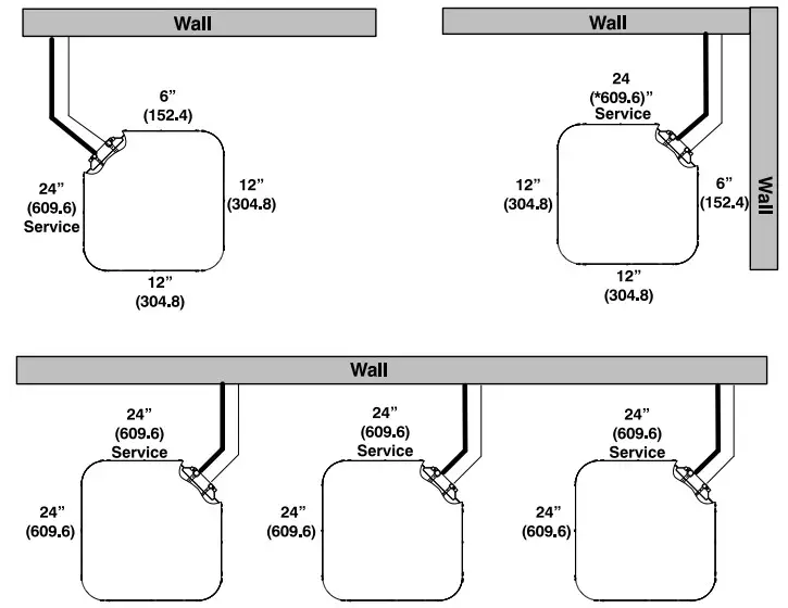 Note: Numbers in ( ) = mm Allow 48″ above unit
IMPORTANT: When installing multiple units in an alcove, roof well, or partially enclosed area, ensure there is adequate ventilation to prevent re-circulation of discharge air.
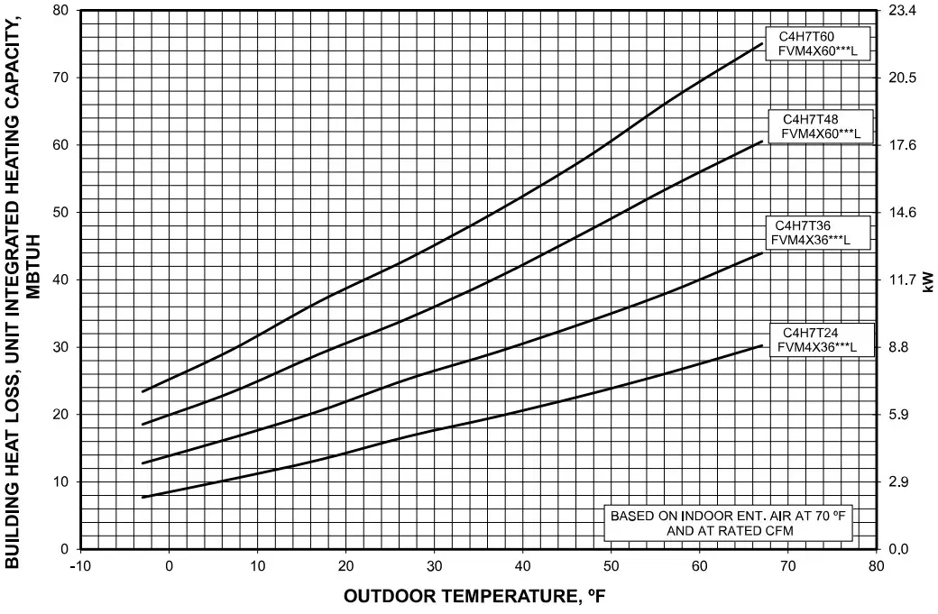
Balance Point Worksheet – High Stage
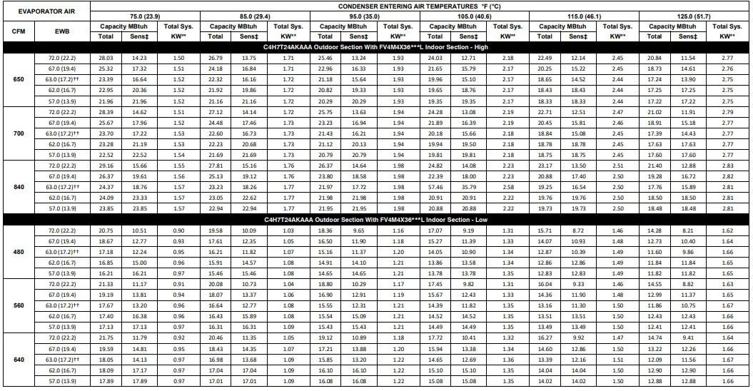
Detailed Cooling Capacities#
 Detailed Cooling Capacities# (Continued)
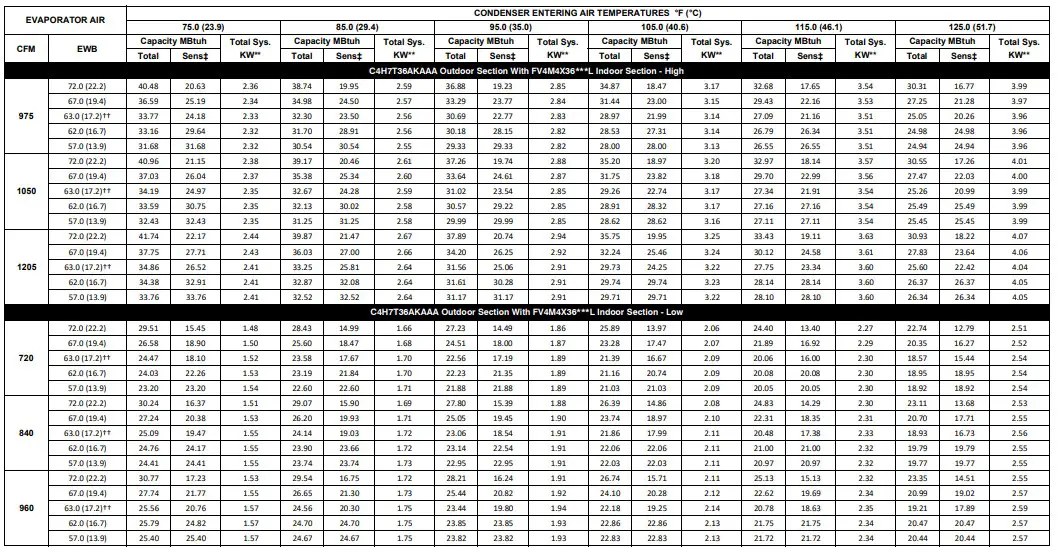

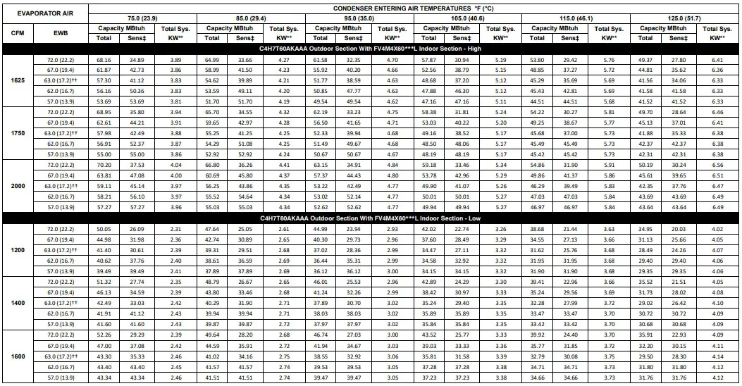 † Total and sensible capacities are net capacities. Blower motor heat has been subtracted.
‡ Sensible capacities shown are based on 80°F (27°C) entering air at the indoor coil. For sensible capacities at other than 80°F (27°C), deduct 835 Btuh
(245 kW) per 1000 CFM (480 L/S) of indoor coil air for each degree below 80°F (27°C), or add 835 Btuh (245 kW) per 1000 CFM (480 L/S) of indoor coil air per degree above 80°F (27°C).
**System kw is total of indoor and outdoor unit kilowatts.
††At TVA rating indoor condition (75°F edb/63°F ewb). All other indoor air temperatures are at 80°F edb.
# Detailed cooling capacities are based on indoor and outdoor unit at the same elevation per AHRI standard 210/240-08. If additional tubing length and/or indoor unit is located above outdoor unit, a slight variation in capacity may occur.
EWB — Entering Wet Bulb
NOTE: When the required data falls between the published data, interpolation may be performed. Extrapolation is not an acceptable practice.
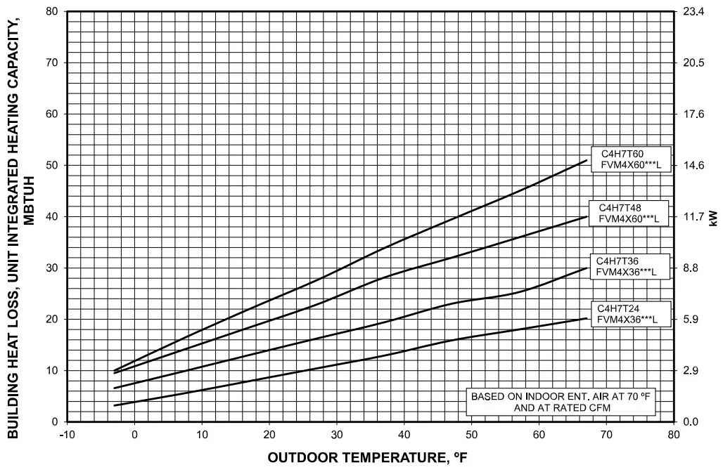
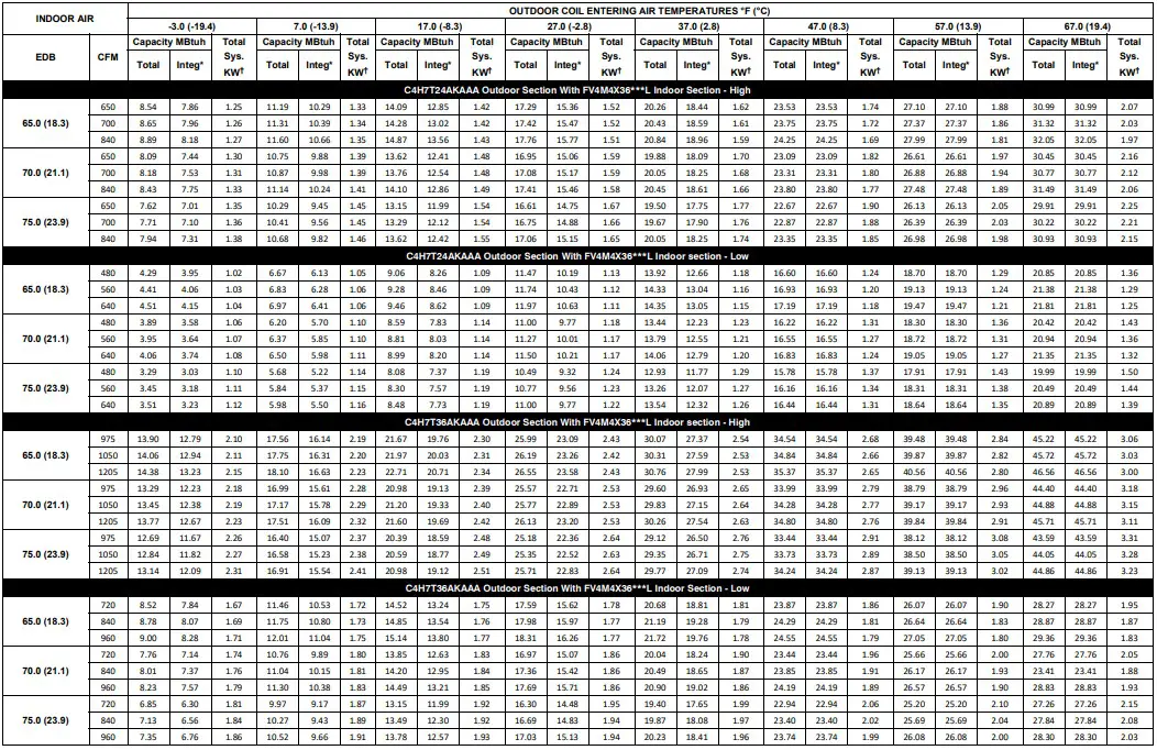
HEAT PUMP HEATING PERFORMANCE
 HEAT PUMP HEATING PERFORMANCE (Continued)
 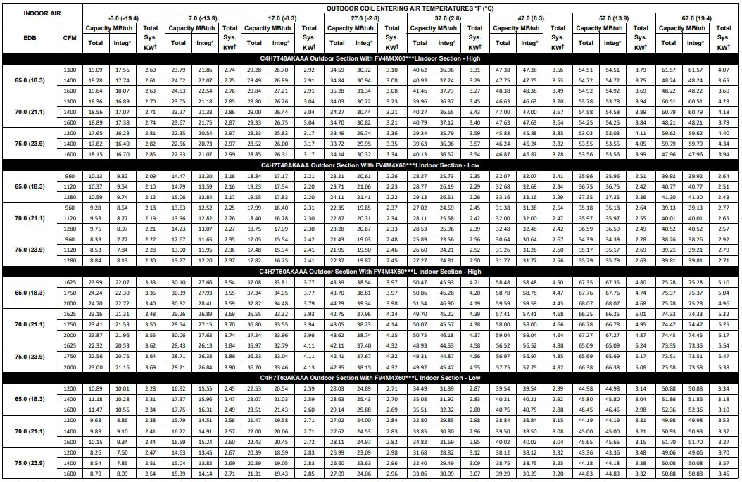 * The Btuh heating capacity values shown are net integrated values from which the defrost effect has been subtracted. The Btuh heating from supplement heaters should be added to those values to obtain total system capacity.
† The kW values include the compressor, outdoor fan motor, and indoor blower motor. The kW from supplement heaters should be added to these values to obtain total system kilowatts.
EDB— Entering Dry Bulb
NOTE: When the required data falls between the published data, interpolation may be performed. Extrapolation is not an acceptable practice.
Guide Specifications
GENERAL
System Description
Outdoor-mounted, air-cooled, split-system heat pump unit suitable for ground or rooftop installation. Unit consists of a hermetic compressor, an air-cooled coil, propeller-type condenser fan, and a control box. Unit will discharge supply air upward as shown on contract drawings. Unit will be used in a refrigeration circuit to match up to a packaged fan coil or coil unit.
Quality Assurance
– Unit will be rated in accordance with the latest edition of AHRI Standard 210.
– Unit will be certified for capacity and efficiency, and listed in the latest AHRI directory.
– Unit construction will comply with latest edition of ANSI/ ASHRAE and with NEC.
– Unit will be constructed in accordance with UL standards and will carry the UL label of approval. Unit will have c-UL approval.
– Unit cabinet will be capable of withstanding Federal Test Method Standard No. 141 (Method 6061) 500-hr salt spray test.
– Air-cooled condenser coils will be leak tested and pressure tested.
– Unit constructed in ISO9001 approved facility.
Delivery, Storage, and Handling
– Unit will be shipped as single package only and is stored and handled per unit manufacturer’s recommendations.
Warranty (for inclusion by specifying engineer)
– U.S. and Canada only.
PRODUCTS
Equipment
– Factory assembled, single piece, air-cooled heat pump unit. Contained within the unit enclosure is all factory wiring, piping, controls, compressor, refrigerant charge R-410A, and special features required prior to field start-up.
Unit Cabinet
– Unit cabinet will be constructed of galvanized steel, bonderized, and coated with post-paint.
– Available with dense wire grille with sheet metal corner posts only.
Fans
Condenser fan will be direct-drive propeller type, discharging air upward.
– Condenser fan motors will be totally enclosed, 1-phase type with class B insulation and permanently lubricated bearings. Shafts will be corrosion resistant.
– Fan blades will be statically and dynamically balanced.
– Condenser fan openings will be equipped with coated steel wire safety guards.
Compressor
– Compressor will be hermetically sealed.
– Compressor will be mounted on rubber vibration isolators.
Condenser Coil
– Condenser coil will be air cooled.
– Coil will be constructed of aluminum fins mechanically bonded to copper or aluminum tubes which are then cleaned, dehydrated, and sealed.
Refrigeration Components
– Refrigeration circuit components will include liquid-line shutoff valve with sweat connections, vapor-line shutoff valve with sweat connections, system charge of R-410A, refrigerant, and compressor oil.
– Unit will be equipped with low and high pressure switch and filter drier for R-410A, refrigerant.
Operating Characteristics
– The capacity of the unit will meet or exceed _____ Btuh at a suction temperature of _____ _F/_C. The power consumption at full load will not exceed _____ kW.
– Combination of the unit and the evaporator or fan coil unit will have a total net cooling capacity of _____ Btuh or greater at conditions of _____ CFM entering air temperature at the evaporator at _____ _F/_C wet bulb and _____ _F/_C dry bulb, and air entering the unit at _____ _F/_C. – The system will have a SEER of _____ Btuh/watt or greater at DOE conditions.
Electrical Requirements
– Nominal unit electrical characteristics will be _____ v, single phase, 60 hz. The unit will be capable of satisfactory operation within voltage limits of _____ v to _____ v.
– Unit electrical power will be single point connection.
– Control circuit will be 24v.
Special Features
– Refer to section of this literature identifying accessories and descriptions for specific features and available enhancements.
System Design Summary
- Intended for outdoor installation with free air inlet and outlet. Outdoor fan external static pressure available is less than 0.01-in. wc.
- Minimum outdoor operating air temperature without low-ambient operation accessory is 55_F (12.8_C).
- The maximum outdoor operating ambient in cooling mode is 125_F (51.67_C) when operating voltage is 230v.
- Minimum outdoor operating air temperature for heating mode is –20_F (–28.9_C).
- Maximum outdoor operating air temperature for heating mode is 66_F (18.9_C).
- For reliable operation, unit should be level in all horizontal planes.
- For interconnecting refrigerant tube lengths greater than 80 ft (23.4 m) and/or elevation differences between indoor and outdoor units greater than 20 ft (6.1 m), consult Residential Piping and Long Line Guideline and Service Manual available from equipment distributor.
- If any refrigerant tubing is buried, provide a 6 in. (152.4 mm) vertical rise to the valve connections at the unit. Refrigerant tubing lengths up to 36
in. (914.4 mm) may be buried without further consideration. Do not bury refrigerant lines longer than 36 in. (914.4 mm). - Use only copper wire for electric connection at unit. Aluminum and clad aluminum are not acceptable for the type of connector provided.
- Do not apply capillary tube indoor coils to these units.
- Factory-supplied filter drier must be installed.
![]() © 2022 Carrier. All rights reserved.
© 2022 Carrier. All rights reserved.
Edition Date: 11/22
A Carrier Company www.GoComfortmaker.com
Catalog No:C4H7T-41-01PD
Replaces: New
Manufacturer reserves the right to change, at any time,
specifications and designs without notice and without obligations.


