LG 14HQ901G-B Flat Panel Digital X-Ray Detector
OPEN SOURCE SOFTWARE NOTICE INFORMATION
To obtain the source code under GPL, LGPL, MPL, and other open source licenses that have the obligations to disclose source code, that is contained in this product, and to access all referred license terms, copyright notices and other relevant documents please visit https://opensource.lge.com.
LG Electronics will also provide open source code to you on CD-ROM for a charge covering the cost of performing such distribution (such as the cost of media, shipping, and handling) upon email request to [email protected].
This offer is valid to anyone in receipt of this information for a period of three years after our last shipment of this product.
ON CLEANING
Recommended Cleaning Chemicals
- Isopropanol 70 %
- Ethanol 70 %
- 0.9 % NaCl solution
- Biospot 500 pm
How to Use Cleaner
- Prior to cleaning, turn off the Detector and remove the power cable.
- Soak a soft cloth in a recommended cleaner, then lightly rub the screen with no more than 1 N of force.
- The cleaner could cause serious damage if it leaks inside the Detector while cleaning.
- Do not use benzene, thinner, acids or alkaline cleaners or other such solvents.
- Cleaning guidelines for Detector must only be carried out by medical professionals (doctors or nurses) and must not be handled by patients.
GENERAL DESCRIPTION
Overview
This model is an x-ray imaging device, a system that can acquire and process X-ray images as digital images. It utilizes amorphous silicon and a high-performance scintillator to ensure sharp high-definition image quality with the resolution of 3.6 lp/mm and the pixel pitches of 140 um. This device is a flat panel based X-ray image acquisition device. This device must be used in conjunction with an operating PC and an X-ray generator. This device can be used for digitizing and transferring X-ray images for radiological diagnosis. The data transmission between the detector and PC can be enabled with a wired (cable) or wireless connection.
Product Components
Basic Accessories
- Detector

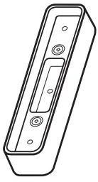
- Battery 2 EA

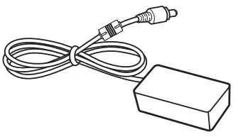
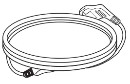
- AC Power Cord for the AC Power Adapter

- Inspection Report

- Owner’s Manual/Regulatory Manual/Calibration Software

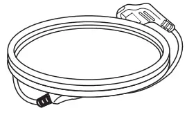
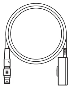
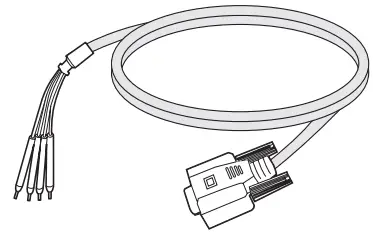
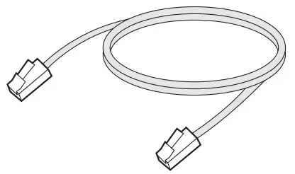
- Main Cable

- AC Power Adapter for Charge

- Battery Charger

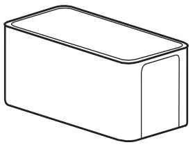
- Control Box

- AC Power Cord for the Control Box

- Main Cable Cradle


Optional Accessories
- Trigger Cable

- LAN Cable

• Some models may not include optional accessories.
![]() CAUTION
CAUTION
- You must use the authorized components as per the specification below. Unauthorized components may cause damage and/or cause the product to malfunction.
| Component | Standard |
| LAN Cable | More than CAT5E Standard |
| Power Cord | US – Approved Medical grade regulation Others – Approved country safety regulation |
- The AC/DC adapters that are being used, with the exception of the upper components, must be supplied by the manufacturer.
NAMES AND FUNCTIONS OF COMPONENTS
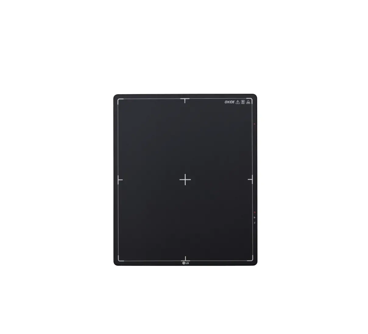
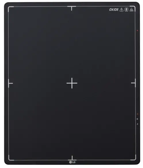
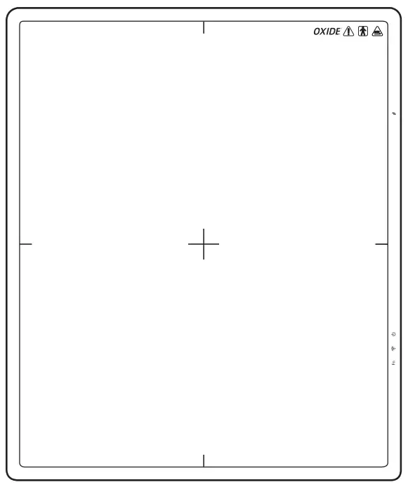
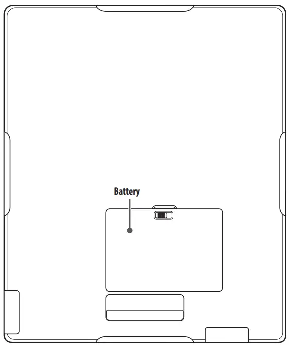
Detector
Front
Back
Side
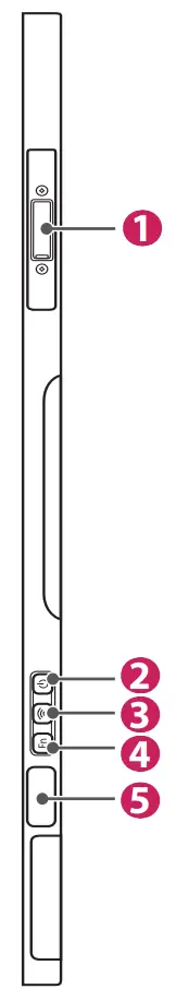
| ❶ | Connection to Main Cable |
| ❷ |
|
| ❸ |
|
| ❹ | Fn
|
| ❺ | OLED Indicator |
Button Information
| Button | Description |
Press the Power button to turn the power on or off.
| |
| Press this button for at least one second to switch between the following connection modes, in respective order: Ethernet/Station/AP mode. | |
| (Function Switch button) | Press this button for at least one second to switch between the following menus, in respective order: Check connection mode, video acquisition, image auto save. The menu is shown on the OLED indicator.
|
![]() NOTE
NOTE
- Press and hold the
 and Fn buttons at the same time for at least ten seconds to restore to factory settings.
LED Indicator
| LED | Description | |
| Displays the power and battery status of the detector. | ||
| Off | Power off | |
| White | Power on | |
| Orange | The battery level is greater than 10 % and less than 30%. | |
| Orange(blinking) | The battery level is less than 10%. | |
| Displays the connection mode status of the detector. | ||
| Green | Ethernet connected | |
| Green(blinking) | Ethernet disconnected | |
| White | Wireless(Station/AP) connected | |
| White(blinking) | Wireless(Station/AP) disconnected | |
| (LED Indicator for Function Switch) | Briefly lights up in green when the Function Switch button is used to change the on/off settings. | |
![]() NOTE
NOTE
- If the LED indicators show the following behaviour, a system error may have occurred. Please contact the manufacturer.
– (White(blinking)) + (Green(blinking)) + Fn (Green(blinking))
OLED Indicator
The OLED indicator displays the information below.
| Connection Mode | Information | ||
| Ethernet | Station | AP | |
 |  |  | Wired/STA/AP – Check Connection Mode (Ethernet/Station/AP). |
 |  |  | Dynamic On/Off – Video Acquisition |
 |  |  | Auto save On/Off (Up to 200 images) – Image Auto save |
![]() NOTE
NOTE
- The information displayed on the OLED indicator will vary depending on the connection mode (Ethernet/Station/AP).
- If left idle for ten seconds after pressing the Fn button, the OLED indicator turns off. When the OLED indicator is turned on again, the starting screen is displayed.
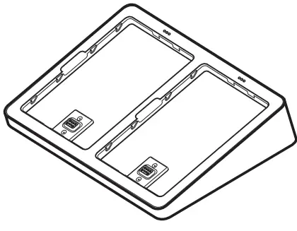
Battery and Battery Charger
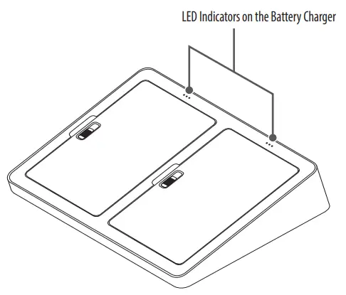
| LED Indicators on the Battery Charger | 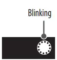 | 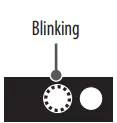 | 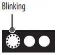 |  |
| Remaining Battery Levels | 0 ~ 30 % | 30 ~ 70 % | 70 ~ 99 % | 100 % |
| Battery Status | On charging | Completion of charging | ||
![]() NOTE
NOTE
- Battery: Lithium ion polymer battery (charging time – Typ. 3 hours)
- Battery Charger: 2-port cradle type
- The remaining battery level and status for each battery can be checked through the LED indicators on the battery charger.
- If the LED indicator does not turn on when charging the battery, it may be a connection error. Please reinstall the battery.
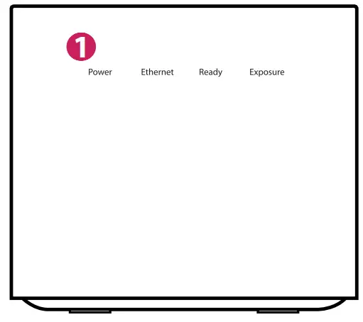
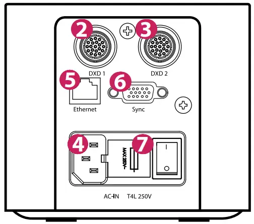
Control Box
Front
Back
| Number | LED Indicator | LED Colour | Description |
| ❶ | Power | Green | Power normal operation |
| Off | Power off (AC power cord no connection or Power error) | ||
| Ethernet | Green | Ethernet normal operation | |
| Green(blinking) | On data communication | ||
| Off | Ethernet disconnected | ||
| Ready | Green | Ready signal from X-ray Generator is active | |
| Off | Ready signal from X-ray Generator is inactive | ||
| Orange(blinking) | Power error | ||
| Exposure | Orange | Exposure signal from X-ray Generator is active | |
| Off | Exposure signal from X-ray Generator is inactive | ||
| Orange(blinking) | Power error |