![]()
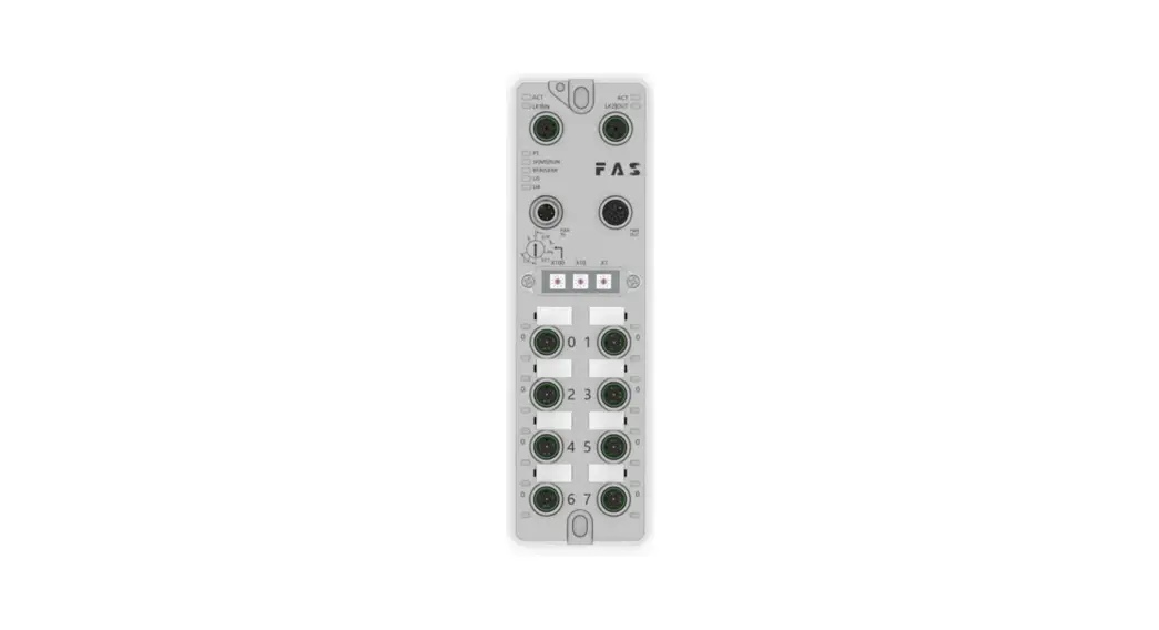
FNI MPL-302-105-M
IP 67 Module User Manual

Notes
1.1. Manual structure
This manual is organized by organization, so the chapters are interconnected. Section 2: Basic Safety Information.
Chapter 3: Getting Started Guide
Chapter 4: Technical data
……
1.2. Typography
The following typographic conventions are used in this manual.
Enumerate
The enumeration is displayed as a list with bullets.
- Entry 1
- Entry 2
Action
Action descriptions are represented by a front triangle.
The result of the action is represented by an arrow.
Action description 1
Action result
Action description 2
Step programs can also be displayed numerically in parentheses.
(1) Step 1
(2) Step 2
Grammar
Number:
Decimal numbers are displayed without additional indicators (eg 123) Hexadecimal numbers are displayed with an additional indicator hex (eg: 00hex ) or with the prefix “0X” (eg: 0x00) Cross-reference
1.3 symbol
Notes
This symbol indicates a general comment.
Notice!
This symbol indicates the most important safety notice.
————————————————– ———
Cross-references indicate where to find additional information on this topic.
1.4. Acronym
FNI FAS Network Interface
I Standard input port
PN Pofinet
ECT EtherCAT
CIE CC_link IEF Basic
EIP Ethernet/IP
EMC Electromagnetic Compatibility
FE functional ground
O Standard output port
1.5. Viewing deviations
The product views and explanations in this manual may deviate from the actual product. They are only left and right solutions
Safety
2.1. Intended use
This manual describes as decentralized input and Precautions! output modules for connection to an industrial network.
2.2.Installation and Startup
Installation and start-up may only be carried out by trained and specialized personnel. A qualified individual is one who is familiar with the installation and operation of the product and has the necessary qualifications to do so. Any damage caused by unauthorized operation or illegal and improper use is not covered by the manufacturer’s warranty. Equipment operators are responsible for ensuring that appropriate safety and accident prevention regulations are followed.
2.3. General Security Notes
Debug and check
Before debugging, you should read the contents of the user manual carefully.
The system cannot be used in applications where the safety of personnel depends on the functionality of the equipment. intended use
The manufacturer’s warranty coverage and limited liability statement do not cover damage caused by:
- Unauthorized tampering
- Improper use
- Owner/operator’s obligations
This device is an EMC Class A product. This device generates RF noise.
The owner/operator must take proper precautions when using this equipment. Use only a power source compatible with this device and connect only approved cables.
Fault
In the event of a defect or equipment malfunction that cannot be corrected, the equipment must be taken out of operation to avoid possible damage from unauthorized use.
Intended use can only be ensured when the enclosure is fully installed.
2.4. Corrosion resistance Precautions!
FNI modules generally have good chemical and oil resistance characteristics. When used in aggressive media (e.g. high concentrations of chemicals, oils, lubricants and coolants (i.e. low water content)), these media must be checked before the corresponding application material compatibility confirm. If the module fails or is damaged due to this corrosive medium, no claim for defects can be claimed
Dangerous voltage
Disconnect all power sources before using the equipment!
Getting Started Guide
3.1. Module overview

| 1 Mounting hole 2 Network port 2 Status indicator 3 Network port 2 4 Power outlet 5 DIP switch 6 Port 1 7 Port 3 | 8 Port 5 9 Port 7 10 Port 6 11 Port 4 12 Port 2 13 Port Status 14 Port 0 | 15 Port Identification Board 16 Power input port 17 Module indicator 18 Network port 1 19 Network port 1 status indicator 20 Ground connection |
3.2. Mechanical connection
The modules are attached using 2 M6 bolts and 2 washers.
Isolation pads are available as accessories.
3.3. Electrical connections
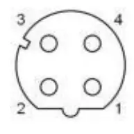
3.3. 1 Power interface(L-code )
Definition of power input port

Definition of power output port

| Pin | Function | Describe |
| 1 | Us+ | +24V |
| 2 | Ua-* | 0V |
| 3 | Us- | 0V |
| 4 | Ua+* | +24V |
| FE | Functional ground* | FE |
Notes:
- If possible, supply sensor/module power and actuator power separately.
Otal current <9A. The total current of all modules is <9A, even when daisy -chaining the actuator powersupply. - The FE connection from the housing to the machine must be low impedance and kept as short as possible.
3.3.2 Network Interface (D-code)
| Pin | Function | |
| 1 | Tx+ | Send data+ |
| 2 | Rx+ | Receive data+ |
| 3 | Tx- | Send data- |
| 4 | Rx- | Receive data- |
Notes:
Unused I/O port sockets must be covered with end caps to meet IP67 rating.
3.3.3
I/O-Port(A-code)
| Pin | Function |
| 1 | +24V,1A |
| 2 | Enter/output |
| 3 | 0V |
| 4 | Enter/output |
| 5 | FE |
Note:
- For digital sensor input, please follow the input guidelines of EN61131-2, Type 2.
- The maximum output current of pins 2 and 4 is 2A. The total current of the module is less than 9A.
- Unused I/O port sockets must be covered with end caps to meet IP67 degree of protection.
Technical data
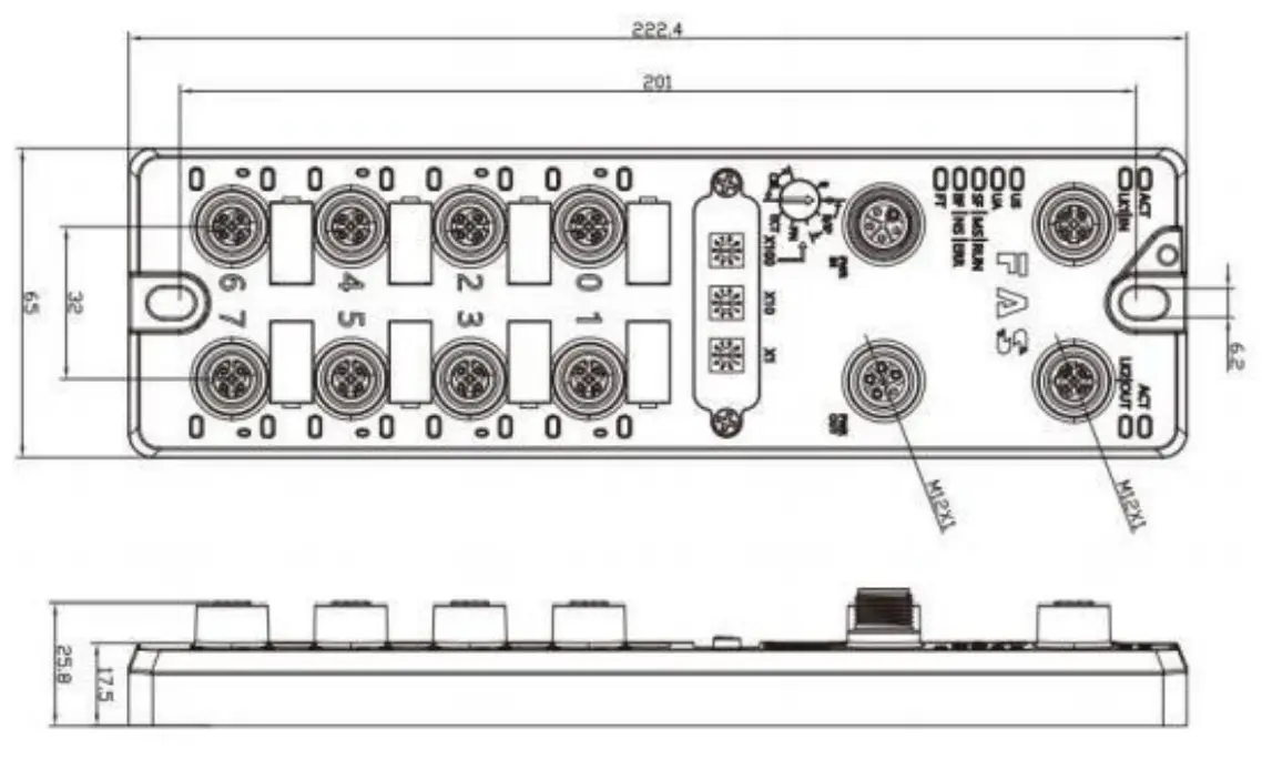
4.1. size
4.2 Mechanical data
| Shell material | Die-cast aluminum case, pearl nickel plated |
| Housing class according to IEC 60529 | IP67 (only in plug-in or plug-in style) |
| Power interface | L-Code (Male and Female) |
| Input port/output port | M12, A-Code (8*female) |
| Size(W*H*D) | 65mm*222mm*25.8mm |
| Installation type | 2-Through Hole Mounting |
| Ground Bus Accessories | M4 |
| Weight | About 670g |
4.3. Operating conditions
| Operating temperature | -5°C | ~ | 70°C | |
| Storage temperature | -25°C | ~ | 70°C | |
4.4. Electrical data
| Voltage | 18~30V DC,Symbol EN61131-2 |
| Voltage fluctuation | <1% |
| Input current at supply voltage 24V | <130mA |
4.5 Network port
| Port | 2 x 10Base-/100Base-Tx |
| Port connection | M12 ,D-Code |
| IEEE 802.3 Compliant Cable Types | Shielded twisted pair, min. STP CAT 5/STP CAT 5e |
| Ddata transfer rate | 10/100 M bit/s |
| Maximum cable length | 100m |
| Flow control | Half condition/full condition(IEEE 802.3- PAUSE) |
4.6 Function indicator

| PT | Green | EtherNet/IP communication protocol |
| Yellow | ProfiNet communication protocol | |
| Blue | EtherCat communication protocol | |
| White | CC-Link IEField basic communication protocol |
ECT Communication Protocol Module Status
| LED | State | Function |
| US | Green | Power is OK |
| Red | Greater than 30V or less than 11V | |
| Flashing red | less than 18V | |
| UA | Green | Power is OK |
| Red | Greater than 30V or less than 11V | |
| Flashing red | less than 18V | |
| SF/MS/RU N | Closure | No error, device initialization |
| Green light flashing | Pre-operational: The device is in a pre-operational state | |
| 2.5Hz | Safe Operation: The device is in safe operation | |
| Green light flashes 1HZ | Running: The device is running | |
| BF/NS/ERR | Steady green | No errors, device EtherCAT communication is working |
| Closure | Invalid configuration | |
| Red light flashes 2.5HZ | local error | |
| Red light flashes 1HZ | Application watch timeout |
EIP Communication Protocol Module Status
| LED | Show | Function |
|
SF/MS/RU N | Green light is always on | Working status: The device is running normally |
| Green light flashes 1HZ | Standby: Device not configured | |
| Green, red and green flashing alternately | Self-test: The device is undergoing a power-on test. | |
| Flashing red 1HZ | Recoverable failures: | |
| Steady red light | Unrecoverable failure | |
| Closure | US no input voltage | |
|
BF/NS/ER R | Green light is always on | Connected |
| Green light flashes 1HZ | Not connected: | |
| Green and red off flashing alternately | Self-test: The device is undergoing a power-on test. | |
| Red light flashes 1HZ | Connection timed out | |
| Steady red light | IP Duplicate: | |
| Closure | US No input voltage or no IP address | |
| US | Green | Input voltage is normal |
| Flashing red | Low input voltage (< 18 V) | |
| UA | Green | The output voltage is normal |
| Flashing red | Low output voltage (< 18 V) | |
| Red always on | No output voltage present (< 11 V) |
PN Communication Protocol Module Status
| LED | Show | Function |
|
SF/MS/RU N | Closure | Works fine |
| Red flashing 3s 1HZ | Bus start | |
| Red always on | System error | |
|
BF/NS/E RR | Closure | Works fine |
| Flashing red 2HZ | No data exchange | |
| Red always on | No configuration; or slow physical link; or no physical link | |
| US | Green | Input voltage is normal |
| Flashing red | Low input voltage (< 18 V) | |
| UA | Green | The output voltage is normal |
| Flashing red | Low output voltage (< 18 V) | |
| Red always on | No output voltage present (< 11 V) |
CIE Communication Protocol Module Status
| LED | Show | Function |
|
SF/MS/RUN | Green light off | Module not connected |
| Green light flashing 2.5HZ | Module not communicating | |
| Green light flashes 1HZ | Module is not configured | |
| Steady green | Running: The device is running | |
| BF/NS/ERR | Closure | Module works fine |
| Steady red light | Communication error | |
| US | Green | Input voltage is normal |
| Flashing red | Low input voltage (< 18 V) | |
| UA | Green | The output voltage is normal |
| Flashing red | Low output voltage (< 18 V) | |
| Red always on | No output voltage present (< 11 V) |

I/O port status
| LED | State | Function |
| 1 | Closure | The status of Pin4 input or output is 0 |
| 1 | Yellow | The status of Pin4 input or output is 1 |
| 1 | Red | Port configured as input: short between Pin1 and 3 |
| 1 | Flashing red | Port configured as output: Pin4 overcurrent |
| 2 | Closure | Port configured as output: short circuit between Pin1 and 3 |
| 2 | Yellow | The status of Pin2 input or output is 0 |
| 2 | Red | The state of Pin2 input or output is 1 |
| 2 | Flashing red | Port configured as input: short between Pin1 and 3 |

Network port status
| LED | State | Function |
| ACT | Closure | Bus rate: 10Mbit/s |
| Yellow | Bus rate: 100Mbit/s | |
| LK1 IN (ECT IN) | Flashing green | Data transmission |
| LK2 IN (ECT OUT) | Flashing green | Data transmission |
Module configuration
5.1.1 Factory reset and communication protocol switching

5.1.2 Network segment modification

5.2 Data mapping
| EIP PN ECT Communication protocol—process output data | |||||||||
| Bytes | Function | 位( Bit) | |||||||
| 7 | 6 | 5 | 4 | 3 | 2 | 1 | 0 | ||
| 0 | PIN4 output | Port7 | Port6 | Port5 | Port4 | Port3 | Port2 | Port1 | Port0 |
| 1 | PIN2 output | Port7 | Port6 | Port5 | Port4 | Port3 | Port2 | Port1 | Port0 |
| Da t a de s c r i p t i o n ( b i n a r y ) : 0 = o f f 1 = o n | |||||||||
| EIP PN ECT Communication protocol—process input data | |||||||||
| Bytes | Function | 位( Bit) | |||||||
| 7 | 6 | 5 | 4 | 3 | 2 | 1 | 0 | ||
| 0 | PIN4 Enter | Port7 | Port6 | Port5 | Port4 | Port3 | Port2 | Port1 | Port0 |
| 1 | PIN2 Enter | Port7 | Port6 | Port5 | Port4 | Port3 | Port2 | Port1 | Port0 |
| 2 | PIN4 short circuit | Port7 | Port6 | Port5 | Port4 | Port3 | Port2 | Port1 | Port0 |
| 3 | PIN2 short circuit | Port7 | Port6 | Port5 | Port4 | Port3 | Port2 | Port1 | Port0 |
| 4 | Port power short circuit | Port7 | Port6 | Port5 | Port4 | Port3 | Port2 | Port1 | Port0 |
| 5 | Module status | Us over volt age | Ua over volt age | overhe at | Us underv oltage | Ua underv oltage | |||
| D a t a d e s c r i p t i o n ( b i n a r y ) : 0 = n o s i g n a l 1 = s i g n a l | |||||||||
| EIP Communication Protocol—Port Configuration | |||||||||
| Bytes | Function | 位( Bit) | |||||||
| 7 | 6 | 5 | 4 | 3 | 2 | 1 | 0 | ||
| 0 | PIN4 model | Port3 | Port2 | Port1 | Port0 | ||||
| 1 | PIN4 model | Port7 | Port6 | Port5 | Port4 | ||||
| 2 | PIN2 model | Port3 | Port2 | Port1 | Port0 | ||||
| 3 | PIN2 model | Port7 | Port6 | Port5 | Port4 | ||||
| Data description (binary): 00 = normally open input 01 = normally closed input 10 = output 11 = input and output adaptive | |||||||||
| EIP Communication Protocol—Port Configuration | |||||||||
| 4 | PIN4 Security Mode | Port3 | Port2 | Port1 | Port0 | ||||
| 5 | PIN4 Security Mode | Port7 | Port6 | Port5 | Port4 | ||||
| 6 | PIN2 Security Mode | Port3 | Port2 | Port1 | Port0 | ||||
| 7 | PIN2 Security Mode | Port7 | Port6 | Port5 | Port4 | ||||
| (On network outage) Safe Mode Configuration: 00 = Hold at 0 01 = Hold at 1 10 = Hold at last value | |||||||||
| CIE communication protocol—process output data | |||||||||
| Bytes | Function | 位( Bit) | |||||||
| 7 | 6 | 5 | 4 | 3 | 2 | 1 | 0 | ||
| 0 | PIN4 output | Port7 | Port6 | Port5 | Port4 | Port3 | Port2 | Port1 | Port0 |
| 1 | PIN2 output | Port7 | Port6 | Port5 | Port4 | Port3 | Port2 | Port1 | Port0 |
| Da t a de s c r i p t i o n ( b i n a r y ) : 0 = o f f 1 = o n | |||||||||
| CIE communication protocol—process input data | |||||||||
| Bytes | Function | 位( Bit) | |||||||
| 7 | 6 | 5 | 4 | 3 | 2 | 1 | 0 | ||
| 0 | PIN4 input | Port7 | Port6 | Port5 | Port4 | Port3 | Port2 | Port1 | Port0 |
| 1 | PIN2 input | Port7 | Port6 | Port5 | Port4 | Port3 | Port2 | Port1 | Port0 |
| 2 | PIN4 short circuit status | Port7 | Port6 | Port5 | Port4 | Port3 | Port2 | Port1 | Port0 |
| 3 | PIN2 short circuit status | Port7 | Port6 | Port5 | Port4 | Port3 | Port2 | Port1 | Port0 |
| 4 | Port power short circuit | Port7 | Port6 | Port5 | Port4 | Port3 | Port2 | Port1 | Port0 |
| 5 | Module status | Us over volt age | Ua over volt age | overhe at | Us underv oltage | Ua underv oltage | |||
| D a t a d e s c r i p t i o n ( b i n a r y ) : 0 = n o s i g n a l 1 = s i g n a l | |||||||||
| *When the CIE ECT communication protocol is used, the PIN input and output mode does not need to be configured for self-adaptation | |||||||||
5.3 PLC Integration Tutorial
(The module communication protocol should be set before configuring the module, see 5.1.1 for details)
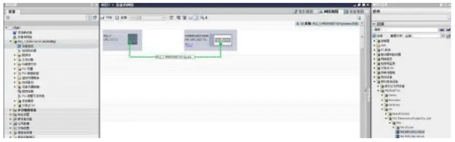
5.3.1 Siemens S7-1200 Portal Integration (PN)
- Install the GSD file

- InPLC—DeviceConfiguration—NetworkView—HardwareCatalog,selectthe moduleanddragitin,click” Unassigned”,andselectthePLCtobeconnected;

- Double-clickthemoduletoentertheconfiguration,
(1)Slotfunctionconfiguration:Selecttherequireddatainthehardware catalog–moduleanddragitinto theslotinthedeviceoverviewwindow;
(2)Moduleportfunctionconfiguration:clickthemoduleicon,select “General”,andthenclickslot1toconfiguretheportfunction
(3) Module function configuration: Click the module icon, select “General”, and then click slot 0 to configure the module function (4)Aftertheconfigurationiscomplete,intheconfigurationview,clickDownload.
 - AssignmodulePNname:PLCswitchtoonlinestate,select”ungroupeddevice”—clickonthe modulename—selectonlineanddi agn osis—function—assignPROFINETdevicename—-Select themoduletobeassignedinthelist(shouldbeselectedaccordingtothephysicalMAC)— Click”AssignName”tocompletetheconfiguration!.

- 3.2OMRONNX1P2SysmacStudioIntegrated(EIP)
1.InstalltheEDSfile:Tools—ETHERNET/IPConnectionSettings—Double-clickPLCinthe window—right-clickontheblankspaceofth etoolboxontherightandselect”ShowEDS
Library”,click”Install”inthepop-upwindow,andselectEDSfileinstallation 2.Createamodule:Click”+”inthetoolboxwindow,fillinthemoduleIPaddress,model name,version,andclick”Add”belowtoco mpletethemodulecreation;
3.Configurationmodule:right-clickthemodule-select”Edit”-configurethecorresponding valuesintheparametersaccordingtoa ctualneedsandclickOKaftercompletion 4.Reateavariableassociation:
(1)Programming–Data–Globalvariablescreatetwoarrays,output2bytes,input6bytes,and thecorrespondinginputandoutputsh ouldbeconfiguredinthenetworkdisclosure; (2)Inthebuilt-inETHERNET/IPportsettingwindow–selectthefirsticon(tab)onthe left–click”RegisterAll”
 (3)Inthebuilt-inETHERNET/IPportsettingwindow–selectthesecondiconontheleft (connection)–click”+”,thetargetdeviceselectsthepreviouslyconfiguredmodule,the IOtypeselectsEXCLUSIVEOwner,andthecorrespondinginputOutput,thetargetvariable mustbefilledwith101,100;thenselectthecorrespondingstartingvariable,andgoonline aftercompletion.Select”TransfertoContro ller”andtheconfigurationiscomplete!
 5.3.3OMRONNX1P2SysmacStudioIntegrated(ECT)
1.InstalltheESIfile:double-clickEtherCATintheconfigurationandsettings–right-clickthemasterdevice–select”ShowESIlibrary”,a ndselecttheESIfileinthepop-upwindowtoinstall 2.ConfigurethemoduletotheEtherCATnetwork:findtheFieldBusModulesinthe toolboxontheright,findthemodulemodeliconanddouble-clicktoaddittothe network
 3. The PLC goes to online mode, right-click the master device, and write the node address of the slave device
4. Variable mapping: Select the configured node in the I/O mapping, fill in the name of the variable, and the configuration is complete! . 5.3.4MitsubishiFX5UWork2Integrated(CIE)
1.InstalltheCCSPfile:firstopenGXWORKS3-Tools-Configurationfilemanagement-Login-CSPPfile(theprojectmustbecl osedtoimportthefile)
2. Click on the left side Project – Parameters – FX5UCPU – Module Parameters – Ethernet Port, Basic Settings – Self Node Settings. Set the own node IP
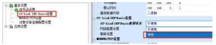
3.ClickCC-LinkIEFBasicsettings-selectwhethertouseCC-LinkIEFBasic-clicktouse 4.ClickCC-LinkIEFBasicsettings-selectnet
workconfigurationsettings-detailed settings;
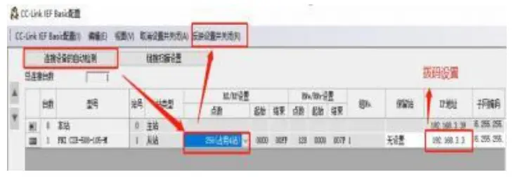
5.Automaticdetectionofconnecteddevices-occupy4stations,theIPaddressissetusing theDIPswitch-reflectthesettingandclose
6.Selectthespecifiedsoftelementforrefreshtarget-softelementnameM-assignsoft elementaddress-application,theconfigur ationiscomplete!


 (4)Aftertheconfigurationiscomplete,intheconfigurationview,clickDownload.
 2.Createamodule:Click”+”inthetoolboxwindow,fillinthemoduleIPaddress,model name,version,andclick”Add”belowtoco mpletethemodulecreation;
 4.Reateavariableassociation:
 (2)Inthebuilt-inETHERNET/IPportsettingwindow–selectthefirsticon(tab)onthe left–click”RegisterAll”
 (3)Inthebuilt-inETHERNET/IPportsettingwindow–selectthesecondiconontheleft (connection)–click”+”,thetargetdeviceselectsthepreviouslyconfiguredmodule,the IOtypeselectsEXCLUSIVEOwner,andthecorrespondinginputOutput,thetargetvariable mustbefilledwith101,100;thenselectthecorrespondingstartingvariable,andgoonline aftercompletion.Select”TransfertoContro ller”andtheconfigurationiscomplete!
 5.3.3OMRONNX1P2SysmacStudioIntegrated(ECT)
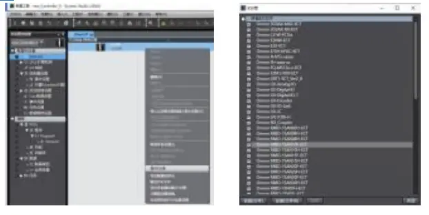 2.ConfigurethemoduletotheEtherCATnetwork:findtheFieldBusModulesinthe toolboxontheright,findthemodulemodeliconanddouble-clicktoaddittothe network
 3. The PLC goes to online mode, right-click the master device, and write the node address of the slave device
 5.3.4MitsubishiFX5UWork2Integrated(CIE)
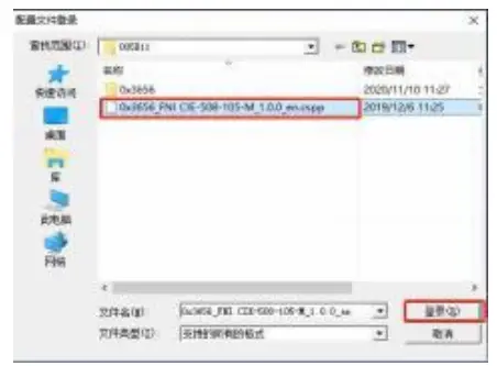


Appendix
6.1.Included materials
FNI MPL contains the following components
·I/O-block
·4blindplugsM12 ·
Groundbus
·ThreadM4x6
·20tags
6.2.Ordercode

6.3OrderingInformation
| Productordercode | Order code |
| FNI MPL-302- 105-M | 007E11 |


