
FAS ELECTRONICS FNI MPL-104-105-M IP 67 Module
Product Information
The FNI MPL-104-105-M IP 67 is a decentralized input and output module that can be connected to an industrial network. It has good chemical and oil resistance characteristics and is suitable for use in aggressive media such as high concentrations of chemicals, oils, lubricants, and coolants with low water content. However, it is important to check the compatibility of these media with the module before use to avoid damage or failure. Unauthorized operation or improper use of the module is not covered by the manufacturer’s warranty.
Product Usage Instructions
Installation and start-up of the FNI MPL-104-105-M IP 67 should only be carried out by trained and specialized personnel who are familiar with the installation and operation of the product andhave the necessary qualifications to do so. To ensure safety and prevent accidents, appropriate safety and accident prevention regulations must be followed by equipment operators. For mechanical connection, refer to section 3.2 of the manual. For electrical connection, refer to section 3.3. To configure the module, refer to section 5.1, and for data mapping, refer to section 5.2. The PLC integration tutorial is provided in section 5.3.
- Manual structure
- This manual is organized by organization, so the chapters are interconnected. Section
- 2:Basic Safety Information.
- Chapter3:Getting Started Guide
- Chapter4:Technical data
- Typography
- The following typographic conventions are used in this manual.
- Enumerate
- The enumerate ionic display data list with bullets.
- Entry 1
- Entry 2
- Action
- Action descriptions are represented by a front triangle.
- The result of the action is represented by an arrow. Action description 1
- Action result
- Action description 2
- Grammar
- Stepprogramscanalsobedisplayednumericallyinparentheses.
- (1) Step 1
- (2) Step 2
- Decimal numbers are displayed without additional indicators (eg 123) Hexadecimal numbers are displayed with an additional indicator hex (eg: 00hex ) or with the prefix “0X” (eg: 0x00)
- Cross-reference
- Cross-references indicate where to find additional information on this topic.
Symbols
Notes
This symbol indicates a general comment.
Notice!
This symbol indicates the most important safety notice.
Acronym
- FNI FAS Network Interface
- I Standard input port
- PN Profinet
- ECT EtherCAT
- CIE CC_link IEF Basic
- EIP Ethernet/IP
- EMC Electromagnetic Compatibility
- FE functional ground
- O Standard output port
Viewing deviations
- The product views and explanations in this manual may deviate from the actual product. They are only left and right solutions
safety
Expected usage
This manual describes as decentralized input and output modules for connection to an industrial network .
Install and start
Precautions!
Installation and start-up may only be carried out by trained and specialized personnel. A qualified individual is one who is familiar with the installation and operation of the product and has the necessary qualifications to do so. Any damage caused by unauthorized operation or illegal and improper use is not covered by the manufacturer’s warranty. Equipment operators are responsible for ensuring that appropriate safety and accident prevention regulations are followed.
General security Notes
Debug and check
Before debugging, you should read the contents of the user manual carefully. The system cannot be used in applications where the safety of personnel depends on the functionality of the equipment. intended use The manufacturer’s warranty coverage and limited liability statement do not cover damage caused by:
- Unauthorized tampering
- Improper use
- Owner/operator’s obligations
This device is an EMC Class A product. This device generates RF noise. The owner/operator must take proper precautions when using this equipment. Use only a power source compatible with this device and connect only approved cables. Fault In the event of a defect or equipment malfunction that cannot be corrected, the equipment must be taken out of operation to avoid possible damage from unauthorized use. Intended use can only be ensured when the enclosure is fully installed.
Corrosion resistance
Precautions!
Modules generally have good chemical and oil resistance characteristics. When used in aggressive media (e.g. high concentrations of chemicals, oils, lubricants and coolants (i.e. very low water content)), these media must be checked before the corresponding application material compatibility confirm. If the module fails or is damaged due to this corrosive medium, no claim for defects can be claimed.- –
Dangerous voltage
Precautions!
Disconnect all power sources before using the equipment!- –
Getting Started Guide
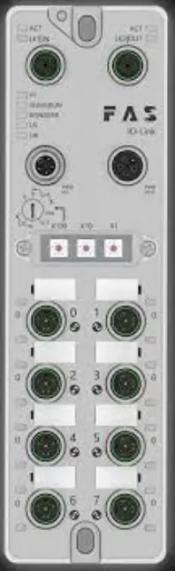
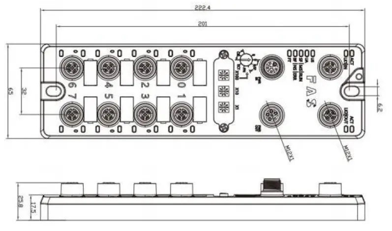
Module overview
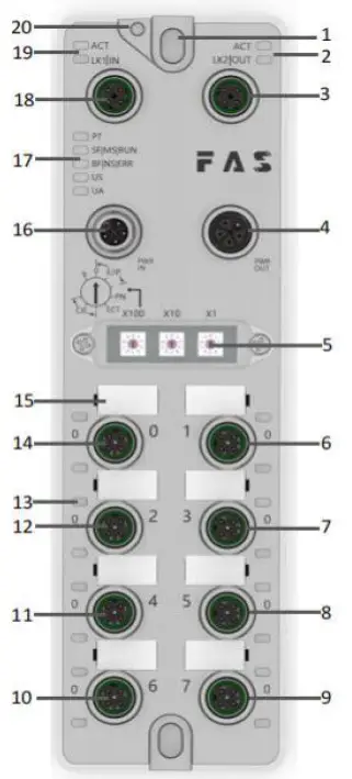
- Mounting Hole
- Network port 2 Status indicator
- Network port 2
- Power outlet
- DIP switch
- Port 1
- Port 3
- Port 5
- Port 7
- Port 6
- Port 4
- Port 2
- Port Status Indicator
- Port 0
- Port Identification Plate
- Power input port
- Module indicator
- Network port 1
- Network port 1 Status indicator
- Ground Connection
Mechanical connection The modules are Connected using 2 M6 bolts and 2 washers. Isolation pads are available as accessories.
Electrical connection
Power interface (L-code)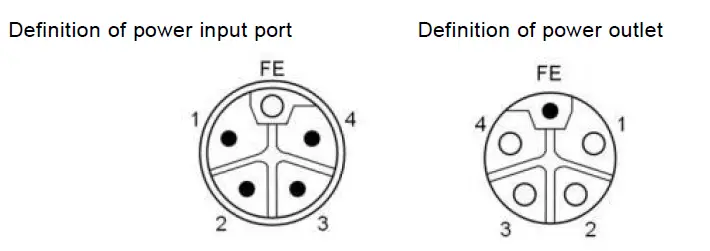
| Pin | Function | Describe |
| 1 | Us+ | +24V |
| 2 | Ua-* | 0V |
| 3 | Us- | 0V |
| 4 | Ua+* | +24V |
| FE | Functional ground* | FE |
Notes:
- If possible, supply sensor/module power and actuator power separately. Total current <9A. The total current of all modules is <9A, even when daisy-chaining the actuator power supply. 2. The FE connection from the housing to the machine must be low impedance and kept as short as possible.
Network Interface (D-code)
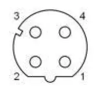
| Pin | Function | |
| 1 | Tx+ | Send data+ |
| 2 | Rx+ | Receive data+ |
| 3 | Tx- | Send data- |
| 4 | Rx- | Receive data- |
Notes:
Unused I/O port sockets must be covered with end caps to meet IP67 rating.
I/O-Port(A-code)
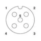
| Pin | Function |
| 1 | 24V |
| 2 | Enter |
| 3 | 0V |
| 4 | Enter |
| 5 | FE |
Note:
- For digital sensor input, please follow the input guidelines of EN61131-2, Type 2.
- The maximum single current of pins 2 and 4 is 2A. The total current of the module is less than 9A.
- Unused I/O port sockets must be covered with end caps to meet IP67 degree of protection.
Technical data
size
Mechanical data
| Shell material | Die-cast aluminum case, pearl nickel plated |
| Housing class according to IEC 60529 | IP67 (only in plug-in or plug-in style) |
| Power interface | L-Code (Male and Female) |
| Input port/output port | M12, A-Code (8*female) |
| Size(W*H*D) | 65mm*222mm*25.8mm |
| Installation type | 2-Through Hole Mounting |
| Ground Bus Accessories | M4 |
| Weight | About 670g |
Operating conditions
| Operating temperature | -5°C | ~ | 70°C | |
| Storage temperature | -25°C | ~ | 70°C | |
Electrical data
| voltage | 18~30V DC,Symbol EN61131-2 |
| voltage fluctuation | <1% |
| Input current at supply voltage 24V | <130mA |
Network port
| Port | 2 x 10Base-/100Base-Tx |
| Port connection | M12 ,D-Code |
| IEEE 802.3 Compliant Cable Types | Shielded twisted pair, min. STP CAT 5/STP CAT 5e |
| Ddata transfer rate | 10/100 M bit/s |
| Maximum cable length | 100m |
| Flow control | Half condition/full condition(IEEE 802.3- PAUSE) |
Function indicator
| PT | Green | EtherNet/IP communication protocol |
| Yellow | ProfiNet communication protocol | |
| Blue | EtherCat communication protocol | |
| White | CC-Link IEField basic communication protocol |
ECT Communication Protocol Module Status
| LED | State | Function |
| US | Green | Power is OK |
| Red | Greater than 30V or less than 11V | |
| Flashing red | less than 18V | |
| UA | Green | Power is OK |
| Red | Greater than 30V or less than 11V | |
| Flashing red | less than 18V | |
| SF/MS/RU N | Closure | No error, device initialization |
| Green light flashing | Pre-operational: The device is in a pre-operational state | |
| 2.5Hz | Safe Operation: The device is in safe operation | |
| Green light flashes 1HZ | Running: The device is running | |
| BF/NS/ER R | Steady green | No errors, device EtherCAT communication is working |
| Closure | Invalid configuration | |
| Red light flashes 2.5HZ | local error | |
| Red light flashes 1HZ | Application watch timeout |
| LED | Show | Function |
|
SF/MS/RU N | Green light is always on | Working status: The device is running normally |
| Green light flashes 1HZ | Standby: Device not configured | |
| Green, red and green flashing alternately | Self-test: The device is undergoing a power-on test. | |
| Flashing red 1HZ | Recoverable failures: | |
| Steady red light | Unrecoverable failure | |
| Closure | US no input voltage | |
|
BF/NS/ER R | Green light is always on | Connected |
| Green light flashes 1HZ | Not connected: | |
| Green and red off flashing alternately | Self-test: The device is undergoing a power-on test. | |
| Red light flashes 1HZ | Connection timed out | |
| Steady red light | IP Duplicate: | |
| Closure | US No input voltage or no IP address | |
| US | Green | Input voltage is normal |
| Flashing red | Low input voltage (< 18 V) | |
| UA | Green | The output voltage is normal |
| Flashing red | Low output voltage (< 18 V) | |
| Red always on | No output voltage present (< 11 V) |
PN communication protocol module status
| LED | Show | Function |
|
SF/MS/RU N | Closure | Works fine |
| Red flashing 3s 1HZ | Bus start | |
| Red always on | System error | |
|
BF/NS/ER R | Closure | Works fine |
| Flashing red 2HZ | No data exchange | |
| Red always on | No configuration; or slow physical link; or no physical link | |
| US | Green | Input voltage is normal |
| Flashing red | Low input voltage (< 18 V) | |
| UA | Green | The output voltage is normal |
| Flashing red | Low output voltage (< 18 V) | |
| Red always on | No output voltage present (< 11 V) |
CIE communication protocol module status
| LED | Show | Function |
|
SF/MS/RU N | Ggreen light off | Module not connected |
| Green light flashing 25HZ | Module not communicating | |
| Green light flashes 1HZ | Module is not configured | |
| Steady green | Running: The device is running | |
| BF/NS/ER R | Closure | Module works fine |
| Steady red light | Communication error | |
| US | Green | Input voltage is normal |
| Flashing red | Low input voltage (< 18 V) | |
| UA | Green | The output voltage is normal |
| Flashing red | Low output voltage (< 18 V) | |
| Red always on | No output voltage present (< 11 V) |
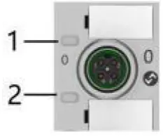
I/O port status
| LED | State | Function |
| 1 | Closure | The state of Pin4 input is 0 |
| 1 | Yellow | The state of Pin4 input is 1 |
| 1 | Red | Short circuit between Pin1 and 3 |
| 2 | Closure | The state of Pin2 input is 0 |
| 2 | Yellow | The state of Pin2 input is 1 |
| 2 | Red | Short circuit between Pin1 and 3 |
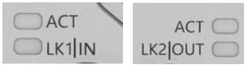
Network port status
| LED | State | Function |
| ACT | Closure | Bus rate: 10Mbit/s |
| Yellow | Bus rate: 100Mbit/s | |
| LK1 IN (ECT IN) | Flashing green | Data transmission |
| LK2 IN (ECT OUT) | Flashing green | Data transmission |
Integrated
Module configuration
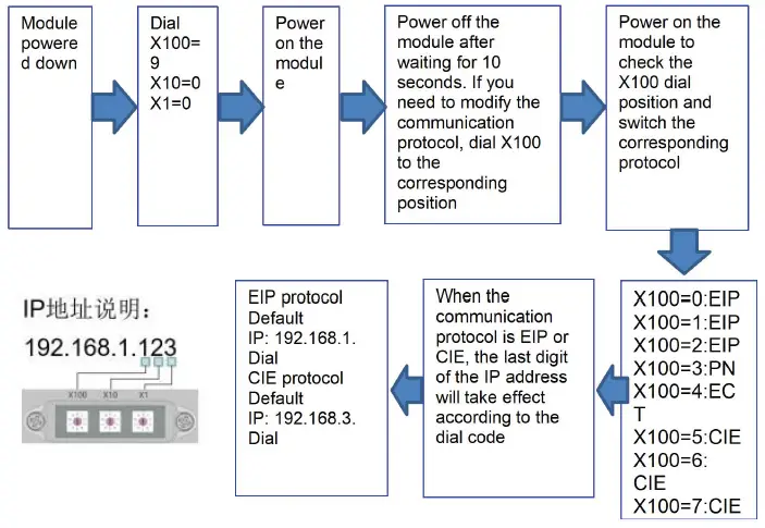
Factory reset and communication protocol switching
Network segment modification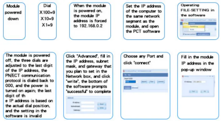
Data mapping
| EIP PN ECT Communication protocol—process output data | |||||||||
| Byte | Function | 位( Bit) | |||||||
| 7 | 6 | 5 | 4 | 3 | 2 | 1 | 0 | ||
| 0 | PIN4 input | Port 7 | Port6 | Port5 | Port4 | Port3 | Port2 | Port1 | Port0 |
| 1 | PIN2 input | Port 7 | Port6 | Port5 | Port4 | Port3 | Port2 | Port1 | Port0 |
| 2 | Port power short circuit | Port 7 | Port6 | Port5 | Port4 | Port3 | Port2 | Port1 | Port0 |
| 3 | Module status | Us overvol tage | Ua overvol tage | Over heat | Us underv oltage | Ua underv oltage | |||
| Da t a de s c r i p t i o n ( b i n a r y ) : 0 = n o s i g n a l 1 = s i g n a l | |||||||||
| EIP Communication Protocol—Port Configuration | |||||||||
| Byte | Function | 位( Bit) | |||||||
| 7 | 6 | 5 | 4 | 3 | 2 | 1 | 0 | ||
| PIN4 port | |||||||||
| 0 | PIN4 mode | Port3 | Port2 | Port1 | Port0 | ||||
| 1 | PIN4 mode | Port7 | Port6 | Port5 | Port4 | ||||
| PIN2 port | |||||||||
| 0 | PIN2 mode | Port3 | Port2 | Port1 | Port0 | ||||
| 1 | PIN2 mode | Port7 | Port6 | Port5 | Port4 | ||||
| Da t a de s c r i p t i o n ( b i n a r y ) : 00 = no r m a l l y op e n in p u t 01 = no r m a l l y c l o s e d in p u t | |||||||||
| CIE Communication protocol—process input data | |||||||||
| Bytes | Function | 位( Bit) | |||||||
| 7 | 6 | 5 | 4 | 3 | 2 | 1 | 0 | ||
| 0 | PIN4 input | Port 7 | Port6 | Port5 | Port4 | Port3 | Port2 | Port1 | Port0 |
| 1 | PIN2 input | Port 7 | Port6 | Port5 | Port4 | Port3 | Port2 | Port1 | Port0 |
| 2 | Port power short circuit | Port 7 | Port6 | Port5 | Port4 | Port3 | Port2 | Port1 | Port0 |
| 3 | module status | Us overvol tage | Ua overvol tage | overh eat | Us underv oltage | Ua underv oltage | |||
| Da t a de s c r i p t i o n ( b i n a r y ) : 0 = n o s i g n a l 1 = s i g n a l | |||||||||
| *When the CIE ECT communication protocol is used, the PIN input and output mode is self-adaptive, and no configuration is required. | |||||||||
PLC Integration Tutorial
(The module communication protocol should be set before configuring the module, see 5.1.1 for details)
Siemens S7-1200 Portal Integration (PN)
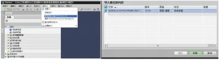
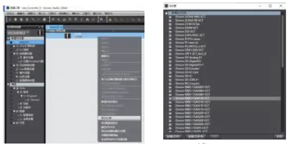
- Install GSD files

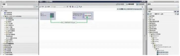
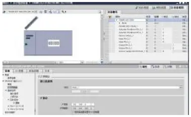
- In PLC—Device Configuration—Network View—Hardware Catalog, select the module and drag it in, click “Unassigned”, and select the PLC to be connected;

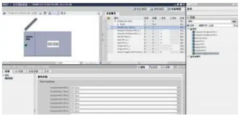
- Double-click the module to enter the configuration,
- Slot function configuration: Select the required data in the hardware catalog–module and drag it into the slot in the device overview window;
- Module port function configuration: click the module icon, select “General”, and then click slot 1 to configure the port function

- Module function configuration: Click the module icon, select “General”, and then click slot 0 to configure the module function

- After the configuration is complete, in the configuration view, click Download.
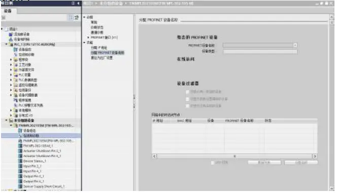
- Assign module PN name: PLC switch to online state, select “ungrouped device”—click on the module name—select online and diagnostics—function—assign PROFINET device name—list Select the module to be assigned (should be selected according to the physical MAC) — Click “Assign Name” to complete the configuration! .

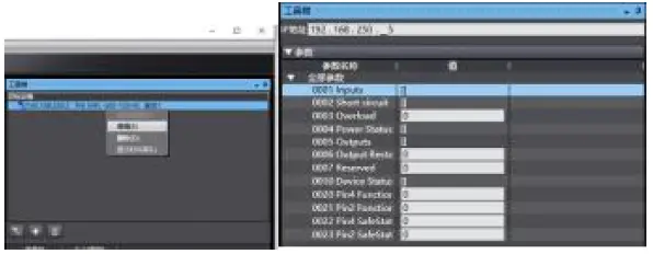
OMRON NX1P2 Integrated in Sysmac Studio (EIP)
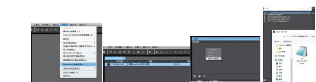
- Install the EDS file: Tools—ETHERNET/IP Connection Settings—Double-click PLC in the window—right-click on the blank space of the toolbox on the right and select “Show EDS Library”, click “Install” in the pop-up window, and select EDS file installation

- Create a module: Click “+” in the toolbox window, fill in the module IP address, model name, version, click “Add” below, and the module is created.;

- Configuration module: Right-click the module–select “Edit”–configure the corresponding values in the parameters according to actual needs, and click OK after completion.


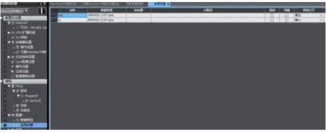
Create a variable association:
- Programming–Data–Global variables Create two arrays, input 4 bytes, and configure the corresponding input and output in the network disclosure;

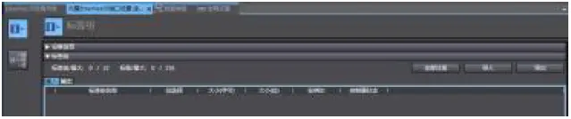
- In the built-in ETHERNET/IP port setting window–select the first icon (tab) on the left–click “Register All”

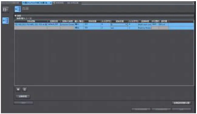
- In the built-in ETHERNET/IP port setting window – select the second icon on the left (connection) – click “+”, the target device selects the previously configured module, the IO type selects EXCLUSIVE Owner, selects the corresponding input and output, the target The variable must be filled with 101,100; then select the corresponding starting variable, and go online after completion. Select “Transfer to Controller” and the configuration is complete!

OMRON NX1P2 Sysmac Studio Integrated (ECT)
- Install the ESI file: double-click EtherCAT in the configuration and settings–right-click the master device–select “Show ESI library”, and select the ESI file in the pop-up window to install

- Configure the module to the EtherCAT network: find the FieldBus Modules in the toolbox on the right, find the module model icon and double-click to add it to the network
- The PLC goes to online mode, right-click the master device, and write the node address of the slave device
- Variable mapping: Select the configured node in the I/O mapping, fill in the name of the variable, and the configuration is complete! .


Mitsubishi FX5U Work2 Integrated (CIE)
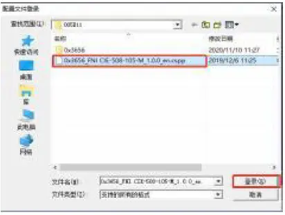
- Install the CCSP file: first open GX WORKS 3-Tools-Configuration file management-Login-CSPP file (the project must be closed to import the file)

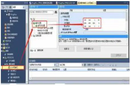
- Click on the left side Project – Parameters – FX5UCPU – Module Parameters – Ethernet Port, Basic Settings – Self Node Settings. Set the own node IP

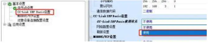
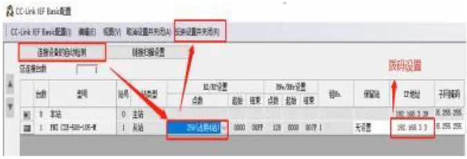
- Click CC-Link IEF Basic Settings – select whether to use CC-Link IEF Basic – click to use

- Click on CC-Link IEF Basic settings – select network configuration settings -detailed settings;

- Auto-detection of connected devices – takes 4 stations, IP address is set with DIP switch – reflects the setting and closes

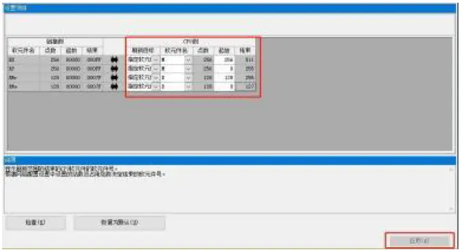
- Refresh target selection specified soft element – soft element name M – assigned soft element address – application, the configuration is complete!


Appendix
ENt Minctarleans eterialSwing composed MPL contains the following components
- 4 blind plugs M12
- Ground bus
- Thread M4×6
- 20 tags
Order code
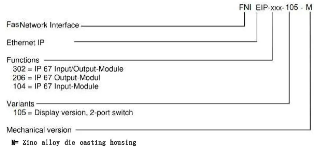
Ordering Information
| Product order code | order code |
| FNI MPL- 104- 105-M | 007C11 |


