
BFt MAXIMA ULTRA 36 Barrier Kit

GENERAL
The automatic electro mechanic barrier was designed to manage openings whose maximum width is 6 meters. It is the ideal solution for vehicle management.
TECHNICAL SPECIFICATIONS
- Power :230Vac/115Vac ±10% 50/60 Hz
- Motor :230Vac 910RPM 0.25 kW
- Absorbed power:370 W
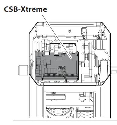
- Control unit :CSB Xtreme
- Safety to impact: Encoder
- Opening time :0.7 ÷ 3.9 s
- Bar length;2 ÷ 6 m
- Operating temp:-40 +60°C
- Actuations over 24h : 20.000 bar length up to 3 m 5.000 bar length up to 6 m
- Protection class : IP 55
- Net weight:69 kg
- Gross weight:72 kg
- Sound pressure level at 1 mt;LpA≤70 dB (A)
- The opening times are evaluated starting from bar in closed position at the beginning of the slowdown, at ambient temperature With built-in heater ON
DIMENSIONS
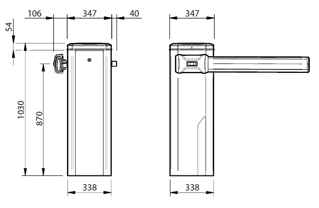
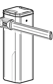
RIGHT barrier
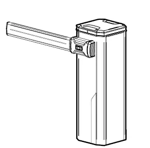
LEFT barrier
WIRING DIAGRAM
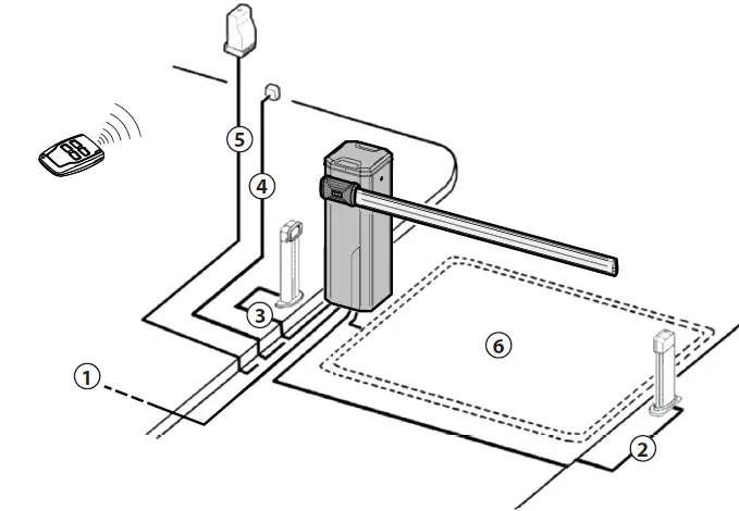
| 1 | Single-phase line | 2+T 1,5mm2 |
| 2 | Transmitter photocell | 2 x 0,5 mm2 |
| 3 | Receiver photocell | 4 x 0,5 mm2 |
| 4 | Key selector | 3 x 0,5 mm2 |
| 5 | Receiver | 4 x 0,5 mm2 |
| Antenna | RG58 | |
| 6 | Magnetic detector |
SECURING THE STRUCTURE
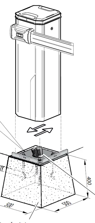
Cement not supplied
Arrange in the foundation corrugated tubes for power supply and system cables (not supplied)
Cramps
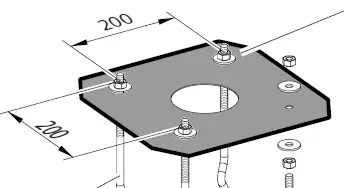 Check the direction of travel indicated on the template, for precise overlapping of the rounded corners of the barrier body.
 It is recommended to remove the template before securing the barrier.
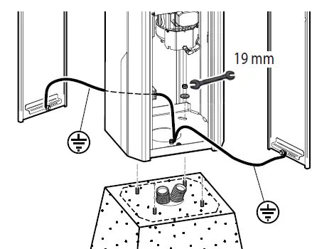
ELECTRICAL CONNECTIONS
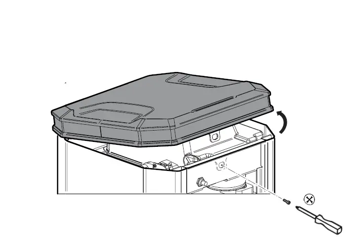
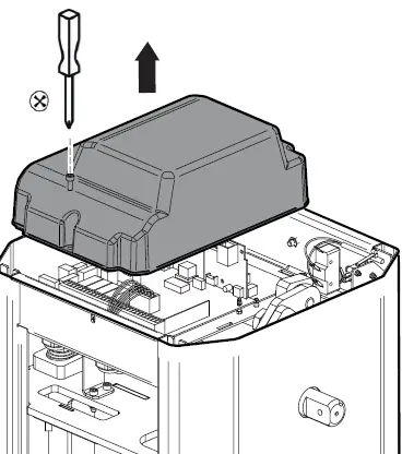
OPEN THE COVER AND ACCESS INSIDE
 THE BARRIER TO REMOVE OF THE DOORS
REMOVE THE COVER OF THE INTERNAL CONTROL UNI
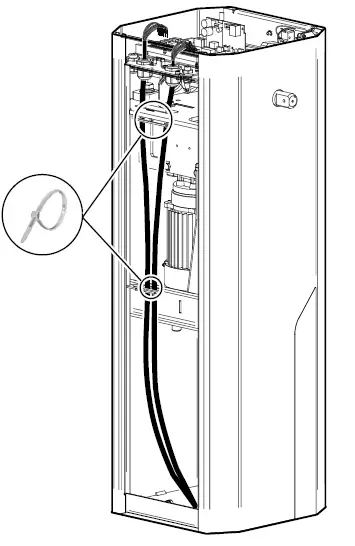
ECURE WITH CABLE TIES
THE USE AND INSTALLATION OF THE CONTROL UNIT.
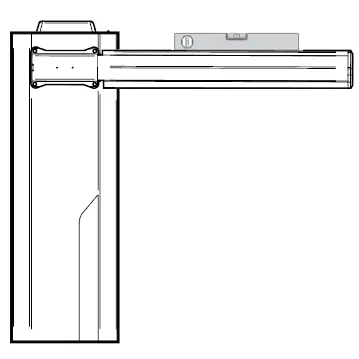
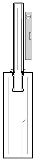
BAR INSTALLATION
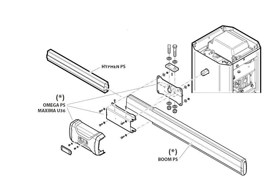
Installation is mandatory in XL configuration supplied. For STD version, it is optional not supplied.
BAR ALIGNMENT
Electrically connect the control unit.
Use the Start command to bring the bar in horizontal position. TO ALIGN THE BAR WITH THE ROAD PAVING, OPERATE THE ADJUSTABLE BAR HOLDER.
Adjustable bar holder
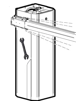
Check that the bar is in horizontal position
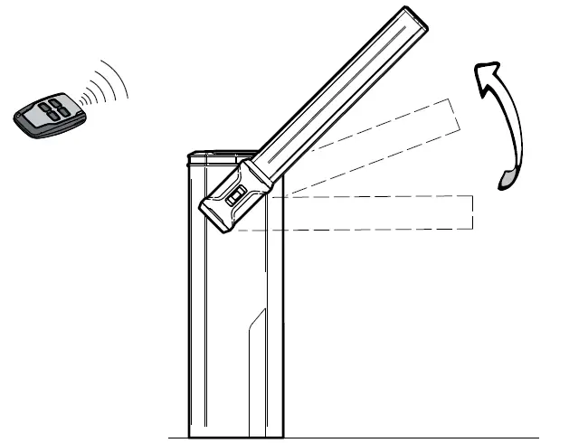
Use the START command to bring the bar to vertical position
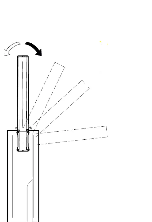
Opening microswitch cam
 Adjust the bar vertically operating the cam of the opening limit switch
Check that the bar is in vertical position.
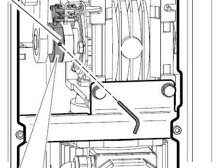
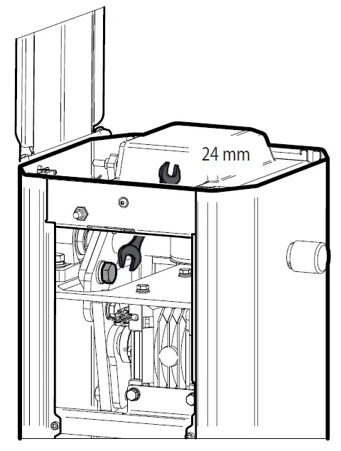
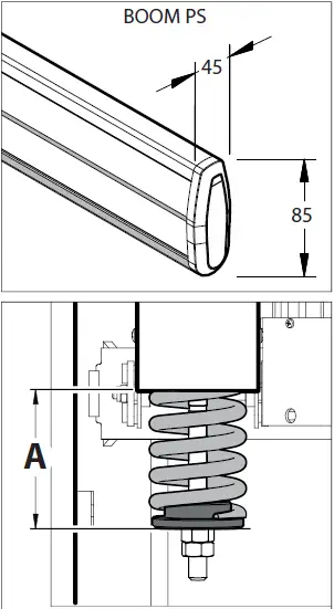
BALANCING THE ARM
BEFORE PERFORMING ANY TASK ON THE EQUIPMENT, CUT OFF THE POWER SUPPLY. DO IT ONLY WITH THE BAR MOUNTED AND POSITIONED VERTICALLY. Remove the screw which secures the lever.
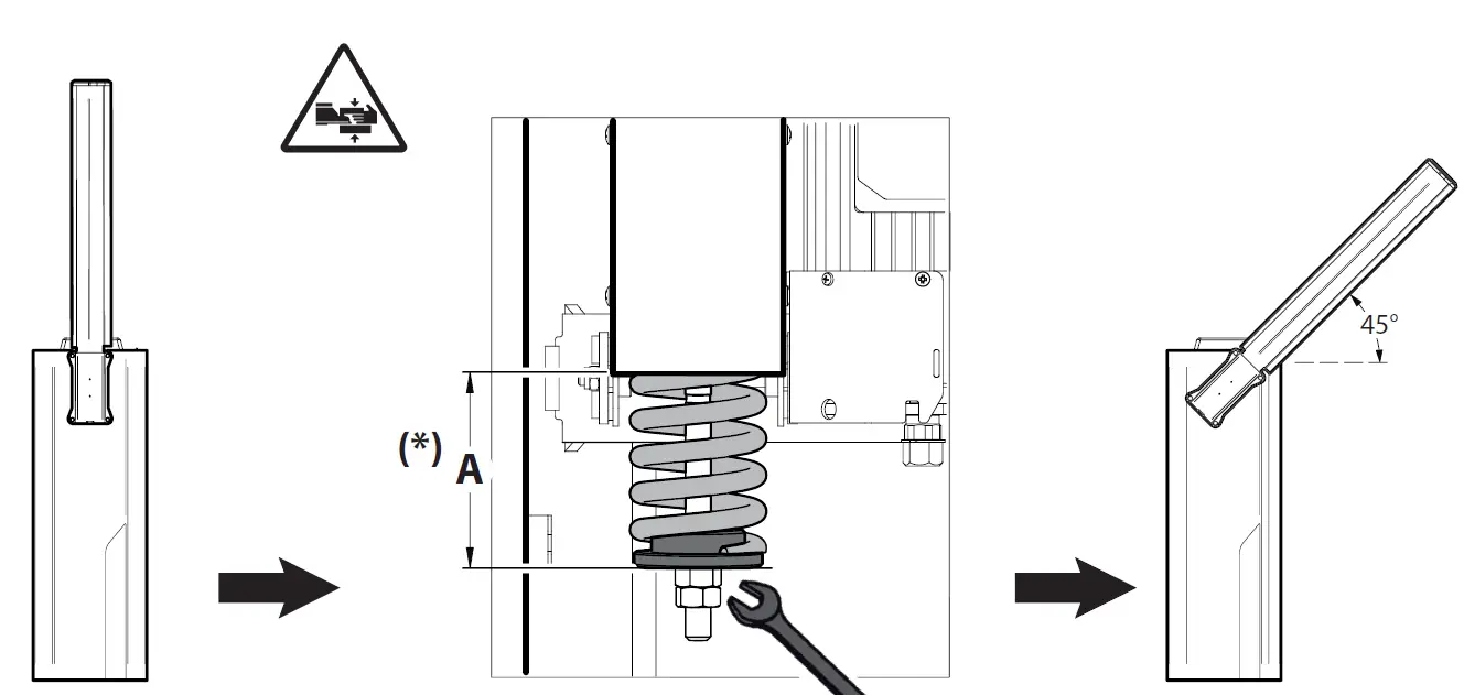
Bring the bar to vertical position. Check that the bar is balanced at approximately 45° position. If necessary, adjust again the distance A.
SPRINGS CALIBRATION APPROXIMATE DATA
 Do not weigh the arm down by applying other accessories.
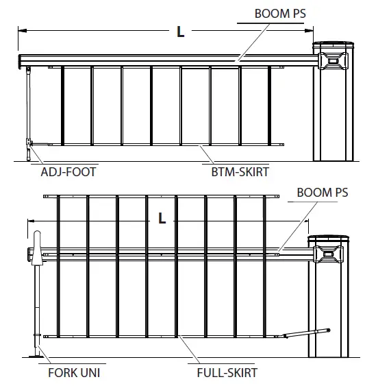
Spring coupling holes (POSITION)
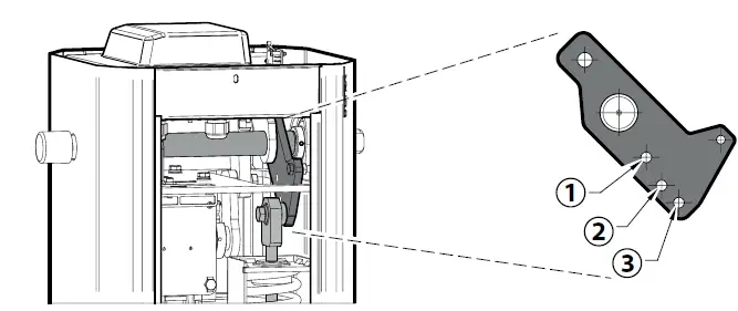
Mandatory installation FORK-UNI
STANDARD version: mandatory the installation of the bar reinforcement HYPHEN PS not included.
| L | 2000 | 2500 | 3000 | 3500 | 4000 | 4500 | 5000 | 5500 | 6000 | |
| BOOM PS | POSITION | 1 | 1 | 1 | 1 | 2 | 2 | 2 | 3 (1) | 3 (1) |
| A (mm) | 130 | 125 | 110 | 90 | 125 | 115 | 100 | 120 | 105 | |
| BOOM PS + ADJ-FOOT | POSITION | 3 | 3 | 2 (3) | ||||||
| A (mm) | 125 | 110 | 95 | |||||||
| BOOM PS + EBB KIT | POSITION | 1 (1) | 2 (1) | 2 (1) | 2 (1) | 3 (1) | 3 (1-2) | 2 (1-3) | ||
| A (mm) | 90 | 125 | 110 | 95 | 125 | 110 | 95 | |||
| BOOM PS + BTM-SKIRT | POSITION | 1 | 2 | 2 (1) | 3 (1) | 3 (1-2) | 3 (1-3) | 3 (1-3) | ||
| A (mm) | 90 | 120 | 105 | 125 | 110 | 125 | 115 | |||
| BOOM PS + BTM-SKIRT + ADJ-FOOT | POSITION | 3 | 3 | 3 (2) | 3 (3) | 3 (3) | ||||
| A (mm) | 125 | 110 | 95 | 120 | 105 | |||||
| BOOM PS + BTM-SKIRT + EBB KIT | POSITION | 3 (1) | 3 (1) | 3 (1-2) | 3 (1-3) | 3 (1-3) | ||||
| A (mm) | 125 | 110 | 95 | 120 | 105 | |||||
| BOOM PS + FULL-SKIRT | POSITION | 1 | 2 | 2 | 2 (1) | 3 (1) | 3 (1-2) | 3 (1-3) | 3 (1-3) | |
| A (mm) | 105 | 125 | 110 | 95 | 115 | 95 | 120 | 105 | ||
| BOOM PS + FULL-SKIRT + EBB KIT | POSITION | 3 (1) | 3 (1) | 3 (1-3 | ||||||
| A (mm) | 115 | 100 | 120 |
START UP, MISE EN SERVI
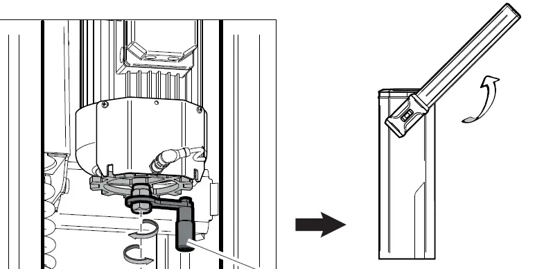
HAND MANOEUVRE
BEFORE PERFORMING ANY TASK ON THE EQUIPMENT, CUT OFF THE POWER SUPPLY. DO IT ONLY WITH THE BAR MOUNTED AND POSITIONED VERTICALLY.
RELEASE CRANK
MAINTENANCE LOG
Installation data
| Installer | |||
| Cliente | |||
| Customer | |||
| Serial number | |||
| Installation date | |||
| Activation date | |||
| Location | |||
Maintenance date
| Nr | Date | Intervention description | Signature | ||
| 1 | Technician | ||||
| Customer | |||||
| 2 | Technician | ||||
| Customer | |||||
| 3 | •Technician | ||||
| Customer | |||||
| 4 | technician | ||||
| Customer | |||||
| 5 | •Technician | ||||
| Customer | |||||
| 6 | Technician | ||||
| Customer | |||||
| 7 | Technician | ||||
| Customer | |||||
| 8 | Technician | ||||
| Customer | |||||
Intervention description
| Nr. | Date | Intervention description | Signature | |||
| 9 | ||||||
| Customer | ||||||
| 10 | Technician | |||||
| Customer | ||||||
| 11 | Technician | |||||
| Customer | ||||||
| 12 | Technician | |||||
| Customer | ||||||
| 13 | Technician | |||||
| Customer | ||||||
| 14 | Technician | |||||
| Customer | ||||||
| 15 | Technician | |||||
| Customer | ||||||
| 16 | Technician | |||||
| Customer | ||||||
| 17 | ||||||
| Customer | ||||||
| 18 | Technician | |||||
| Customer | ||||||
| 19 | Technician | |||||
| Customer | ||||||
| 20 | Technician | |||||
| Client | ||||||
| 21 | ||||||
| Client | ||||||


