![]()
24 GHz NB Radar Sensor User Manual
Product Model: NB24G20V0
Abbreviations
1.1 List of Terminology and Acronyms
| BSD | Blind Spot Detection |
| CAN | Controller Area Network |
| DSP | Digital Signal Processor |
| EMC | ElectroMagnetic Compliance (regulatory standards) |
| FM | Frequency Modulation |
| GHz | Giga-Hertz (10^9) |
| HP | Host Processor |
| LCA | Lane Change Assist |
| MMIC | Monolithic Microwave Integrated Circuit |
| MCU | MicroController Unit |
| NB | Narrow Band |
| PCB | Printed Circuit Board |
| RADA | Radio Detection and Ranging |
| RRCTA | Rear Cross-Traffic Alert |
| RF | Radio Frequency (or Microwave) |
Product Overview
2.1 Product Description
The products described here are part of a family of radars offered by Veoneer. They are intended for automotive use, operating in the 24.050 – 24.250GHz band. The radars are integrated into a vehicle to enhance vehicle safety systems. They can be integrated as a standalone sensor or sensors or as part of a more complex system that also may include cameras, lidar, and other types of sensors to provide features like Automatic Cruise Control, Automatic Emergency Break, Free Space Detections, and other Autonomous Driving functions.
2.2 Product Application Examples
The product can be used, but is not limited to the following applications:
- Blind Spot Detection
- Rear Cross Traffic
- Lane change warning
- Rear collision prevention systems
- Automatic lane change systems
- Pedestrian and Bicycle collision prevention
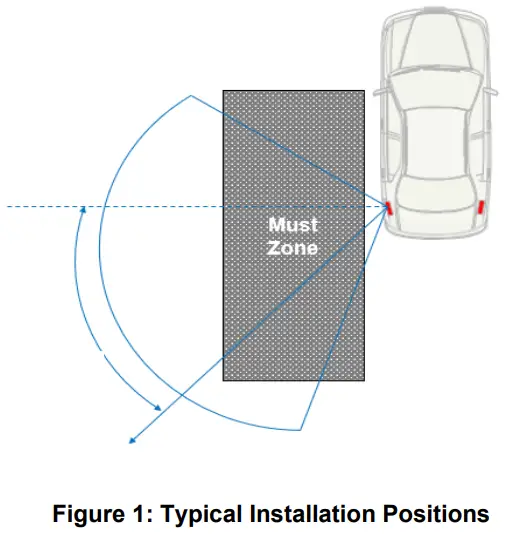
Typical Installation
The radar is typically installed in the positions of the vehicle depicted in Figure 1 often mounted behind a bumper or emblem.
Hardware Description
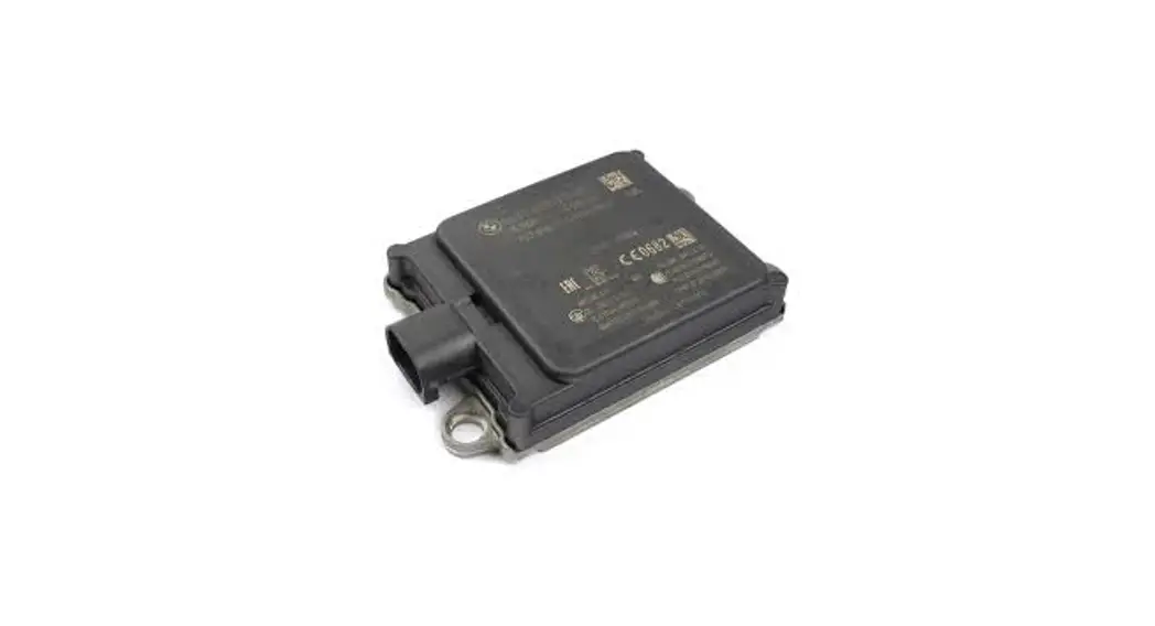
The NB RADAR is a fully integrated 24GHz radar sensor with both RF and DSP modules on the same PCB. The design supports a combination of pulsed Doppler and chirped FM waveforms that can detect moving or stationary vehicles in a high clutter environment. The sensor’s DSP a multicore processor – controls all signal processing, diagnostics, and communications. The RF module generates, transmits, receives, and demodulates radar signals using two Veoneer MMICs. Software algorithms calculate target parameters such as range, speed, and angle, and this information is sent out to the vehicle over the CAN bus.
The components are assembled into a plastic housing that is laser welded together. The sensor has no serviceable parts and can’t be opened without permanent damage.
Sensor Generic Specifications
| Unit | ||
| Sensor Specifications & Functions Operating Conditions | Value | |
| Frequency Band | 24.050 — 24.250 (ISM) | GHz |
| Vehicle Network Interface | CAN 2.0B | – |
| Operating Temperature | -40C to +85 | C (External Ambient) |
| Input Operating Voltage | 8.0-16.0 | VDC |
| RF Output Power (EIRP) | 13. | dBm |
| Operating Life | 15 | yrs. |
| Waveform Parameters | ||
| Cycle Time | 82. | ms |
| Bandwidth | <200 | MHz |
| Physical Parameters | ||
| Size | 72 x 63 x 16 | mm (excluding connector) |
| Weight | <75 | g |
| Vehicle Physical Interface | Standard is 6 Pin DUAL CAN |
Table 1: Sensor Specifications
Sensor Features
The BSD algorithm detects and reports “Objects of Interest” on either side of the vehicle, within a specified “blind spot” zone. The feature generates a signal which is used to drive a visual display placed in the outside view mirror to alert the driver to the presence of objects of interest within the defined SBZA zone.
The LCA algorithm detects and reports to the driver that a vehicle is rapidly approaching the host vehicle in one of the adjacent lanes. The feature generates a signal which is used to drive a visual display placed in the outside view mirror and/or request a chime or vibrating seat cushion, to alert the driver to the approach of objects of interest within the defined LCA zone.
The RCTA algorithm detects and reports “Objects of Interest” behind the host vehicle, within a specified RCTA coverage zone. The feature generates a signal which is used to drive a visual display to alert the driver of the presence of objects of interest that may cause a collision with the host vehicle within the defined RCTA zone.
Conformance Statements
7.1 USA
This device complies with Part 15 of the FCC Rules. Operation is subject to the following two conditions: (1) this device may not cause harmful interference, and (2) this device must accept any interference received, including interference that may cause undesired operation. CAUTION TO USERS Changes or modifications not expressly approved by the party responsible for compliance could void the user`s authority to operate the equipment.
Additionally, it should be mentioned, that the integrator is advised to have this statement in their user manual as well.
CAUTION TO USERS
Changes or modifications not expressly approved by the party responsible for compliance could void the user’s authority to operate the equipment.
7.2 Canada
This device contains license-exempt transmitter(s)/receiver(s) that comply with Innovation, Science, and Economic Development Canada’s license-exempt RSS(s). Operation is subject to the following two conditions: (1) This device may not cause interference. (2) This device must accept any interference, including interference that may cause undesired operation of the device.
7.3 Radio Frequency Exposure Information
This equipment should be operated at a minimum distance of 20 cm from the user. This equipment complies with FCC and IC radiation exposure limits set forth for an uncontrolled environment. This equipment should be installed and operated with a minimum distance of 20 cm between the radiator and your body. This transmitter must not be co-located or operating in conjunction with any other antenna or transmitter.
7.4 Europe
Hereby, Veoneer US, Inc declares that the radio equipment type NB24G20V0 is in compliance with Directive 2014/53/EU.
Operational frequency band: 24.050 24.250GHz
Maximum radio-frequency output power: < 20dBm peak eirp
The full text of the EU declaration of conformity is available at the following internet address: https://www.veoneer.com/en/regulatory
Revision History
The revision number in table below is the PLM revision and version number. The Description/Comment is the same description that is found in PLM in check comment.
| Revision | Date | Author(s) | Description/comment |
| 000 v1 | 2021-01-07 | Harsha Deshpande | Initial release |
| 000 v2 | 2021-04-12 | Harsha Deshpande | Added FCC 15.21 conformance statement |
Table 2: Revision History
Veoneer US, Inc.
26360 American Drive
Southfield, Michigan 48034 USA
Phone: +1 248 223 0600
Fax: +1 248 223 8833


