![]()
Quick Start Reference
S100 (.5~30HP)
Introduction
This quick start reference is meant to be a supplement to the User Manual included in the VFD packaging. This reference informs the installer of the proper steps for mounting, wiring, and basic programming/operation of the S100 VFD up to 22kW/30HP.![]() Improper wiring and operation may result in serious personal injury or death.
Improper wiring and operation may result in serious personal injury or death.
Follow the recommended wiring practices suggested in this document as well as the User Manual. The minimum size of the protective earth (ground) conductor shall comply with local safety regulations and applicable codes.
Please review all S100 related documents included with the product before proceeding with any installation and wiring.
LS Electric America 980 Woodlands Parkway Vernon Hills, IL 60061 800-891-2941
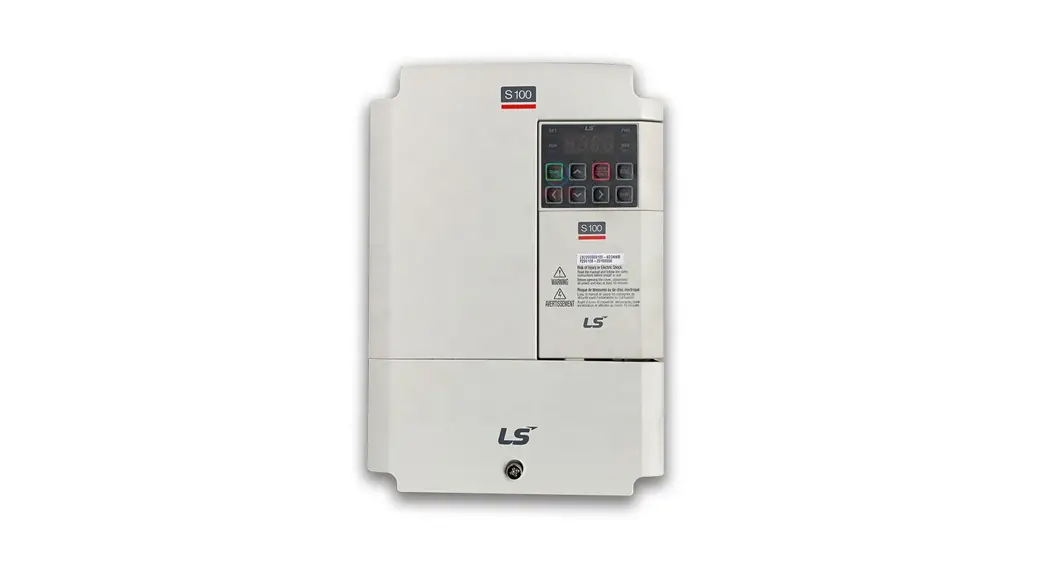
Step 1 S100 Model Number and Mounting
Verify that you have ordered and received the correct VFD by checking the nameplate information. Utilize the example nameplate below to assist you with this.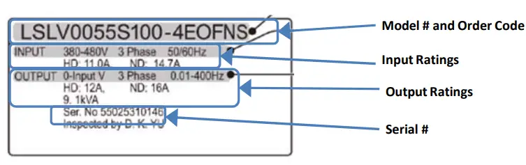 Important!
Verify that the input voltage rating matches the voltage source which will be applied to the VFD.
Confirm that the output power of the VFD is equal to or greater than the rating of the motor which will be connected.
Mounting
In order to maximize the lifespan of your S100 VFD, follow the proper installation and environment recommendations. The User Manual contains further details on the exact dimensions and weights of each capacity S100.
Cover Removal
After mounting, and in order to move onto the wiring step, loosen the captive screw on the terminal cover. Squeeze the tabs and “hinge off” the cover. Squeeze tabs and slide up the wire guide to expose the power terminals. This wire guide can be disposed of if you have purchased a NEMA 1 conduit kit. For the IP66 enclosure, loosen all screws and lift from the bottom.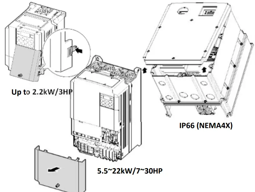
Step 2 Connect Line and Motor
Power Utilize the below wiring diagrams to properly wire the main power connections to the VFD. This step should be done with power OFF! Refer to the User Manual for proper wire gauge recommendations. Be sure to follow good wiring and grounding practices. Follow applicable local codes if needed.![]() Lethal voltages are present. Be sure that all power is turned OFF while performing the recommended power wiring. Reinstall all protective covers on the S100 before reapplying power
Lethal voltages are present. Be sure that all power is turned OFF while performing the recommended power wiring. Reinstall all protective covers on the S100 before reapplying power
Below is the proper wiring for both Single Phase and Three-phase applications. The physical terminal layout will change across the different S100 capacities and enclosure types. Terminal names (e.g. R, S, T, etc) will remain consistent.
Single Phase Input S100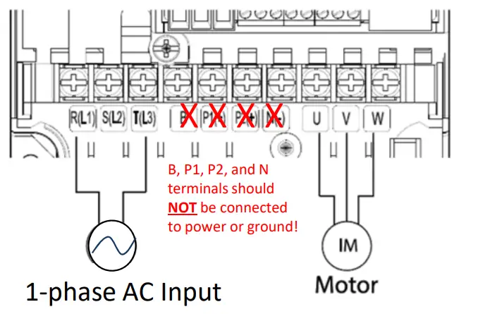
Three Phase Input S100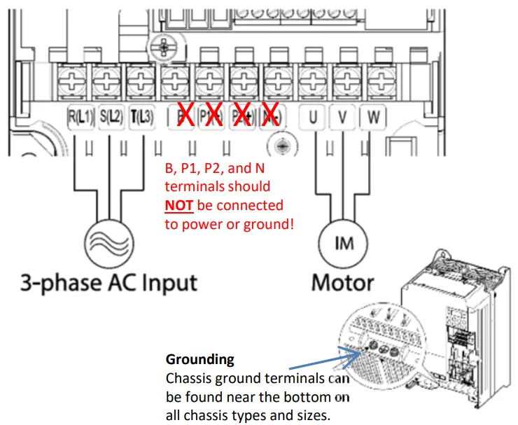 Step 3 Verify Motor Direction
This step explains how to check motor direction by running the motor at a low speed via the keypad. Verify that the power and motor wiring match the previous step and covers are installed before applying power. At first power-up, the display will look like below. “0.00” represents a frequency reference of 0.00 Hz.
Setting Speed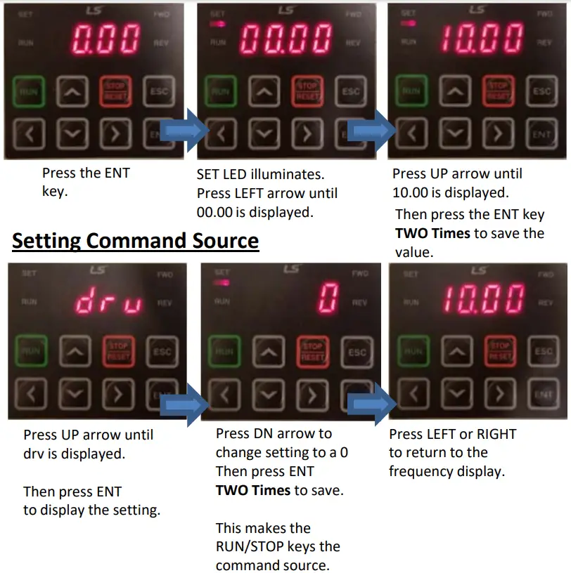
Checking Direction
Check that it is safe to run the motor at low speed.
When ready, press to ![]() the motor. The display will briefly show the output frequency of the VFD until it reaches 10Hz.
the motor. The display will briefly show the output frequency of the VFD until it reaches 10Hz.
Look at the motor shaft to verify rotation is correct. Press the ![]() key to STOP.
key to STOP.
If the motor direction is incorrect, stop the motor with the ![]() key, and power down the VFD.
key, and power down the VFD.![]() Wait at least 5 minutes to let the VFD capacitors discharge.
Wait at least 5 minutes to let the VFD capacitors discharge.
Swap any two output leads between the VFD and the motor. This will change motor direction. Verify correct rotation via the previous steps.
Keypad Navigation and Parameter Changes
Navigate and select different parameters by using the directional arrows on the keypad
From the main screen (0.00), the UP and DN arrows will navigate through the operation group. The drive group contains many basic start-up parameters and monitors. See a partial list of operation group parameters below.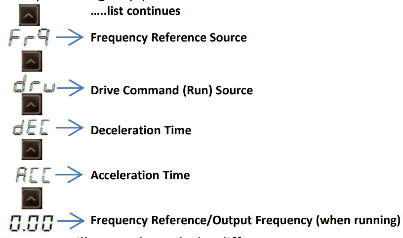 Pressing the LEFT or RIGHT arrows will move through the different parameter groups. While the UP and DN arrows will navigate through the different parameter code #s in the selected group.
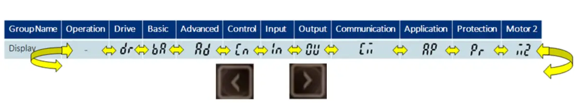
Any of the above parameters and monitors settings can be accessed by pressing the ENT key. Pressing the ENT key again, or the ESC key will go back to the previous display.
Changing Acceleration Time Example
- Press the UP arrow from the main display (0.00) until ACC is displayed.
- Press the ENT key one time to display the current setting.
- Use the UP and DN arrows to increase and decrease the value.
- Use the LEFT or RIGHT arrows to move the cursor over to select different digits.
- Press the ENT key TWO TIMES once the desired value is set. This saves the change.
- ACC will be displayed again indicating the parameter change has taken effect.
Important: Press the ENT key two times to save parameter changes!
Step 5 Control Wiring
This step shows common wiring examples for both the run command and frequency reference.
Run Command Wiring
2-Wire Control 2-wire control consists of maintained run signals. This can be accomplished via toggle switches, relays, jumpers, etc. Default parameters support this operation.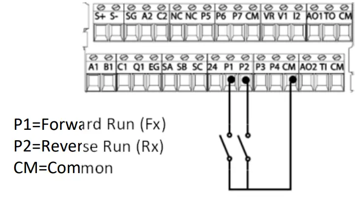 3-Wire Control
3-Wire control consists of momentary push buttons to run and stop the VFD. The Forward and Reverse buttons are Normally Open while the Stop button is Normally Closed. Set parameter In67=14 if using P3 (like below) for the Stop button.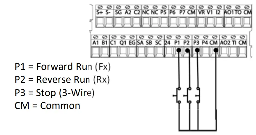
Frequency Reference Wiring
Speed POT Wiring (0-10VDC)
Controlling the VFD with an external speed POT can be accomplished by setting frq=2 and wiring like below. For 0-10VDC signals from a PLC or Controller simply wire to V1 and CM.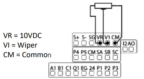 PLC or Controller Wiring (4-20mA)
For speed control over a 4-20mA signal set frq=5.
Important: Verify that SW2 dip switch on the terminal board to `II’ (down) for 4- 20mA signal.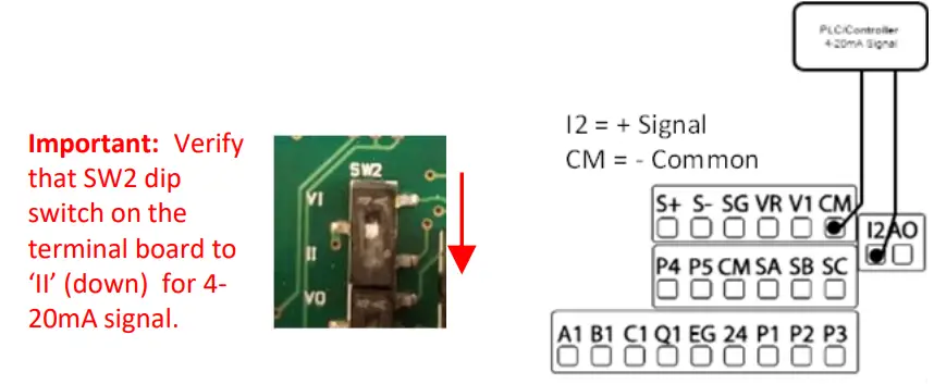
Step 6 Basic Setup Parameters
The basic drive and motor parameters are shown in the below table. Set the parameters according to your specific application.
Required Motor Parameters
Set the below motor parameters based on the motor nameplate.
| Group | No | Description | Default | Set Options |
| dr | 14 | Motor Capacity | Depends on drive | Depends on drive |
| bA | 11 | Poles | 4 | 2 – 12 |
| bA | 13 | Motor Rated Current | Depends on drive | Depends on drive |
| bA | 15 | Motor Voltage | Depends on drive | Depends on drive |
HP to the kW conversion chart
| HP | 1/4 | 1/2 | 1 | 2. | 2 | 3 | 5 | 7 | 10 | 15 | 20 | 25 | 30 | 40 | 50 | 60 | 75 | 100 |
| kW | _ 0.2. 0.4 | 0.75 | 1. | 2. | 2.2_ 3.7_ 5.5 | 7.5_ 11.0_ 15.0 | 18.5_ 22.0 | 30.0 | 37.0 | 45.0_ 55.0 | 75 | |||||||
Motor RPM to Poles chart
| RPM | 3600 | 1800 | 1200 |
| Poles | 2 | 4 | 6 |
Example: If the actual motor RPM is 3450. Set Motor Poles = 2. This is due to a motor slip. In this example, The motor
has 150 RPM of slip. (Slip=Synchronous speed-Rated Speed)
Commonly Set Parameters
| Group | No | Description | Default | Set Options | |
| Operation | 0.00 | Command Freq | 0.00 | 0 – Max Freq | |
| Operation | ACCESS | Access Time | 20 | 0 – 6000 | |
| Operation | dEC | Decel Time | 30 | 1- 6000 | |
| Operation | drV | Run Command | 1 | Fx/Rx-1 | 0: Keypad |
| 1:Fx/Rx-1 | |||||
| 2:Fx/Rx-2 | |||||
| 3:Comm RS485 | |||||
| 4:Field Bus | |||||
| Operation | Frq | Freq Command | 0 | Keypad-1 | 0: Keypad-1 |
| 1:Keypad-2 | |||||
| 2:V1 | |||||
| 4: V2 | |||||
| 5:12 | |||||
| 6: Comm RS485 | |||||
| 8: Field Bus | |||||
| 12: Pulse | |||||
| bA | 19 | Input Voltage | 220/380 | 170 – 480V | |
Optional Parameters
- To automatically start after a power loss, set Ad.10=1.
- Enable phase loss protection by setting the virtual dipswitches in Pr.5 both to the up (top) position.
- Enable auto-restart after a fault trip by setting the below…
- Pr.8= 1
- Pr.9= # of retry attempts
LS Electric America
980 Woodlands Parkway
Vernon Hills, IL 60061
800‐891‐2941
Introduction
This quick start reference is meant to be a supplement to the User Manual included in the VFD packaging. This reference informs the installer of the proper steps for mounting, wiring, and basic programming/operation of the S100 VFD up to 22kW/30HP.![]() Improper wiring and operation may result in serious personal injury or death.
Improper wiring and operation may result in serious personal injury or death.
Follow the recommended wiring practices suggested in this document as well as the User Manual. The minimum size of the protective earth (ground) conductor shall comply with local safety regulations and applicable codes.
Please review all S100 related documents included with the product before proceeding with any installation and wiring.
LS Electric America 980 Woodlands Parkway Vernon Hills, IL 60061 800-891-2941
Step 1 S100 Model Number and Mounting
Verify that you have ordered and received the correct VFD by checking the nameplate information. Utilize the example nameplate below to assist you with this.Important!
Verify that the input voltage rating matches the voltage source which will be applied to the VFD.
Confirm that the output power of the VFD is equal to or greater than the rating of the motor which will be connected.
Mounting
In order to maximize the lifespan of your S100 VFD, follow the proper installation and environment recommendations. The User Manual contains further details on the exact dimensions and weights of each capacity S100.
Cover Removal
After mounting, and in order to move onto the wiring step, loosen the captive screw on the terminal cover. Squeeze the tabs and “hinge off” the cover. Squeeze tabs and slide up the wire guide to expose the power terminals. This wire guide can be disposed of if you have purchased a NEMA 1 conduit kit. For the IP66 enclosure, loosen all screws and lift from the bottom.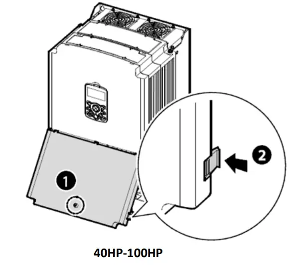
Step 2 Connect Line and Motor
Power Utilize the below wiring diagrams to properly wire the main power connections to the VFD. This step should be done with power OFF! Refer to the User Manual for proper wire gauge recommendations. Be sure to follow good wiring and grounding practices. Follow applicable local codes if needed.![]() Lethal voltages are present. Be sure that all power is turned OFF while performing the recommended power wiring. Reinstall all protective covers on the S100 before reapplying power
Lethal voltages are present. Be sure that all power is turned OFF while performing the recommended power wiring. Reinstall all protective covers on the S100 before reapplying power
Below is the proper wiring for both Single Phase and Three-phase applications. The physical terminal layout will change across the different S100 capacities and enclosure types. Terminal names (e.g. R, S, T, etc) will remain consistent.
Single Phase Input S100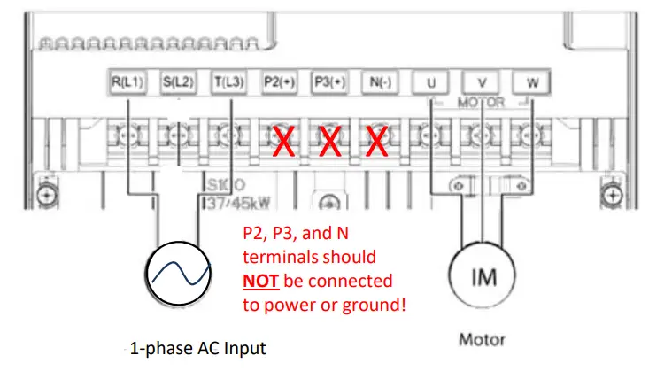 Three-Phase Input S100
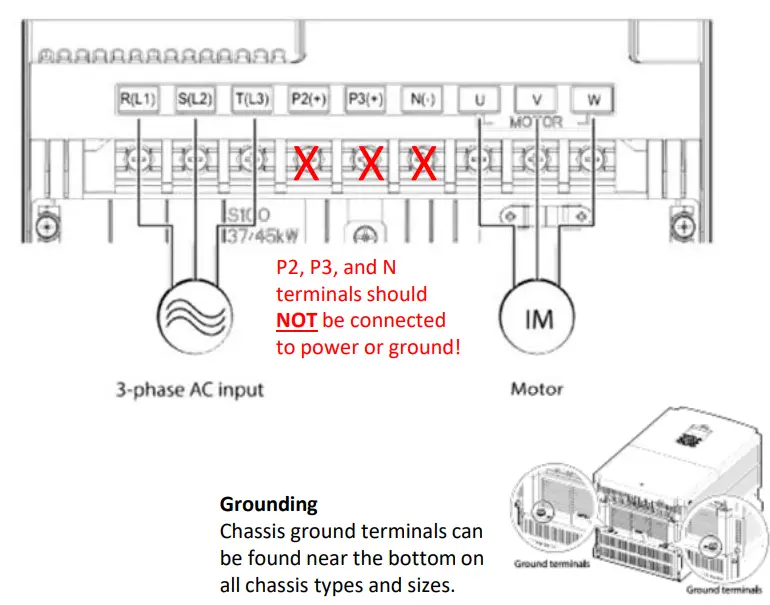
Step 3 – Verify Motor Direction
This step explains how to check motor direction by running the motor at a low speed via the keypad. Verify that the power and motor wiring matches the previous step and covers are installed before applying power.
At first power-up, the display will look like below. “0.0 Hz” represents a default frequency reference..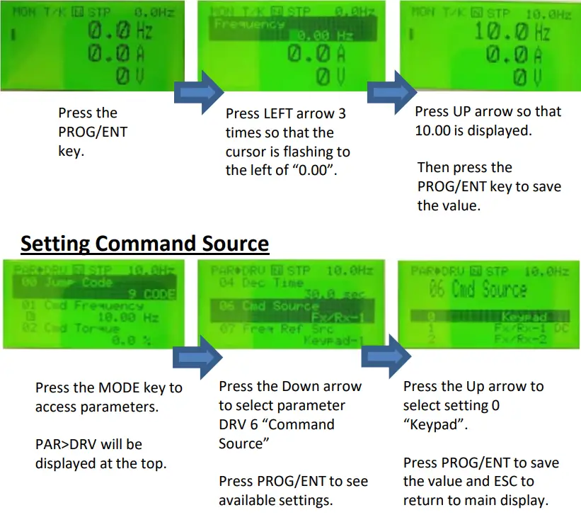
Checking Direction
Check that it is safe to run the motor at low speed. When ready, press ![]() to RUN the motor. The display will briefly show the output frequency of the VFD until it reaches 10Hz. Look at the motor shaft to verify rotation is correct. Press the
to RUN the motor. The display will briefly show the output frequency of the VFD until it reaches 10Hz. Look at the motor shaft to verify rotation is correct. Press the![]() key to STOP.
key to STOP.
If the motor direction is incorrect, stop the motor with the key![]() , and power down the VFD.
, and power down the VFD.![]() Wait at least5 minutes to let the VFD capacitors discharge.
Wait at least5 minutes to let the VFD capacitors discharge.
Swap any two output leads between the VFD and the motor. This will change motor direction. Verify correct rotation via the previous steps.
Keypad Navigation and Parameter Changes
Navigate and select different parameters by using the directional arrows on the keypad while in the PAR Mode ( ![]() ).
).
From the main screen, the MODE key will change the keypad to display the Parameter (PAR) mode. The PAR model contains all parameters and monitors. These parameters and monitors are divided into intuitive groups. Pressing the LEFT or RIGHT arrows will move through the different parameter groups. While the UP and DOWN arrows will navigate through the different parameter codes #s in the selected group.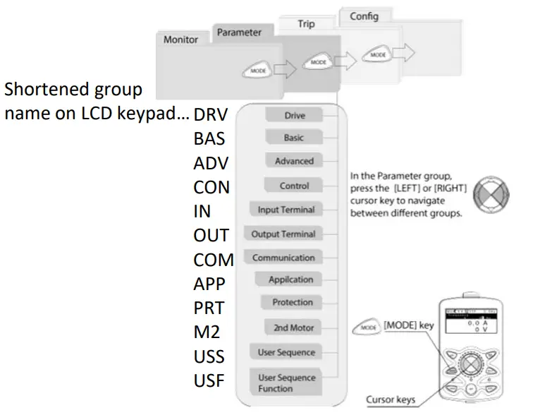
Any of the above parameters settings can be changed by pressing the PROG/ENT key, selecting the new setting with the arrows, and pressing PROG/ENT again to save.
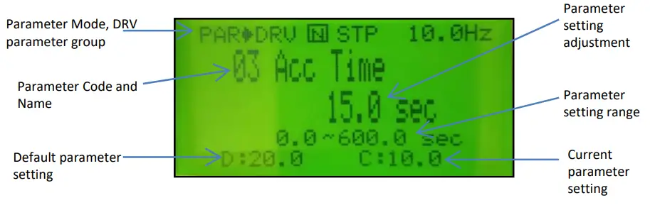
Changing Acceleration Time Example
- Press the MODE key from the main display to access PAR Mode.
- In the DRV group, press down to select DRV 03 (Acc Time).
- Press the PROG/ENT key to access the current setting.
- Use the UP and DOWN arrows to increase and decrease the value.
- Use the LEFT or RIGHT arrows to move the cursor over to select different digits.
- Press the PROG/ENT key once the desired value is set. This saves the change.
- DRV 03 will be displayed again indicating the parameter change has taken effect with the new value displayed.
Step 5 Control Wiring
This step shows common wiring examples for both the run command and frequency reference.
Run Command Wiring
2-Wire Control
2-wire control consists of maintained run signals. This can be accomplished via toggle switches, relays, jumpers, etc. Default parameters support this operation.3-Wire Control
3-Wire control consists of momentary push buttons to run and stop the VFD. The Forward and Reverse buttons are Normally Open while the Stop button is Normally Closed. Set parameter In67=14 if using P3 (like below) for the Stop button.
Frequency Reference Wiring
Speed POT Wiring (0-10VDC)
Controlling the VFD with an external speed POT can be accomplished by setting DRV7=2 V1 and wiring like below. For 0-10VDC signals from a PLC or Controller simply wire to V1 and CM.
PLC or Controller Wiring (4-20mA)
For speed control over a 4-20mA signal set DRV7=5 I2.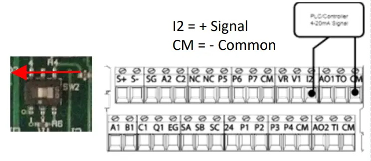
Important: Verify that SW2 dip switch on the terminal board to `I2′ (LEFT) for 4- 20mA signal.
Step 6 Basic Setup Parameters
The basic drive and motor parameters are shown on the below table. Set the parameters according to your specific application.
Required Motor Parameters
Set the below motor parameters based on the motor nameplate.
| Group | No | Description | Default | Set Options |
| dr | 14 | Motor Capacity | Depends on drive | Depends on drive |
| bA | 11 | Poles | 4 | 2 – 12 |
| bA | 13 | Motor Rated Current | Depends on drive | Depends on drive |
| bA | 15 | Motor Voltage | Depends on drive | Depends on drive |
HP to the kW conversion chart
| HP | 1/4 | 1/2 | 1 | 2. | 2 | 3 | 5 | 7 | 10 | 15 | 20 | 25 | 30 | 40 | 50 | 60 | 75 | 100 |
| kW | _ 0.2. 0.4 | 0.75 | 1. | 2. | 2.2_ 3.7_ 5.5 | 7.5_ 11.0_ 15.0 | 18.5_ 22.0 | 30.0 | 37.0 | 45.0_ 55.0 | 75 | |||||||
Motor RPM to Poles chart
| RPM | 3600 | 1800 | 1200 |
| Poles | 2 | 4 | 6 |
Example: If the actual motor RPM is 3450. Set Motor Poles = 2. This is due to a motor slip. In this example, The motor
has 150 RPM of slip. (Slip=Synchronous speed-Rated Speed)
Commonly Set Parameters
| Group | No | Description | Default | Set Options | |
| Operation | 0.00 | Command Freq | 0.00 | 0 – Max Freq | |
| Operation | ACCESS | Access Time | 20 | 0 – 6000 | |
| Operation | dEC | Decel Time | 30 | 1- 6000 | |
| Operation | drV | Run Command | 1 | Fx/Rx-1 | 0: Keypad |
| 1:Fx/Rx-1 | |||||
| 2:Fx/Rx-2 | |||||
| 3:Comm RS485 | |||||
| 4:Field Bus | |||||
| Operation | Frq | Freq Command | 0 | Keypad-1 | 0: Keypad-1 |
| 1:Keypad-2 | |||||
| 2:V1 | |||||
| 4: V2 | |||||
| 5:12 | |||||
| 6: Comm RS485 | |||||
| 8: Field Bus | |||||
| 12: Pulse | |||||
| bA | 19 | Input Voltage | 220/380 | 170 – 480V | |
Optional Parameters
- To automatically start after a power loss, set Ad.10=1.
- Enable phase loss protection by setting the virtual dipswitches in Pr.5 both to the up (top) position.
- Enable auto-restart after a fault trip by setting the below…
- Pr.8= 1
- Pr.9= # of retry attempts
LS Electric America
980 Woodlands Parkway
Vernon Hills, IL 60061
800‐891‐2941


