JBC ALE250 Auto Feed Soldering Iron Instruction Manual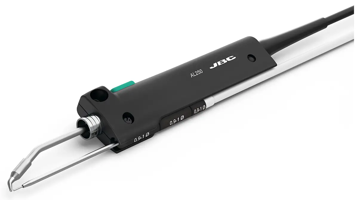
Packing List
The following items are included:
- Auto-Feed Soldering Iron : 1 unit

- Manual : 1 unit

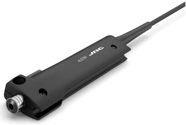
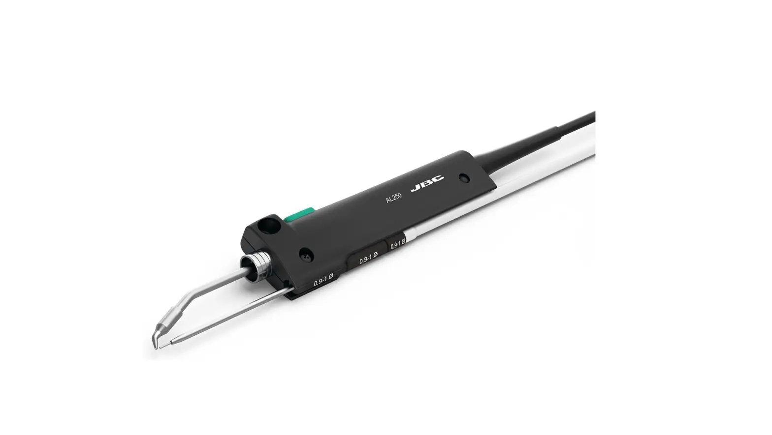
Features and Connections
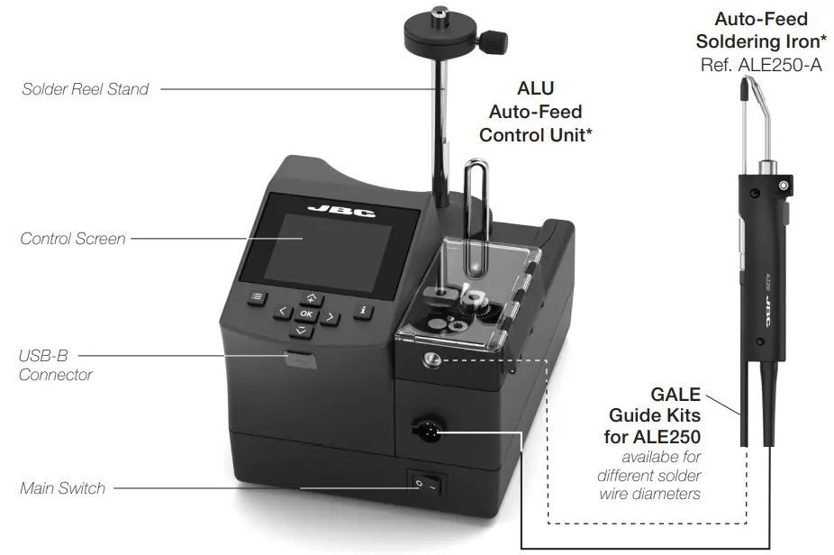
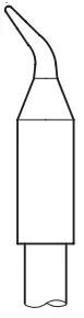
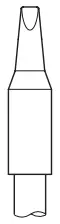
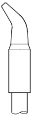
Compatible Cartridges
ALE250 works with C250 cartridges. Find the model that best suits your soldering needs at
www.jbctools.com
- Conical Bent

- Chisel

- Chisel Bent

- Bevel

Tool Assembly
Connect the tool to the control unit following this steps:
Insert and push the guide nozzle until the end (1) and tighten the screw (2). Then connect the tool connector (3).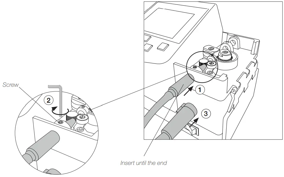
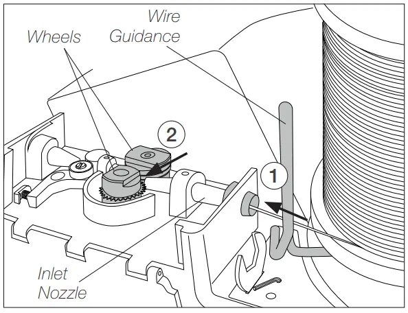
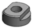
Solder Wire Loading
- Pass the solder wire through the wire guidance and introduce the solder wire into the inlet nozzle (1) until it reaches the wheels (2).

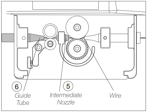
- Make sure the wire passes through the Intermediate Nozzle (5) and enters into the Guide Tube (6).

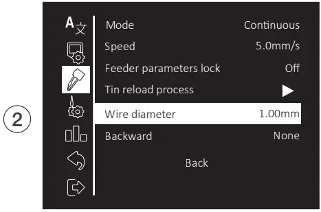
Access to Main Menu by![]() , select “Feeder Settings” (1) and then “Wire Diameter” (2) to adjust the value to the current solder wire diameter.
, select “Feeder Settings” (1) and then “Wire Diameter” (2) to adjust the value to the current solder wire diameter.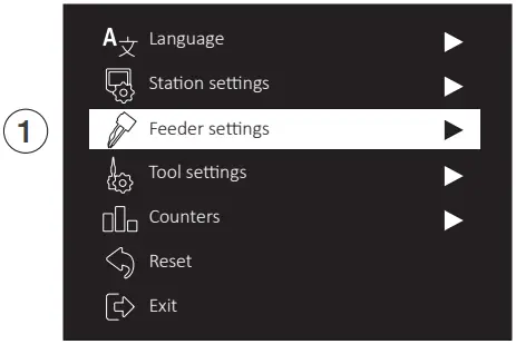
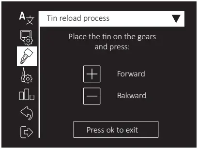
Tin Reloaded Process Screen
Select “Tin Reloaded Process” (1) and then use![]() to feed the solder wire and advance until it comes out through the outlet nozzle. Keep
to feed the solder wire and advance until it comes out through the outlet nozzle. Keep ![]() pressed and after a while the wire will advance faster.
pressed and after a while the wire will advance faster.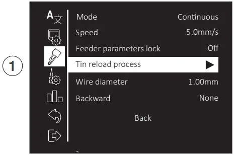
Solder Wire Feeding
Forward the solder wire by pushing the dragging button (4) until the wire comes out of the tip (5).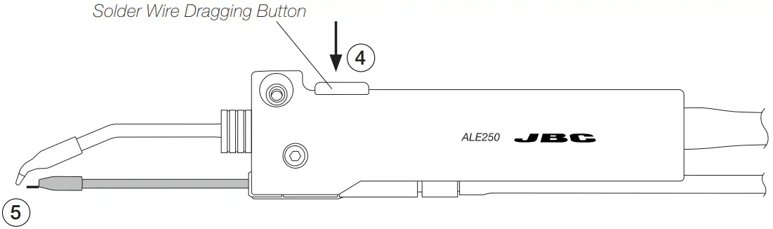
To feed the solder wire, alternatively the pedal P405 can be used. The pedal should be plugged in at the rear of the feeder control unit into the pedal connector.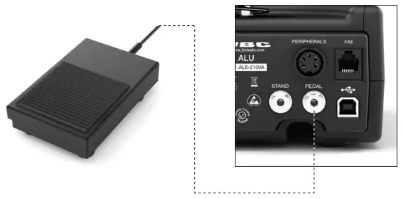
Changing Cartridges
![]() For a safe cartridge change, unplug the tool or turn the station off before following these guidelines:
For a safe cartridge change, unplug the tool or turn the station off before following these guidelines:
Loosen the cartridge screw (1) to release the cartridge (2). Place a new one into the auto feed iron.
Important: It is essential to insert the cartridge till the end for a good connection. Use the mark as reference (3).
Align the tip of the cartridge with the guide nozzle (4) and tighten the cartridge screw (1)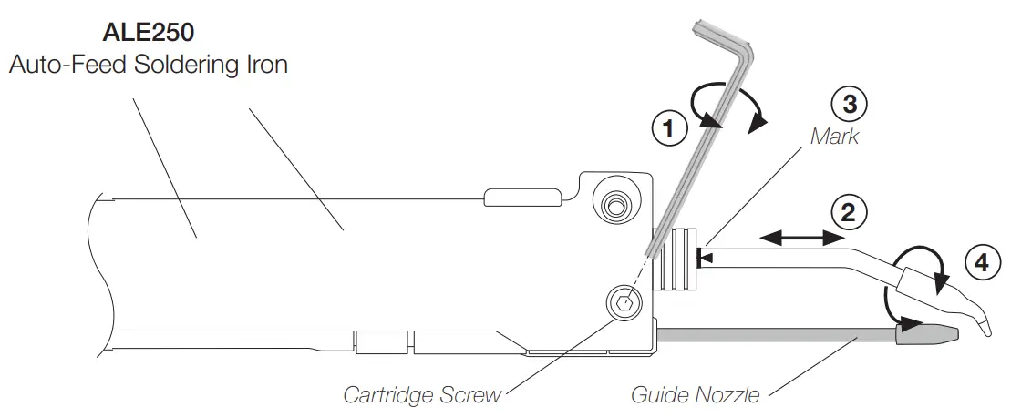
Replacing Guide Sets
Once the tool is disconnected from the control unit and has cooled down, follow these instructions:
Disassemble the outlet nozzle (1) from the guide set.
Loosen the guide set screw (2), take out the guide set (3) and insert the desired one.
Put the outlet nozzle (1) back on again. Leave a gap of 8 to 10 mm (0.31 to 0.39 in) between the cartridge tip and the outlet nozzle (4).
Once the guide nozzle length is adjusted tighten the guide set screw (2).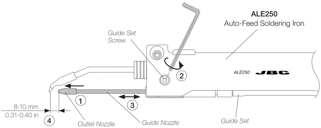
Accessories
GALE Guide Kits for ALE250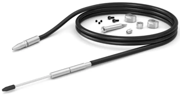
References for GALE Guide Kits without Solder Wire Perforation
| Solder Wire 0 range of use | Guide Kit Ref.  | Guide Set Ref.  | Outlet Nozzle Ref.  | Nozzle Ref. 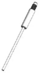 | Traction wheelx Ref. 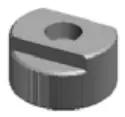 | Support wheel Ref. 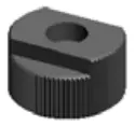 | Inlet nozzle Ref. 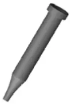 | Interm. Nozzle Ref. 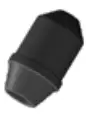 | Counter Wheel Ref. 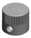 | Screw Ref. 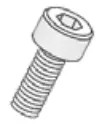 | Headless Screw Ref.  |
| 0.38 – 0.40 mm i 0.015 – 0.016 in | G ALEO4D-A | 0028358 | 0025268 | 0021158 | 0019479 0.90 – 1.10 mm in | 0020345 | 0019520 | 0024954 | 26693 | 0026695 (x2) | 0026696 (x3) |
| 0.46 – 0.56 mm 0.018 – 0.022 in | GALEO5D-A | 0019519 | |||||||||
| 0.60 – 0.64 mm i 0.023 – 0.025 in | G ALEO6D-A | 0022994 | 0025293 | ||||||||
| 0.70 – 0.78 mm i 0.028 – 0.031 in | G ALEO7D-A | 0028359 | 0025289 | 0019480 | 0018632 | 0025291 | |||||
| 0.80 – 0.82 mm 0.032 – 0.033 in i | G ALEO8D-A | 0025270 | 0024955 | ||||||||
| 0.036 – 0.044 | G ALE10D-A | 0028360 | 0021560 | 0024956 | |||||||
| 1.14 – 1.27 mm i 0.045 – 0.051 in | G ALE12D-A | 0028361 | 0025272 | 0019481 | 0024957 | ||||||
| 1.50 – 1.57 mm 0.060 – 0.063 in i | A G LE15D-A | 0028362 | 0025274 | 0024958 | |||||||
| 1.60 – 1.63 mm i 0.063 – 0.065 in | A G LE16D-A | 0028363 | 0025276 | 0028367 | 0024959 | ||||||
| 1.80 mm 0.073 in | GALEI8D-A | 0021559 | 0024960 |
References for GALE Guide Kits with Solder Wire Perforation
| Solder Wire Ø range of use | Guide Kit Ref. | Guide Set Ref. | Outlet nozzle Ref. | Nozzle Ref. | Guide Wheel Ref. | Blade Ref. | Blade Clamp Ref. | Inlet nozzle Ref. | Interm. Nozzle Ref. | Counter Wheel Ref. | Screw Ref. | Headless Screw Ref. |
| 0,8 mm 0,032 in | GALE08V-A | 0028358 | 0025270 | 0021158 | 0021696 | 0021555 | 0018638 | 0018632 | 0024955 | 0026693 | 0026695 (x2) | 0026696 (x3) |
| 1,0 mm 0,040 in | GALE10V-A | 0028359 | 0021560 | 0021699 | 0019170 | 0024956 | ||||||
| 1,2 mm 0,047 in | GALE12V-A | 0028360 | 0025272 | 0023738 | 0019171 | 0024957 |
0026694 | |||||
| 1,5 mm 0,059 in | GALE15V-A | 0028361 | 0025274 | 0019696 | 0024958 | |||||||
| 1,6 mm 0,063 in | GALE16V-A | 0028363 | 0025276 | 0025922 | 0024233 | 0024959 |
Fume Extractor
Ref. F4468 – 2 m (78.74 ft) lenght.
The fume extractor for AL250 is an easy & safe solution to suck the fume generated at the solder joint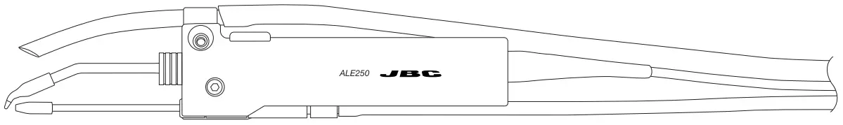
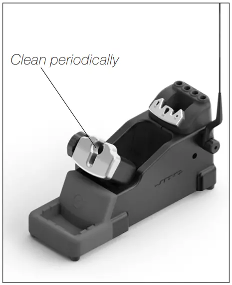
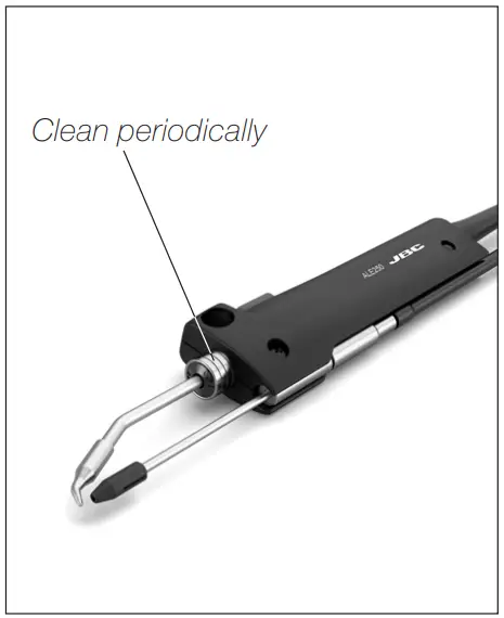
Maintenance
- Before carrying out maintenance, always unplug the stand and the tool.
- Check periodically that the metal parts of the tool and the stand are clean to ensure detection of the tool when it is in the stand. Use a damp cloth or alcohol.
- Periodically check all cables and tubes connections.
- Replace any defective or damaged pieces. Use original JBC spare parts only. Repairs should only be performed by a JBC authorized technical service.

Safety
It is imperative to follow safety guidelines to prevent electric shock, injury, fire or explosion.
- Do not use the tool for any purpose other than soldering or rework.
- The power cord must be plugged into approved bases. Be sure that it is properly grounded before use. When unplugging it, hold the plug, not the wire.
- The tool should be placed in the stand when not in use in order to activate the sleep mode.
The soldering tip, the metal part of the tool and the stand may still be hot even when the station is turned off. Handle with care, including when adjusting the stand position. - Avoid the contact of flux with skin or eyes to prevent irritation.
- Be careful with the fumes produced when soldering.
- Keep your workplace clean and tidy. Wear appropriate protection glasses and gloves when working to avoid personal harm.
- Utmost care must be taken with liquid tin waste which can cause burns.
- This appliance can be used by children over the age of eight and also persons with reduced physical, sensory or mental capabilities or lack of experience provided that they have been given adequate supervision or instruction concerning use of the appliance and understand the hazards involved. Children must not play with the appliance.
- Maintenance must not be carried out by children unless supervised.
Specifications
ALE250
Auto-Feed Soldering Iron
Ref.: ALE250-A
- Total Net Weight: 148 gr / 0.33 lb
- Dimensions: 35 x 21 x 182 mm / 1.42 x 0.83 x 7.16 in
- Solder Wire Diameter: Ø 1 mm / 0.039 in
- Package Dimensions / Weight: 300 x 125 x 65 mm / 257 g
(L x W x H) 11.81 x 4.92 x 2.56 in / 0.57 lb
Complies with CE standards.
ESD safe
Warranty
JBC’s 2 year warranty covers this equipment against all manufacturing defects, including the replacement of defective parts and labour.
Warranty does not cover product wear or misuse. In order for the warranty to be valid, equipment must be returned, postage paid, to the dealer where it was purchased.
Get 1 extra year JBC warranty by registering here:
https://www.jbctools.com/productregistration/ within 30 days of purchase.
 This product should not be thrown in the garbage.
In accordance with the European directive 2012/19/EU, electronic equipment at the end of its life must be collected and returned to an authorized recycling facility.