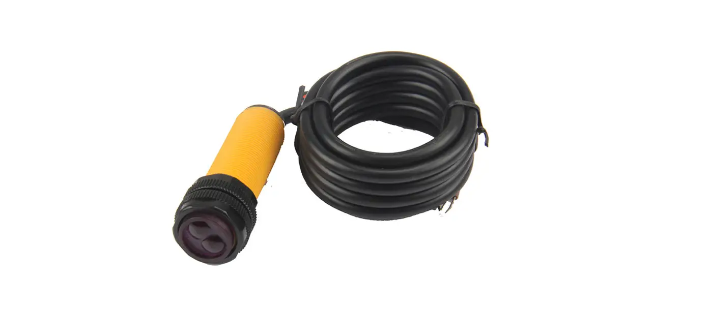
![]() MFE Photo Sensor with Reflector
MFE Photo Sensor with Reflector
User Manual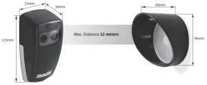
TECHNICAL CHARACTERISTICS
| • Power supply | AC 12/24V – DC 12/24/36V |
| •Consumption | 100mA |
| •Distance | 12 meters |
| •Working Temperature | -25°C – *65°C |
| •Relay Capacity | “Volt-free contacts” |
| •Protection grade | IP54 |
| •Polarization filter | This feature prevents reflections caused by reflective objects. |
LEDs
| Red | Orange | Green | Signal strength |
| No signal | |||
| Low | |||
| Medium | |||
| High |
OPEN THE PHOTOCELL
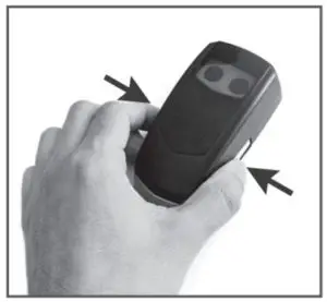 | 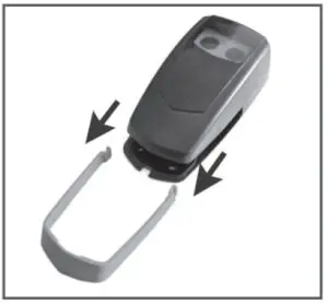 | 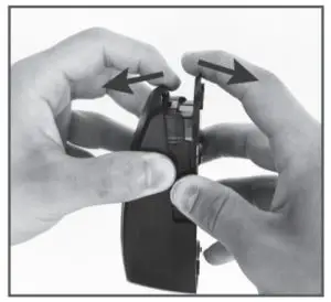 |
| 01 • Press the chrome part in the areas indicated in the image. | 02 • Slide the chrome part | 03 • Open the photocell by separating the pieces from the bottom part. |
INSTALLING THE PHOTOCELL
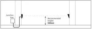
FIXING THE PHOTOCELL
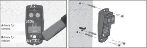
- • Place the photocell base in the desired location so that the power cable passes through the hole in the base.
- • Mark the location of the 3 fixing holes and drill the holes.
- • Secure the photocell with suitable bushings and screws.
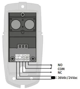
- • Connect the wires to the circuit board (wiring diagram image).
- • Turn on the photocell without placing the photocell cover.
MIRROR PLACEMENT
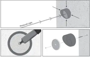
- • Place the mirror in front of the photocell, with the help of the light from the photocell.
- • Make use of the indicator lights to set the best location for fixing the mirror.
- • Mark the location of the fixing hole and drill.
- • Secure the mirror with the appropriate bushing and screw.
PHOTOCELL TUNING
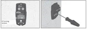
- • If there is no signal, or if the signal is low, use the tuning screws to adjust the direction of the light to increase the signal.
WIRING DIAGRAM
![]() The MFE is designed to protect against any light disturbance. However, too much light can cause unstable conditions with the sensor, such as; strong sunlight directed or reflected exactly in the sensor’s field of view. It is recommended to avoid such installation.
The MFE is designed to protect against any light disturbance. However, too much light can cause unstable conditions with the sensor, such as; strong sunlight directed or reflected exactly in the sensor’s field of view. It is recommended to avoid such installation.
The existence of ice, snow, fog, or smoke can interfere with the operation of the photocell


