
![]() SAFRAN PASSENGER INNOVATIONS
SAFRAN PASSENGER INNOVATIONS
User Manual
RAVE Access Point (RaveAP)
00-5098-01
Document Number:
27-5098-50
Revision 2
| Document Control RELEASED THIS DOCUMENT/DRAWING HAS BEEN ELECTRONICALLY SIGNED IN SPI’S PLM SYSTEM BY THE PERSONS LISTED BELOW. ALL ELECTRONIC SIGNATURES ARE ON FILE IN THE PLM SYSTEM AND ARE FULLY AUDITABLE. | |
| C.O. #: PRN-009919 | Date: 03-Dec-2021 |
| Document Control J. Nimmanant | |
| Technical Checker M. Limbad | Technical Approver A. Rochau |
Copyright © 2021 Safran Passenger Innovations, a Safran Unit composed of Safran Passenger Innovations, LLC and Safran Passenger Innovations Germany GmbH, both subsidiaries of Safran SA. All rights reserved. The contents of this medium are confidential and proprietary to the Unit Safran Passenger Innovations and shall not be disclosed, disseminated, copied, or used except as expressly authorized in writing by Safran Passenger Innovations.
Verify current revision prior to use
REVISION HISTORY
| Rev | By | Description | Date |
| 1 | M. Limbad | Initial Release | 8-APR-2021 |
| 2 | M. Limbad | Added new section “4.1 Regulatory Compliance” | 30-NOV-2021 |
REVISION DETAIL:
For detailed revision history information please view the Item History located in Safran’s Arena PLM.
DOCUMENT SOURCE LOCATION (AT TIME OF AUTHORING):
Arena PLM
PURPOSE
This document provides basic usage and setup information for the Rave Access Point (RaveAP) (P/N: 00-5098-01).
ACRONYMS AND DEFINITIONS
2.1 Acronyms
Table 2-1 Acronyms
| Acronyms | Expansion |
| ARINC | Aeronautical Radio, Incorporated |
| ATP | Acceptance Test Procedure |
| BIOS | Basic Input / Output System |
| BT | Bluetooth |
| CL | CabinLink |
| COTS | Components Off-The-Shelf |
| CPU | Central Processing Unit |
| DMF | Date of Manufacture |
| EUT | Equipment Under Test |
| EEPROM | Electrically Erasable Programmable Read-Only Memory |
| EIRP | Equivalent Isotropic Radiated Power |
| EMC | Electromagnetic Compatibility |
| EMI | Electromagnetic Interference |
| ENV | Environmental |
| ETH | Ethernet |
| GbE | Gigabit Ethernet |
| GND | Ground |
| GPIO | General-Purpose Input / Output |
| GUI | Graphical User Interface |
| HDMI | High-Definition Multimedia Interface |
| I2C | Inter-Integrated Circuit |
| IFE | In-Flight Entertainment |
| IP | Internet Protocol |
| LED | Light-Emitting Diode |
| LRU | Line Replaceable Unit |
| MCB | Main Carrier Board |
| MDIO | Management Data Input / Output |
| NEMA | National Electrical Manufacturers Association |
| NOK | Not OK |
| OEM | Original Equipment Manufacturer |
| PC | Personal Computer |
| PEB | Panel and Ethernet Board |
| PF | Power Factor |
| PHY | Physical Layer |
| PIC | Peripheral Interface Controller |
| PN | Part Number |
| PSB | Power Supply Board |
| PVT | Performance Verification Test |
| RAM | Random Access Memory |
| RAVE | Reliable, Affordable and Very Easy |
| RaveAP | RAVE Access Point |
| Rev | Revision |
| RF | Radio Frequency |
| SN | Serial Number |
| SNMP | Simple Network Management Protocol |
| SPI | Serial Peripheral Interface (bus) |
| SSH | Secure Shell |
| SW | Software |
| TCP | Transmission Control Protocol |
| TTL | Transistor-Transistor Logic |
| UART | Universal Asynchronous Receiver Transmitter |
| USB | Universal Serial Bus |
| UUT | Unit Under Test |
| WAIC | Wireless Avionic Intra-Communications |
| WAN | Wide Area Network |
| WAP | Wireless Access Point |
APPLICABILITY AND REFERENCES
Table 3-1 Applicability and References
| Document Number | Document Name | Source |
| 28-5098-50 | Operational Description, RAVE Access Point (RaveAP) | SPI |
OVERVIEW
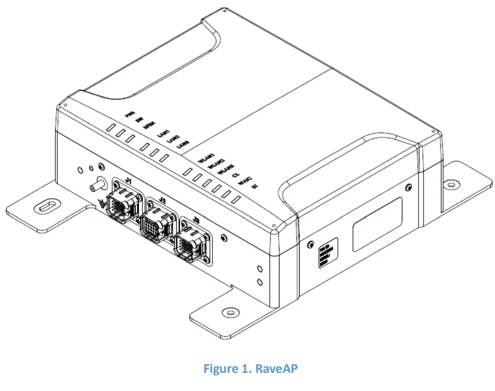
The RaveAP (Figure 1) is a Wireless Access Point (WAP) designed exclusively for usage in aircraft. Airworthiness approvals are typically required for installation and operation of the RaveAP in aircraft.
4.1 Regulatory Compliance
A. USA – Federal Communications Commission (FCC)
This device complies with part 15 of the FCC Rules. Operation is subject to the following two conditions:
- This device may not cause harmful interference, and
- This device must accept any interference received, including interference that may cause undesired operation.
NOTE: This equipment has been tested and found to comply with the limits for a Class A digital device, pursuant to part 15 of the FCC rules. These limits are designed to provide reasonable protection against harmful interference when the equipment is operated in a commercial environment. This equipment generates, uses, and can radiate radio frequency energy and, if not installed and used in accordance with the instruction manual, may cause harmful interference to radio communications. Operation of this equipment in a residential area is likely to cause harmful interference in which case the user will be required to correct the interference at his own expense.
Changes or modifications not expressly approved by the manufacturer could void the user’s authority to operate the equipment.
When using the product, maintain a distance of 20cm from the body to ensure compliance with RF exposure requirements.
B. CANADA – Industry Canada (IC)
This device complies with ISED Canada license-exempt RSS standard(s). Operation is subject to the following two conditions: (1) this device may not cause interference, and (2) this device must accept any interference, including interference that may cause undesired operation of the device. Exposure to radio frequency energy: The radiated output power of this device meets the limits of FCC/ISED Canada radio frequency exposure limits. This device should be operated with a minimum separation distance of 20 cm (8 inches) between the equipment and a person’s body.
CAN ICES-003(A) / NMB-003(A)
PRODUCT FEATURES
The RaveAP features multiple radios to enable wireless onboard communication.
| Radio | Technology | Intended Usage |
| 1 – Wi-Fi 1 | 2.4 GHz Wi-Fi | Passenger/Crew Wi-Fi Communication |
| 2 – Wi-Fi 2 | 5 GHz Wi-Fi | Passenger/Crew Wi-Fi Communication |
| 3 – Wi-Fi 3 | Dual Band 2.4/5 GHz Wi-Fi | Scanning & Monitoring |
| 4 – Cabin Link (CL) | 2.4 GHz – 802.15.4 | Machine-to-Machine Communication |
| 5 – Bluetooth (BT) | 2.4 GHz Bluetooth | Bluetooth Beacons |
INTERFACES
6.1 Ethernet
The RaveAP has three GigE-capable (10/100/1000 Base-T Ethernet) data ports available via connectors J1, J2, and J3.
6.2 Power
The RaveAP is powered by 115V AC, 350-800 Hz on J1 or J2.
6.3 Discrete Interfaces
The RaveAP features two (2) discrete inputs to enable power (POWER_ON) and to enable radios (RF_ENABLE) on J1 and J2. The discrete are active when connected to the ground (GND).
6.4 IP Configuration
The RaveAP features four (4) IP Pin straps on J3 to assign IP addresses to a RaveAP based on physical aircraft location. The configuration of these straps is aircraft specific.
6.5 LEDs
The RaveAP features twelve (12) status LEDs.
| LED | Status |
| PWR | Power status of RaveAP |
| SW | Software Status of RaveAP |
| RFEN | RF status of radios (LED-lit = radios enabled) |
| LAN1 | Link/activity status of Ethernet interface ETH1 |
| LAN2 | Link/activity status of Ethernet interface ETH2 |
| LAN3 | Link/activity status of Ethernet interface ETH3 |
| WLAN1 | Radio status of Wi-Fi radio 1 |
| WLAN2 | Radio status of Wi-Fi radio 2 |
| WLAN3 | Radio status of Wi-Fi radio 3 |
| CL | Radio status of Cabin Link radio |
| WAIC | Not used (permanently OFF) |
| BT | Radio status of Bluetooth radio |
6.6 Pinout
Table 2 shows the pinout of the RaveAP.
| J1 | J2 | J3 | ||||||
| POS | ASSIGNMENT | DIRECTION | POS | ASSIGNMENT | DIRECTION | POS | ASSIGNMENT | DIRECTION |
| 1 | ETH 1 BI DB+ | BIDIRECTIONAL | 1 | ETH 2 BI DA+ | BIDIRECTIONAL | 1 | DISC IN CONF STRAP_0 | IN |
| 2 | ETH 1 BI DA+ | BIDIRECTIONAL | 2 | ETH 2 BI DB+ | BIDIRECTIONAL | 2 | DISC IN CONF_STRAP_1 | IN |
| 3 | SHIELD QUAD 1 | GROUND | 3 | SHIELD QUAD 1 | GROUND | 3 | DISC_IN CONF_STRAP_2 | IN |
| 4 | ETH 1 81 DD+ | BIDIRECTIONAL | 4 | ETH 2 81 DC+ | BIDIRECTIONAL | 4 | DISC IN CONF STRAP 3 | IN |
| 5 | ETH 1 81 DC+ | BIDIRECTIONAL | 5 | ETH 2 BI DD+ | BIDIRECTIONAL | 5 | N/C | N/A |
| 6 | ETH 1 BI_DA- | BIDIRECTIONAL | 6 | ETH 2 BI DB- | BIDIRECTIONAL | 6 | DISC IN CONF STRAP GND 0 | GROUND |
| 7 | ETH 1 BIDB- | BIDIRECTIONAL | 7 | ETH 2 BI DA- | BIDIRECTIONAL | 7 | DISC IN CONF STRAP GND 1 | GROUND |
| 8 | SHIELD QUAD 2 | GROUND | 8 | SHIELD QUAD 2 | GROUND | 8 | DISC IN CONF STRAP GND 2 | GROUND |
| 9 | ETH 1 BI_DC- | BIDIRECTIONAL | 9 | ETH 2 BI DD- | BIDIRECTIONAL | 9 | DISC IN CONF STRA-P_GND_3 | GROUND |
| 10 | ETH 1 BI DD- | BIDIRECTIONAL | 10 | ETH 2 BI_DC- | BIDIRECTIONAL | 10 | N/C | N/A |
| 11 | N/C | N/A | 11 | N/C | N/A | 11 | ETH 3 BI DB+ | BIDIRECTIONAL |
| 12 | POWER ON | IN | 12 | POWER ON | OUT | 12 | ETH 3 81 DA+ | BIDIRECTIONAL |
| 13 | N/C | N/A | 13 | N/C | N/A | 13 | SHIELD QUAD 1 | GROUND |
| 14 | SIGNAL GND | GROUND | 14 | SIGNAL GND | GROUND | 14 | ETH 3 BI DD+ | BIDIRECTIONAL |
| 15 | RF ENABLE | IN | 15 | RF ENABLE | OUT | 15 | ETH 3 81 DC+ | BIDIRECTIONAL |
| 16 | 115V AC RETURN | GROUND | 16 | 115V AC RETURN | GROUND | 16 | ETH 3 81 DA- | BIDIRECTIONAL |
| 17 | CH GND | GROUND | 17 | CH GND | GROUND | 17 | ETH 3 BI_DB- | BIDIRECTIONAL |
| 18 | 115VAC | IN | 18 | 115VAC | OUT | 18 | SHIELD QUAD 2 | GROUND |
| 19 | N/C | N/A | 19 | N/C | N/A | 19 | ETH 3 BI DC- | BIDIRECTIONAL |
| 20 | N/C | N/A | 20 | N/C | N/A | 20 | ETH 3 81 DD- | BIDIRECTIONAL |
Table 2. RaveAP Pinout.
SETUP
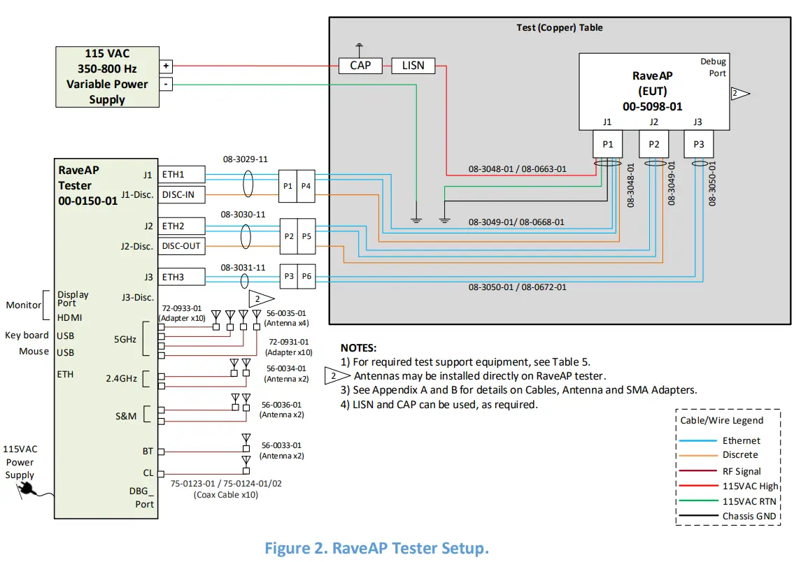
The RaveAP is typically part of a larger aircraft installation with a control and management server and aircraft-specific configurations. To facilitate a laboratory test setup, a RaveAP Tester (P/N: 00-0150-01) is available. Figure 2 shows how to set up the RaveAP with the RaveAP Tester.
A 115V AC/400 Hz power supply is required to power the RaveAP. The RaveAP Tester can be powered from the standard mains power.
To access and control the RaveAP Tester, a commercially available USB keyboard and mouse, as well as an HDMI or DisplayPort-capable monitor, are required.
The RaveAP Tester contains the necessary software to control the RaveAP and execute standard test cases. Refer to document 28-5098-50 for more details.
As the RaveAP supports multiple radios, the operating frequencies must be chosen such that the frequencies do not interfere with each other for optimal performance.
| Radio | Channel (Bandwidth) | Centre Frequency |
| 1 – Wi-Fi 1 | 6 (20 MHz) | 2437 MHz |
| 2 – Wi-Fi 2 | 46 (40 MHz) | 5230 MHz |
| 3 – Wi-Fi 3 | 159 (40 MHz) | 5795 MHz |
| 4 – Cabin Link (CL) | 25, 26 (2 MHz) | 2475, 2480 MHz |
| 5 – Bluetooth (BT) | 37, 38, 39 (2 MHz) | 2402, 2426, 2480 MHz |
Table 3. Typical Radio Channel Configuration.
27-5098-50 Revision 2
Safran Passenger Innovations – Proprietary and Confidential
Verify current revision prior to use
 Access Point User Manual")


