
Suzhou Etag Technology ETAP03 Access Point

Product parameters
| Item | Parameter value | Note |
| Type | ETAP03 | |
| Structure size | 190mm(H)×190mm(V)×39mm(D) | |
| Weight | 285g | |
| Appearance color | white | |
| Operating voltage | DC 5V | Please use the original power supply |
| Operating current | less than 200mA | |
| Communication Mode | 2.4G | |
| Communication distance | 20-50 meters | |
| Data Interface | Standard network cable interface | |
| Storage temperature range | -20℃~70℃ | |
| Humidity | 45%~70%RH |
Product introduction
Upside
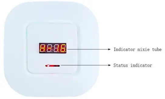
Status indicator: Working status indication (R / Y / B)
- LED_ R: Power indicator
- LED_ Y: Work indicator
- LED_ B: Work indicator
Indicator nixie tube: Working status indication and Access Point number indication
- H: Idle
- C: Busy
- —-: Offline
Backside
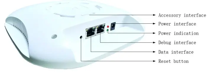
- Power interface: DC 5V standard power supply
- Power indication: The two lights are always on, indicating that the power supply of the Access Point is normal.
- Debug interface: The one close to the power supply port, DO NOT USE.
- Data interface: The one far away from the network port, UTP / STP of category 5 or above shall be used.
- Network port left to light: network port power indicator
- Network port right light: act/link indicator
- Reset button: Long press this button until the yellow, blue and red indicators on the front of the Access Point flash at the same time, indicating that the Access Point is reset successfully, and the factory default settings are restored.
- Accessory interface: Used with ceiling installation accessories.
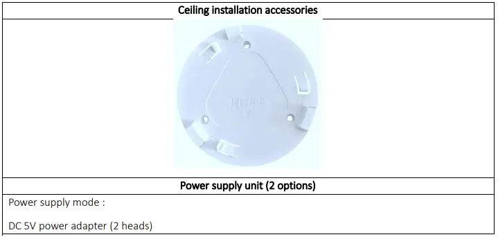
Accessories in the box
Configuration description
Hardware environment setup
The initial configuration requires power supply to the Access Point and direct connection to the local computer through network cable.
Connection mode
- The power adapter -> the Access Point power port
- The Access Point data port -> the computer network port by network cable.
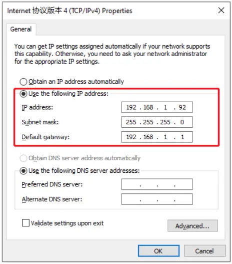
Network environment settings
IP address configuration
Default IP address of Access Point
Local IP address:192.168.1.100
Destination IP address:192.168.1.92
The default configuration of the corresponding network card connected to the Access Point is shown in the figure below, which is set as the default destination IP address.
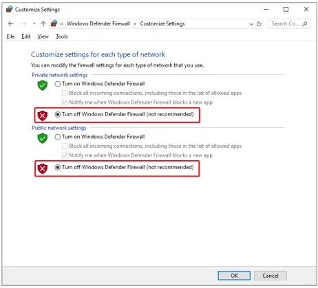
Turn off windows firewall
Default IP configuration modification
If you need to modify the default IP configuration of the Access Point, you need to do the following.
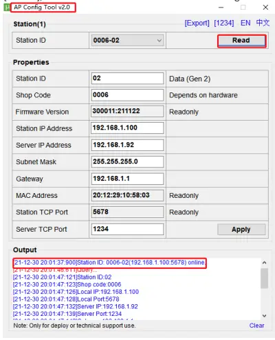
- Open the Access Point configuration tool [AP config tool], confirm that the Access Point is online [Online], and click “Read” to read the current configuration information of the Access Point.

- Modify the current configuration information as needed, as described below. After modification, click “Apply” button to complete the update.
Configuration item Default value Configuration description Access Point ID
01
In the same network environment, the Access Point ID needs to be accumulated according to the number of Access Points, such as 01, 02, etc.
Store number 0001 A four-digit store number created or assigned by the the electronic price tag system, such as 0001,0002, etc.
Version 300011:211122 Read-only Access Point IP address
192.168.1.100 Access Point local IP address Computer IP address
192.168.1.92 IP address of the computer connected to the Access Point
Subnet mask 255.255.255.0 Subnet mask of the upper gateway of the local network of the Access Point
Gateway 192.168.1.1 Upper gateway address of local network of Access Point
Network address 20:20:02:24:13:11 Read-only Local Access Point port
5678 Read-only Target server port 1234 The online port of the Access Point set on the electronic price tag software
Note:
if the Access Point is configured incorrectly, the Access Point needs to be reset. After reset, the Access Point will restore the default configuration.
Communication mode
The cloud sends the specified label data to the Access Point, which sends the Specified Label (Mac address) via a 2.4g private communication protocol. When the label and the Access Point establish a communication connection, the image data is updated. At the end of the update, the tag will upload the communication status to the Access Point. After the completion of communication all the tags, the Access Point collects all of the tags’ response information to the cloud.
FCC Statement
Any Changes or modifications not expressly approved by the party responsible for compliance could void the user’s authority to operate the equipment. This device complies with part 15 of the FCC Rules. Operation is subject to the following two conditions:
- This device may not cause harmful interference, and
- This device must accept any interference received, including interference that may cause undesired operation.
Note:
This equipment has been tested and found to comply with the limits for a Class B digital device, pursuant to part 15 of the FCC Rules. These limits are designed to provide reasonable protection against harmful interference in a residential installation. This equipment generates, uses and can radiate radio frequency energy and, if not installed and used in accordance with the instructions, may cause harmful interference to radio communications. However, there is no guarantee that interference will not occur in a particular installation. If this equipment does cause harmful interference to radio or television reception, which can be determined by turning the equipment off and on, the user is encouraged to try to correct the interference by one or more of the following measures:
- Reorient or relocate the receiving antenna.
- Increase the separation between the equipment and receiver.
- Connect the equipment into an outlet on a circuit different from that to which the receiver is connected.
- Consult the dealer or an experienced radio/TV technician for help.
FCC Radiation Exposure Statement:
This equipment complies with FCC radiation exposure limits set forth for an uncontrolled environment. This equipment should be installed and operated with a minimum distance 20cm between the radiator& your body.

 Access Point User Manual")


