![]() ENGINEERING
ENGINEERING
TOMORROW
Installation Guide
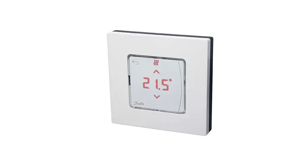
Danfoss Icon2™ / 24V RT
Room Thermostat
Installation
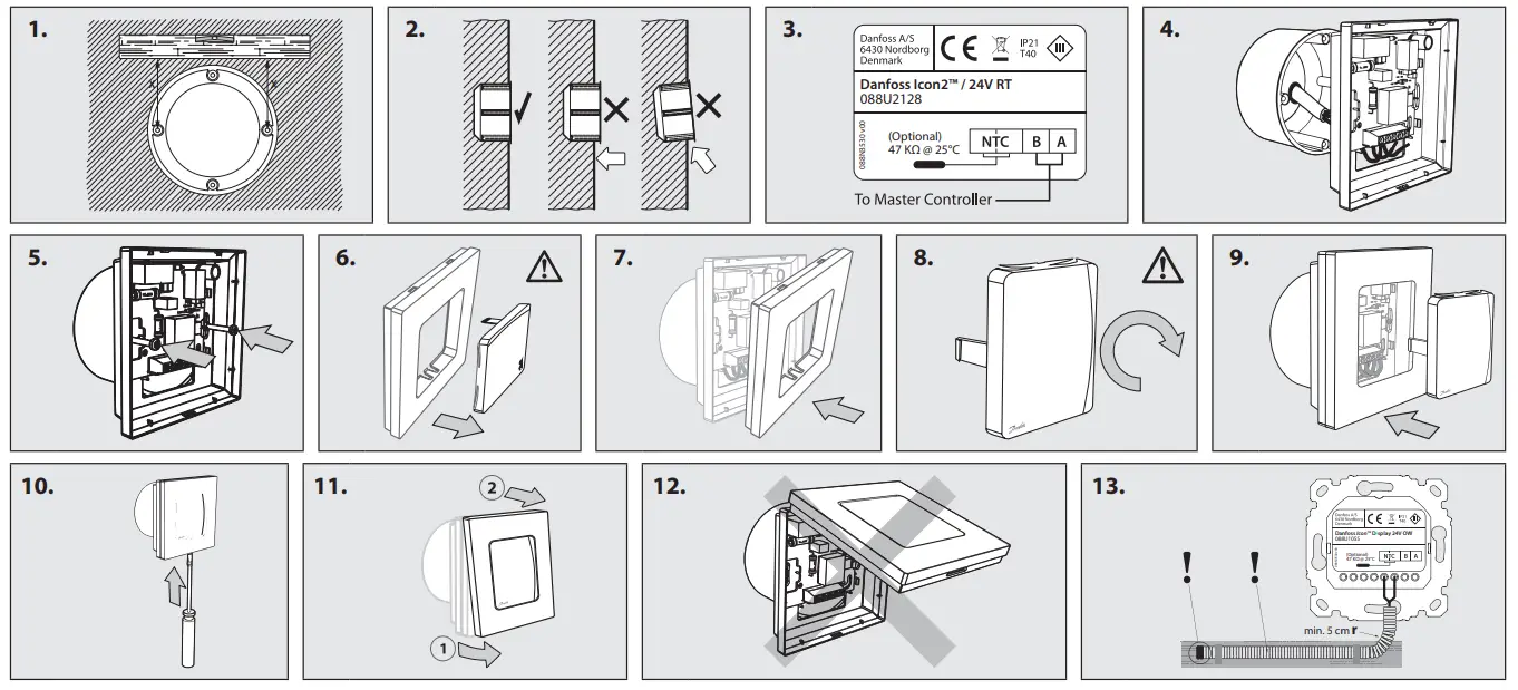
Follow the illustrations fig. 1 to 9 (dismantling, see fig. 10 to 12).
Note, fig. 3: Thermostats can be wired in either BUS or Star configuration, see Master Controller Installation Guide for more information.
Note, fig. 13: Optional floor sensor requires use of an electrical conduit!
Touch and hold ![]() to access the Settings Menu. In Settings Menu, touch and hold
to access the Settings Menu. In Settings Menu, touch and hold ![]() to access the Installer Menu.
to access the Installer Menu.
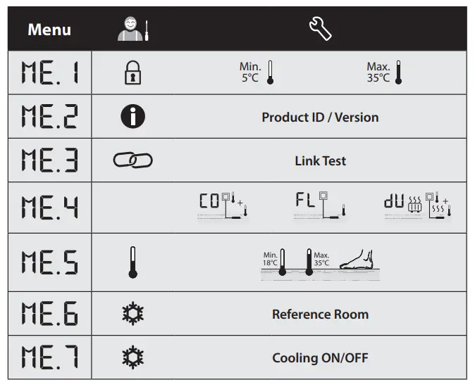
![]() : Range limitation of setpoint for room temperature.
: Range limitation of setpoint for room temperature.![]() : Info/version number, can be used to identify products.
: Info/version number, can be used to identify products.![]() : Perform Link Test of connection with Master Controller. Returns result as 0-100% (80% or higher is a very strong connection).
: Perform Link Test of connection with Master Controller. Returns result as 0-100% (80% or higher is a very strong connection).![]() : Floor sensor mode:
: Floor sensor mode:![]() = Comfort mode. Both air- and floor sensor is used.
= Comfort mode. Both air- and floor sensor is used.![]() = Floor sensor mode. The end user sets desired floor temperature.
= Floor sensor mode. The end user sets desired floor temperature.![]() = Dual mode. The thermostat controls a radiator and floor heating circuit(s). Floor heating circuits assures min. floor temperature and the radiator is used for peak load.
= Dual mode. The thermostat controls a radiator and floor heating circuit(s). Floor heating circuits assures min. floor temperature and the radiator is used for peak load.![]() : Min. and max. temperature for floor, used in
: Min. and max. temperature for floor, used in![]() and
and![]() mode.
mode.![]() : Reference Room. Set to ON, if you want this thermostat to be the reference thermostat for switching between cooling and heating.
: Reference Room. Set to ON, if you want this thermostat to be the reference thermostat for switching between cooling and heating.![]() : Cooling ON/OFF. Use to turn off the ability to cool, in e.g. bath rooms.
: Cooling ON/OFF. Use to turn off the ability to cool, in e.g. bath rooms.
13866 000 02 Manual Installation WRT SI F86 OW


