
OSS-KIT-EXP-6002 Host Server to Expansion System Kit
Overview
Description
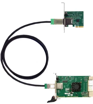
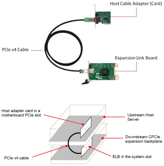
The PCIe x4 expansion kit is used to extend the PCI express bus from a host server to an external expansion chassis. The host adapter card inserts into a PCIe slot of the server. It then cables to a downstream expansion link board (ELB). The ELB acts as a downstream cable link board and the primary fan-out switch to support multiple configurations of PCI express expansion slots. The host adapter installs into a PCIe x4, x8 or x16 slot on the host motherboard. It then cables to the expansion link board and installs in the SHB or system slot of a CPCIe backplane.
Features
Adapter Cards
- The Host adapter card inserts into any PCI Express x4, x8, 16 slot on the host motherboard.
- The Target adapter card fits into SHN slot of PICMG 1.3 backplane..
- Support half-height bracket.
- The Host and Target cable adapter cards require no software / drivers
x4 Link Cable
- Available in 1m, 2m, 3m, 5m, 7m lengths.
- PCI-SIG Express Cable Specification Compliant.
- Includes x4 PCIe lane and side-band signals for:
- Power ON
- Reset
- PCIe clock
- Cable Present
- Wake
- Positive latching mechanism per PCI-SIG specification
- Support 10 Gbps full-duplex transfer rates.
Specifications
Host Adapter
| PCIe x4 Host Cable Adapter Card (SKU : OSS-PCIe-HIB25-X4-H) | |
| Form Factor | PCIe x4 add-in card |
| Dimension (H x L) | 2.7” x 3.1” (68 x 78mm) |
| Front Panel Connectors | One PCIe x4 cable connectors |
| Front Panel Indicators | Power ON / Cable Present LED |
| Red-drivers | Pericom P12EQX5804 |
| Temperature Range | 0° to 50°C (32° to 122°F) |
| Relative Humidity | 10 to 90% non-condensing |
| Shock | 30g Acceleration peak (11 ms pulse) |
| Vibration | 5-17 Hz 0.5” double amplitude displacement; 7-2000Hz, 1.5g acceleration |
| Power Consumption | 3.75W typical, [email protected] |
| Agency Compliance | UL60950, FCC Class B, CE safety and emissions, ROHS |
| Redriver | Pericom P12EQX5804 |
Expansion Link Board
| PCIe x4/x8 Gen2 Expansion Link Board (SKU : OSS-SHB-G2-x8-x4) | |
| Form Factor | PCIMG EXP.system slot compliant. Single Slot |
| Slot Type | System slot for the expansion chassis |
| Dimension (H x L) | 3.937 x 6.299 in (100 x 160 mm), 1 slot wide |
| Switch | PLX PEX8733 32 lane switch |
| Upstream Interface | x4 PCI Express over cable PCI-SIG PCI Express Cable Rev 2.0 Compliant |
|
Downstream Interface | 16 lanes of PCI Express on the backplane connectors. The lanes form two or four links to the backplane through the XP2 and XP3 connectors per the PICMG EXP.0 specification. The following link modes are automatically selected by the backplane as follows: • Two link mode: 2 x8 links (per backplane capabilities) • Four link mode: Four x4 PCIe links |
| Front Panel Connectors | 1 PCIe x4 Cable (Molex : 75586-0010) |
| Front Panel Indicators | 4 backplane link-active indicators (green) 2 or 4 link mode + cable link (green) |
| Power Consumption | 10W typical +12V @ .5, 3.3V @ 1.25A, 5Vaux @ 2.5mA |
| Temperature Range | 0° to 50°C (32° to 122°F) |
| Relative Humidity | 10 to 90% non-condensing |
| Storage Temperature | -40° to 85°C (-40°-185°F) |
| Shock | 30g acceleration peak (11ms pulse) |
| Vibration | 5-17 Hz 0.5” double amplitude displacement; 7-2000Hz, 1.5g acceleration |
| Agency Compliance | UL60950, FCC Class B, CE safety and emissions, ROHS |
PCIe x4 Cable
| PCIe x4 Cable (SKU : OSS-PCIe-CBL-x4.1M) 1 meter long cable | |
| Cable Length | 1m, 2m, 3m, 5m, 7m |
| Circuits loaded | 38 |
| Gender | Male-to-Male |
| Lock to Mating Part | Yes |
| Material-Metal | Zinc Alloy |
| Pitch-Mating Interface | 0.80mm (0.31) |
| Single Ended | No |
| Water proof / Dust proof | Yes |
| Wire Insulator Diameter | N/A |
| Wire Size AWG | 28 |
| Wire / Cable Type | Round |
| Electrical Current | 1A Max per contact |
| Shielded | Yes |
| Voltage-Maximum | 30V DC |
Component Identification
Host cable adapter card
The PCIe x4 expansion kit contains two cable adapter boards, the host cable adapter and the target cable adapter. The host adapter inserts into the host computer’s PCIe x4, x8 or x16 slot.
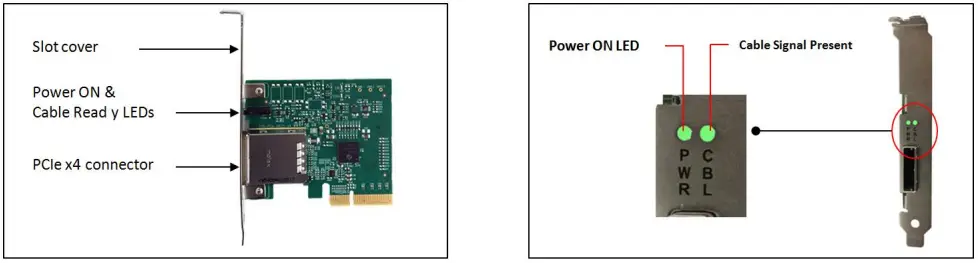
Cable LED indicators are the same for both Host and Target configurations.
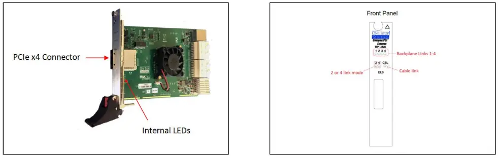
Expansion Link Board
The Expansion Link Board (ELB) OSS-CPCIe3-3U/6U-ELB-x4 is a downstream link board that installs into a CPCIe chassis. The ELB fits into the system slot of a CPCIe backplane. The ELB is the downstream link board and the primary fan-out switch to support multiple configurations of CPCI or CPCIe expansion slots.
Installation Instructions
Installing the Adapter Kit
Insert the host cable adapter into an appropriate PCIe slot of the host computer. For example, a PCIe x4 host board can be inserted into a PCIe x16, x8, or x4 slot. It will still operate at x4 speeds. Secure the cable adapter card
Expansion link board
- Insert the expansion link board into the SHB slot on the chosen backplane.
- Connect the x4 PCIe cable to both cables adapter cards. Press or pull the green TAB while slowly inserting the cable, then release it to lock the cable. See photos below

- Test by pulling back on the connector.
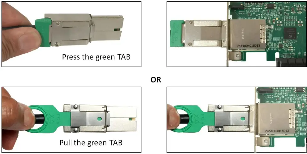
Removing PCIe Cable
To remove the cable, press or pull the green tab and slowly pull the cable out.
Operation
- Plug in expansion system and turn the power supply on.
- Power up host computer.
- The expansion system will power up.
Technical Information
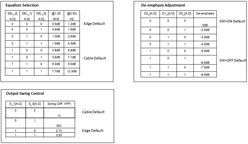
The transmit and receive signals on the OSS-HIB-25×4 are driven and conditioned by Pericom redriver chips. Adjustments can be made to equalization, de-emphasis and output swing. These controls are factory set by the use of zero Ohm resistors.
In the following tables, a 0 indicates that a zero Ohm resistor has been installed and a 1 indicates no resistor. In rare cases, mostly where non-OSS equipment is used with the HIB-25×4, these adjustments may need to be changed. The following tables are made available for this purpose. It is highly recommended to contact OSS customer support before making changes to these settings. Having the customer solder to the board should void the warranty.
Signal Adjustment
Pin Assignments
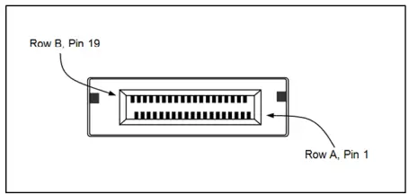
Host and Target card connectors (x4 Card Edge Connector)
- The pins are numbered as shown with side A on the top of the centerline on the solder side of the board and side B on the bottom of the centerline on the component side of the board.
- The PCIe interface pins PETpx, PETnx, PERpx, and PERnx are named with the following convention: “PE” stands for PCIe high speed, “T” for Transmitter, “R” for Receiver, “p” for positive (+), and “n” for negative (-).
- Note that adjacent differential pairs are separated by two ground pins to manage the connector crosstalk.
Pin-out for the PCIe x4 Card Edge Connector on the “Host Cable Adapter”
|
Pin # | Side B | Side A | ||
| Name | Description | Name | Description | |
| 1 | N/C | N/C | PRSNT1# | Hot-Plug presence detect |
| 2 | N/C | N/C | N/C | N/C |
| 3 | N/C | N/C | N/C | N/C |
| 4 | GND | Ground | GND | Ground |
| 5 | NC | N/C | N/C | Not connected |
| 6 | N/C | N/C | JTAG3 | TDI (Test Data Input) |
| 7 | GND | Ground | JTAG4 | TDO (Test Data Output) |
| 8 | +3.3V | 3.3 V power | N/C | Not connected |
| 9 | N/C | Not connected | N/C | Not connected |
| 10 | 3.3Vaux | 3.3 V auxiliary power | +3.3V | 3.3 V power |
| 11 | N/C | N/C | PERST# | Fundamental reset |
| Mechanical key | ||||
| 12 | RSVD | Reserved | GND | Ground |
| 13 | GND | Ground | REFCLK+ | Reference clock (differential pair) |
| 14 | PETp0 | Transmitter differential pair, Lane 0 | REFCLK | |
| 15 | PETn0 | GND | Ground | |
| 16 | GND | Ground | PERp0 | Receiver differential pair, Lane 0 |
| 17 | PRSNT2# | Hot-Plug presence detect | PERn0 | |
| 18 | GND | Ground | GND | Ground |
| 19 | PETp1 | Transmitter differential pair, Lane 1 | RSVD | Reserved |
| 20 | PETn1 | GND | Ground | |
| 21 | GND | Ground | PERp1 | Receiver differential pair, Lane 1 |
| 22 | GND | Ground | PERn1 | |
| 23 | PETp2 | Transmitter differential pair, Lane 2 | GND | Ground |
| 24 | PETn2 | GND | Ground | |
| 25 | GND | Ground | PERp2 | Receiver differential pair, Lane 2 |
| 26 | GND | Ground | PERn2 | |
| 27 | PETp3 | Transmitter differential pair, Lane 3 | GND | Ground |
| 28 | PETn3 | GND | Ground | |
| 29 | GND | Ground | PERp3 | Receiver differential pair, Lane 3 |
| 30 | RSVD | Reserved | PERn3 | |
| 31 | PRSNT2# | Hot-Plug presence detect | GND | Ground |
| 32 | GND | Ground | RSVD | Reserved |
Notes:
- Optional signals that are not implemented are left as no connects on the board side connector.
- Reserved signals are no connects on the board side connector.
- Although support of CWAKE# is optional from the board side connector perspective, an allocated wire is mandated for the cable assembly.
- Board side pin-outs on both sides of the Link are identical. The cable assembly incorporates a null modem for the PCIe transmit and Board side pin-outs on both sides of the Link are identical. The cable assembly incorporates a null modem for the PCIe transmit and
PCI Express x4 Connector PIN Assignment
Pin-out for the PCIe x4 Cable
| Pin # | Cable Side 1 | Cable Side 2 | Pin # | |
| A1 A4 A7 A10 A13 A16 B1 B4 B7 B10 B13 | GND | Drain Wires | GND | A1 A4 A7 A10 A13 A16 B1 B4 B7 B10 B13 |
| A2 | PETp0 | Differential Pair | PERp0 | B2 |
| A3 | PETn0 | PERn0 | B3 | |
| A5 | PETp1 | Differential Pair | PERp1 | B5 |
| A6 | PETn1 | PERn1 | B6 |
| Pin # | Cable Side 1 | Cable Side 2 | Pin # | |
| A8 | PETp2 | Differential Pair | PERp2 | B8 |
| A9 | PETn2 | PERn2 | B9 | |
| A11 | PETp3 | Differential Pair | PERp3 | B11 |
| A12 | PETn3 | PERn3 | B12 | |
| A14 | CREFCLK+ | Differential Pair | CREFCLK+ | A14 |
| A15 | CREFCLK | CREFCLK- | A15 | |
| A17 | SB_RTN | Hook-up Wire | SB_RTN | A17 |
| A18 | CPRSNT# | Hook-up Wire | CPRSNT# | A18 |
| A19 | CPWRON | Hook-up Wire | CPWRON | A19 |
| B2 | PERp0 | Differential Pair | PETp0 | A2 |
| B3 | PERn0 | PETn0 | A3 | |
| B5 | PERp1 | Differential Pair | PETp1 | A5 |
| B6 | PERn1 | PETn1 | A6 | |
| B8 | PERp2 | Differential Pair | PETp2 | A8 |
| B9 | PERn2 | PETn2 | A9 | |
| B11 | PERp3 | Differential Pair | PETp3 | A11 |
| B12 | PERn3 | PETn3 | A12 | |
| B14 | PWR | NC | PWR | B14 |
| B15 | PWR | NC | PWR | B15 |
| B16 | PWR_RTN | NC | PWR_RTN | B16 |
| B17 | PWR_RTN | NC | PWR_RTN | B17 |
| B18 | CWAKE# | Hook-up Wire | CWAKE# | B18 |
| B19 | CPERST# | Hook-up Wire | CPERST# | B19 |
| Back shell | Chassis Ground | Overall Cable Braid | Chassis Ground | Back shell |
Signal Descriptions
| PETp(x) | PCI Express Transmit Positive signal of (x) pair. |
| PETn(x) | PCI Express Transmit Negative signal of (x) pair. |
| PERp(x) | PCI Express Receive Positive signal of (x) pair. |
| PERn(x) | PCI Express Receive Negative signal of (x) pair. |
| CREFCLK+/- | Cable REFerence CLocK: Provides a reference clock from the host system to the remote system. |
| SB_RTN | Side Band ReTurN: return path for single ended signals from remote systems. |
| CPRSNT# | Cable PReSeNT: Indicates the presence of a device beyond the cable. |
| PWR | PoWeR: Provides local power for in-cable redriver circuits. Only needed on long cables. Power does not go across the cable.) |
| PWR_RTN | PoWeR ReTurN: Provides local power return path for PWR pins. |
| CWAKE# | Cable WAKE |
| CPERST# | Cable PCI Express Reset |
Connector Pin-outs for the PCIe x4 Cable Connector
| PIN# | SIGNAL | DESCRIPTION |
| A1 | GND | Ground reference |
| A2 | PETp0 | Differential PCI Express Transmitter Lane 0 |
| A3 | PETn0 | |
| A4 | GND | Ground reference |
| A5 | PETp1 | Differential PCI Express Transmitter Lane 1 |
| A6 | PETn1 | |
| A7 | GND | Ground reference |
| A8 | PETp2 | Differential PCI Express Transmitter Lane 2 |
| A9 | PETn2 | |
| A10 | GND | Ground reference |
| A11 | PETp3 | Differential PCI Express Transmitter Lane 3 |
| A12 | PETn3 | |
| A13 | GND | Ground reference |
| A14 | CREFCLK+ | Differential 100MHz cable reference clock |
| A15 | CREFCLK- | |
| A16 | GND | Ground reference |
| A17 | SB_RTN | Side Band Return |
| A18 | CPRSNT# | Used for detection of external cable and if downstream system is powered |
| A19 | CPWRON | Turns power on / off to slave type downstream subsystems |
| B1 | GND | Ground reference |
| B2 | PERp0 | Differential PCI Express Receiver Lane 0 |
| B3 | PERn0 | |
| B4 | GND | Ground reference |
| B5 | PERp1 | Differential PCI Express Receiver Lane 1 |
| B6 | PERn1 | |
| B7 | GND | Ground reference |
| B8 | PERp2 | Differential PCI Express Receiver Lane 2 |
| B9 | PERn2 | |
| B10 | GND | Ground reference |
| B11 | PERp3 | Differential PCI Express Receiver Lane 3 |
| B12 | PERn3 | |
| B13 | GND | Ground reference |
| B14 | PWR | +3.3V Cable Power |
| B15 | PWR | |
| B16 | PWR_RTN | Cable Power Return |
| B17 | PWR_RTN | |
| B18 | CWAKE# | Power management signal for wakeup events (optional) |
| B18 | CPERST# | Cable Reset# |
PCI Express x4 Connector PIN Assignment
| CFG(0:2) | BP PORT CFG | ||||||
| 0 | 1 | 2 | A0 | A1 | A2 | A3 | B0 |
| 0 | 0 | 0 | X4 | X4 | X4 | X4 | X4 |
| 0 | 1 | 0 | X8 | 0 | X4 | X4 | X4 |
| 0 | 1 | 1 | X8 | 0 | X8 | 0 | X4 |
| 1 | X | X | X16 | 0 | 0 | 0 | X4 |
Contacting Technical Support
Our support department can be by phone at 1 (760) 745-9883. Support is available Monday through Friday, 8:00 AM to 5:00 PM PT. When contacting One Stop Systems Technical Support, please be sure to include the following information:
- Name
- Company Name
- Phone Number
- Fax Number
- Email Address
- Model Number
- Serial Number
- Computer Make
- Computer Model
- Operating System and Version
- Make/Model of PCI cards in expansion chassis
- Detailed description of the problem
You can also visit our web site at: www.onestopsystems/support/
For a quick response, use the Technical Support and RMA Request Form available in the Support Section of the website. Simply complete the form with all required information. Please make sure that your problem description is sufficiently detailed to help us understand your problem.
For example: Don’t say “Won’t boot up.” Do say “Tried all the steps in the Troubleshooting Section and it still won’t boot up.”
For faster diagnosis of your problem, please run the two utility programs described in the following sections and include the diagnostic files they generate with your email.
Returning Merchandise to One Stop Systems
If factory service is required, you must contact OSS Service Representative to obtain a Return Merchandise Authorization (RMA) number. Put this number and your return address on the shipping label when you return the item(s) for service. One Stop Systems will return any product that is not accompanied by an RMA number. Please note that One Stop Systems WILL NOT accept COD packages, so be sure to return the product freight and duties-paid.
Ship the well-packaged product to the address below:
RMA # ________
One Stop Systems
2235 Enterprise Street, Suite#110 92029
USA
It is not required, though highly recommended, that you keep the packaging from the original shipment of your One Stop Systems product. However, if you return a product to One Stop Systems for warranty repair/ replacement or take advantage of the 30-day money back guarantee, you will need to package the product in a manner similar to the manner in which it was received from our plant. One Stop Systems cannot be responsible for any physical damage to the product or component pieces of the product (such as the host or expansion interfaces for the PCIe expansion chassis) that are damaged due to inadequate packing. Physical damage sustained in such a situation will be repaired at the owner’s expense in accordance with Out of Warranty Procedures. Please, protect your investment, a bit more padding in a good box will go a long way to insuring the device is returned to use in the same condition you shipped it in. Please call for an RMA number first.
2235 Enterprise Street, Suite#110, Escondido CA 92029
Toll-Free (80) 285-8990 US Main (858) 530-2511 Fax (858) 530-2733
www.onestopsystems.com


