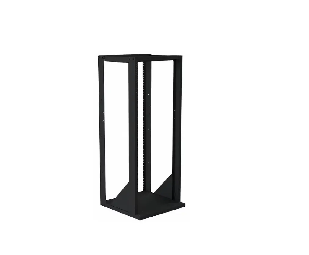
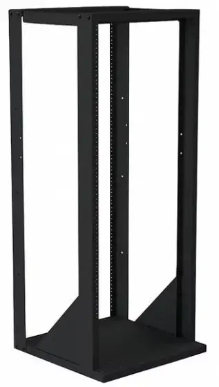
VMP ER-148-4PKIT 2-Post Expansion Kit
PARTS
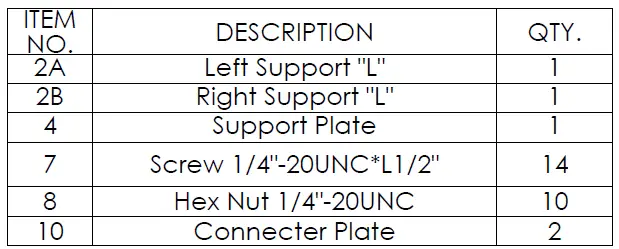
Step 1
Before starting lay out all parts to your mount and match them to the parts list provided. Verify that you have all your parts before attempting to assemble the mount. Also before attempting to assemble the ER-148-4PKIT you should have already assembled the ER-148.
Note: ER-148-4PKIT part numbers are in circles and ER-148 part numbers are in triangles.
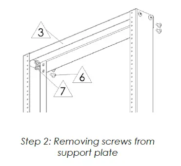
Step 2
Remove the ¼” – 20UNC screws ![]() ER-148 and nuts
ER-148 and nuts![]() ER-148 from the Support Plate
ER-148 from the Support Plate ![]() ER-148.
ER-148.
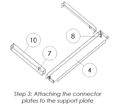
Step 3
Attach the two Connector Plates ![]() ER-148-4PKIT to the Support Plate
ER-148-4PKIT to the Support Plate ![]() ER-148-4PKIT using the ¼” – 20UNC screws
ER-148-4PKIT using the ¼” – 20UNC screws ![]() ER-148-4PKIT and nuts
ER-148-4PKIT and nuts ![]() ER-148-4PKIT.
ER-148-4PKIT.
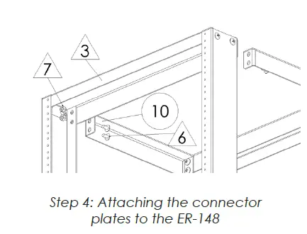
Step 4
Attach the other end of the Connector Plate![]() ER-148-4PKIT to the Support Plate (
ER-148-4PKIT to the Support Plate (![]() ER-148 using the screws (
ER-148 using the screws (![]() ER-148 and nuts (
ER-148 and nuts (![]() ER-148 removed in step 2.
ER-148 removed in step 2.
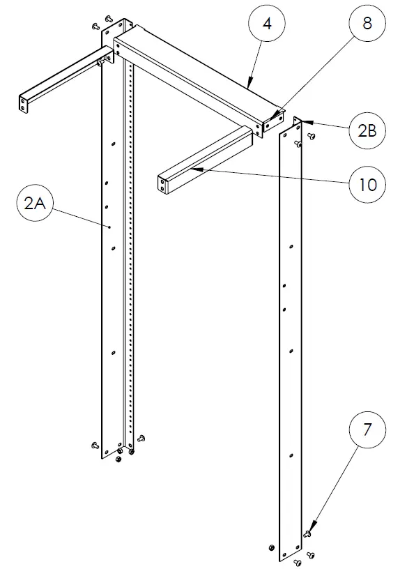
Step 5
Attach the Left Support “L” (![]() ER-148-4PKIT and Right Support “L” (
ER-148-4PKIT and Right Support “L” (![]() ER-148-4PKIT to the Support Plate (
ER-148-4PKIT to the Support Plate (![]() ER-148-4PKIT and Base (
ER-148-4PKIT and Base ( ER-148 using the ¼” -20UNC screws (
![]() ER-148-4PKIT and nuts (
ER-148-4PKIT and nuts (![]() ER-148-4PKIT. Note: It is easier to attach the “L” Supports if you have all the screws lightly secured until all screws are in place and then tighten them down.
ER-148-4PKIT. Note: It is easier to attach the “L” Supports if you have all the screws lightly secured until all screws are in place and then tighten them down.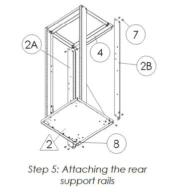
Enjoy Your Mount
WARNING: The installer of these products must verify that the mount surface, ceiling or wall, will safely support the combined weight of all attached equipment and hardware. Video Mount Products will not be held liable for the improper use or installation of its products.
For more information, please contact us at: 345 Log Canoe Circle, Stevensville, Maryland 21666 Toll Free: 877.281.2169 Phone: 410.643.6390 Fax: 410.643.6615 www.videomount.com


