 716 OUTPUT EXPANSION MODULE
Installation Guide
DESCRIPTION
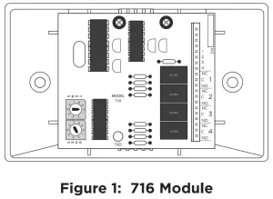
The 716 Output Expansion Module provides four independently programmable Form C (SPDT) relays and four zone‑following annunciator outputs for use on XR150/XR550 Series panels.
Connect the 716 Module to the panel LX‑Bus. The 716 Module cannot be connected to the Keypad Bus.
In addition to the panel onboard Form C relays, you can connect multiple modules to the panel for unique auxiliary relays and annunciator outputs, one per zone. The XR550 has 500 available LX‑Bus zones. The XR150 has 100 available LX‑Bus zones.
Compatibility
- XR150/XR550 Panels
What is Included?
- One 716 Output Expansion Module
- One 20‑Wire Harness
- Hardware Pack
MOUNT THE MODULE
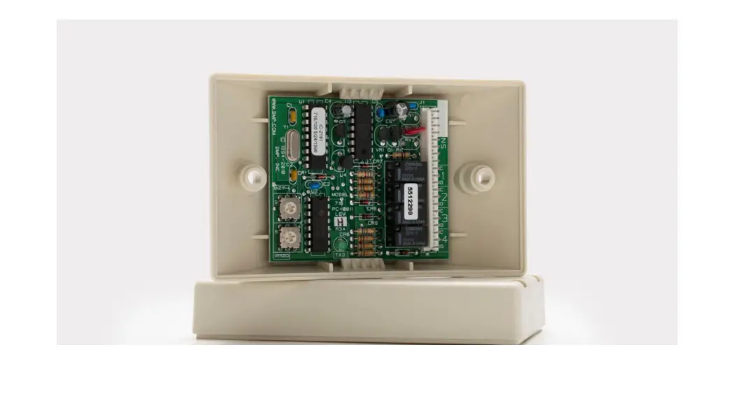
The 716 comes in a high‑impact plastic housing that you can mount directly to a wall, backboard, or another flat surface. For easy installation, the housing base contains holes that allow you to mount the module on a single‑gang switch box or ring. Mount the module outside the panel enclosure.
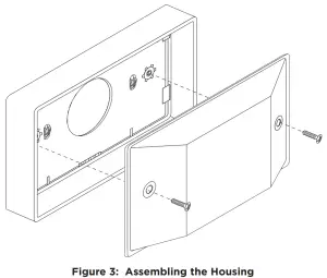
- Remove the housing fastener screws and separate the top housing from the base.
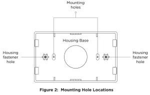
- Insert screws through the desired mounting holes on the housing base. Refer to Figure 2 for mounting hole locations.
- Tighten the screws into place.
- Attach the housing top to the mounting base with the housing fastener screws. Refer to Figure 3.
 |  |
For mounting instructions with a 716T Terminal Strip, see the 716T Terminal Strip Installation Guide LT-2017.
WIRE THE MODULE
Refer to Figure 4 when wiring the module. Connect the included 20‑wire harness to the main header. Connect red, green, and black wires to the panel LX‑Bus. For supervised operation, connect the yellow wire to the panel LX‑Bus. Connect remaining wires as needed. For more information, refer to “Unsupervised Operation” and “Supervised Operation”.
For additional wiring options, see LT-2017 716 Terminal Strip Installation Guide.
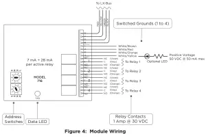
| TERMINAL/WIRE COLOR | PURPOSE |
| R (Red) | Power from Panel (RED) |
| Y (Yellow) | Receive Data from Panel (YEL) |
| G (Green) | Send Data from Panel (GRN) |
| B (Black) | Ground from Panel (BLK) |
| 1 (White/Brown) | Switched Ground 1 |
| 2 (White/Red) | Switched Ground 2 |
| 3 (White/Orange) | Switched Ground 3 |
| 4 (White/Yellow) | Switched Ground 4 |
| NC (Violet) | Relay Output 1 ‑ 4 |
| C (Grey) | Relay Output 1 ‑ 4 |
| NO (Orange) | Relay Output 1 ‑ 4 |
SET THE MODULE ADDRESS
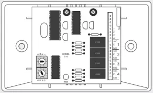
Set the 716 Module to an address that is used by the panel to turn outputs on and off. For easy addressing, the 716 contains two onboard rotary switches that you can set with a small screwdriver.
When using annunciator outputs, set the 716 address to match the zones that you want the outputs to follow.
If you are only using the Form C relays, set the address to match the output numbers that you want to operate.
The module uses two rotary switches (TENS and ONES) to set the module address. Set the switches to match the last two digits of the addresses. For example, for address 02 set the switches to TENS 0 and ONES 2 as shown in Figure 4. For more information, refer to Table 1.![]() Note: Any 711, 714, 714‑8, 714‑16, 714‑8INT, 714‑16INT, 715, or another LX‑Bus device can be set to the same address as a 716 that is operating in unsupervised mode. Sharing an LX‑Bus address in this manner does not cause a conflict between these devices. For more information, refer to “Unsupervised Operation”.
Note: Any 711, 714, 714‑8, 714‑16, 714‑8INT, 714‑16INT, 715, or another LX‑Bus device can be set to the same address as a 716 that is operating in unsupervised mode. Sharing an LX‑Bus address in this manner does not cause a conflict between these devices. For more information, refer to “Unsupervised Operation”.
| SWITCH | XR150 SERIES | XR550 SERIES | |||||
| TENS | ONES | LX500 | LX500 | LX600 | LX700 | LX800 | LX900 |
| 0 | 0 | 500 | 500 | 600 | 700 | 800 | 900 |
| 0 | 1 | 501 | 501 | 601 | 701 | 801 | 901 |
| 0 | 2 | 502 | 502 | 602 | 702 | 802 | 902 |
| 0 | 3 | 503 | 503 | 603 | 703 | 803 | 903 |
| 0 | 4 | 504 | 504 | 604 | 704 | 804 | 904 |
| … | … | … | … | … | … | … | … |
| 9 | 5 | 595 | 595 | 695 | 795 | 895 | 995 |
| 9 | 6 | 596 | 596 | 696 | 796 | 896 | 996 |
| 9 | 7 | 597 | 597 | 697 | 797 | 897 | 997 |
| 9 | 8 | 598 | 598 | 698 | 798 | 898 | 998 |
| 9 | 9 | 599 | 599 | 699 | 799 | 899 | 999 |
Table 1: LX‑Bus and Corresponding Zone Numbers
PROGRAM THE PANEL
Assign the Form C relays to outputs in Output Options and Zone Information, or assign the relays to Zone Alarm Actions. For example, program the panel Telephone Trouble Output to operate output 520 so that trouble on the panel phone line would toggle relay 1 on a module set to address 520. Output 521 would toggle relay 2 on the same 716 modules. The module’s four Form C relays are rated for 1 Amp at 30 VDC resistive. For more information about programming, refer to the appropriate panel programming guide.
ADDITIONAL INFORMATION
Wiring Specifications
DMP recommends using 18 or 22 AWG for all LX‑Bus and Keypad Bus connections. The maximum wire distance between any module and the DMP Keypad Bus or LX‑Bus circuit is 10 feet. To increase the wiring distance, install an auxiliary power supply, such as a DMP Model 505‑12. The maximum voltage drop between a panel or auxiliary power supply and any device is 2.0 VDC. If the voltage at any device is less than the required level, add an auxiliary power supply at the end of the circuit.
To maintain auxiliary power integrity when using 22‑gauge wire on Keypad Bus circuits, do not exceed 500 feet. When using 18‑gauge wire, do not exceed 1,000 feet. The maximum distance for any bus circuit is 2,500 feet regardless of wire gauge. Each 2,500-foot bus circuit supports a maximum of 40 LX‑Bus devices.
For additional information refer to the LX‑Bus/Keypad Bus Wiring Application Note (LT‑2031) and the 710 Bus Splitter/Repeater Module Installation Guide (LT‑0310).
Supervised Operation
To install the module as a supervised device, connect all four LX‑Bus wires from the module to the panel LX‑Bus and program an appropriate zone as a Supervisory (SV) type. The module may use any address for supervision, provided that a Supervisory zone is programmed for that address. For example, zone 504 on an XR550 Series panel would be
programmed as an SV zone to supervise a 716 module set to address 04 on the first LX‑Bus. Only the first zone number for the programmed device is supervised. Refer to Table 1.
When installing Zone Expansion Modules on the same LX‑Bus as a supervised 716 Module, address the Zone Expanders to the next zone number. For example, on an XR550 Series panel, the zone is 520 for supervision and 521 for a zone expander on the same bus.
If a supervised 716 Module loses communication with the panel, an open condition (Trouble) is indicated on its Supervisory zone.
Unsupervised Operation
To operate the module in unsupervised mode, do not connect the yellow wire from the module to the panel LX‑Bus.
The unsupervised operation allows you to install multiple modules and set them to the same address. Do not program a zone address for unsupervised operation. Unsupervised operation is incompatible with fire-listed installations. For more information, refer to “Compliance Listing Specifications”.
Annunciator Outputs (Switch‑to‑Ground)
Unlike the module Form C relays, the four power limited annunciator outputs on the 716 Module follow the zone state having the same address. For example, output 1 (white/brown) on a 716 module set to address 120 shorts to ground each time zone 120 is in alarm or trouble while armed. Use this feature to operate relays or LEDs to show changes in the state of the panel armed zones. Refer to Table 2.
| ARMED ZONE STATE | 716 ANNUNCIATOR OUTPUT ACTION |
| Normal | Off—No ground reference |
| Trouble, wireless low battery, missing | On—Steady short to ground |
| A or “L” in Report to Transmit | Pulse (1.6 seconds On, 1.6 seconds Off) |
| Zone Bypassed | Slow pulse (1.6 seconds On, 4.8 seconds Off) |
Table 2: Annunciator Outputs
Exceptions to Output Expansion Module Addressing
The module can only be wired to an LX‑Bus. To determine the correct output for a particular keypad zone, match the zone number with the annunciator output number. Special addresses are configured to allow the annunciator outputs to follow the panel and keypad zones when connected to the first LX‑Bus. Refer to Table 3.
| LX‑500 ADDRESS | ZONES | LX‑500 ADDRESS | ZONES |
| 501 | 1 to 4 | 581 | 81 to 84 |
| 505 | 5 to 8 | 519 | 91‑94 |
| 509 | 9 to 10 | 529 | 101‑104 |
| 511 | 11 to 14 | 539 | 111‑114 |
| 521 | 21 to 24 | 549 | 121‑124 |
| 531 | 31 to 34 | 559 | 131‑134 |
| 541 | 41 to 44 | 569 | 141‑144 |
| 551 | 51 to 54 | 579 | 151‑154 |
| 561 | 61 to 64 | 589 | 161‑164 |
| 571 | 71 to 74 | ||
Table 3: XR150/XR550 Series LX‑Bus Addresses and Corresponding Zones
COMPLIANCE LISTING SPECIFICATIONS
UL Listed Installations
To comply with ANSI/UL 365 Police‑Connected Burglary System or ANSI/UL 609 Local Burglary Alarm Systems, the module must be mounted in the supplied, UL listed enclosure with a tamper.
Unsupervised operation is not suitable for fire-listed installations.
Any auxiliary power supply for a commercial fire installation must be regulated, power limited, and listed for Fire Protective Signaling.
ULC Commercial Burglary Installations (XR150/XR550 Series Panels)
Place the output module with at least one zone expander in a listed enclosure and connect a DMP Model 307 Clip‑on Tamper Switch to the enclosure programmed as a 24‑hour zone.
716 OUTPUT
EXPANSION MODULE
Specifications
| Operating Voltage | 12 VDC Nominal |
| Operating Current | 7 mA + 28 mA per active relay |
| Weight | 4.8 oz. (136.0 g) |
| Dimensions | 2.5” W x 2.5” H (6.35 cm W x 6.35 cm H) |
Ordering Information
| 716 | Output Expansion Module |
Compatibility
XR150/XR550 Series Panels
716T Terminal Strip
Certifications
California State Fire Marshall (CSFM)
New York City (FDNY COA #6167)
Underwriters Laboratory (UL) Listed
| ANSI/UL 365 | Police Connected Burglar |
| ANSI/UL 464 | Audible Signal Appliances |
| ANSI/UL 609 | Local Burglar |
| ANSI/UL 864 | Fire Protective Signaling |
| ANSI/UL 985 | Household Fire Warning |
| ANSI/UL 1023 | Household Burglar |
| ANSI/UL 1076 | Proprietary Burglar |
| ULC Subject-C1023 | Household Burglar |
| ULC/ORD-C1076 | Proprietary Burglar |
| ULC S304 | Central Station Burglar |
| ULC S545 | Household Fire |
Designed, engineered, and
manufactured in Springfield, MO
using the U.S. and global components.
LT-0183 1.03 20291
© 2020
INTRUSION • FIRE • ACCESS • NETWORKS
2500 North Partnership Boulevard
Springfield, Missouri 65803-8877
800.641.4282
DMP.com


