![]()
LABS WGM110 Wi-Fi Expansion Kit
User Guide
WGM110 Wi-Fi Expansion Kit
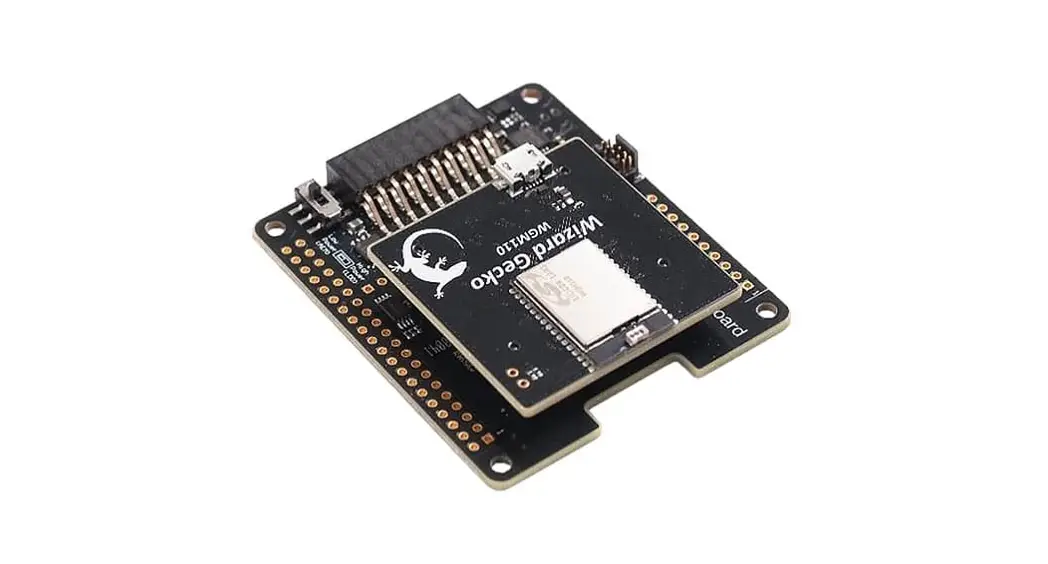
The WGM110 Wi-Fi Expansion Kit is an excellent way to explore and evaluate the WGM110 Wi-Fi Module with an EFM32 MCU for your embedded application.
The kit contains a Wireless Expansion Board (BRD8016A) and a WGM110 Wi-Fi Module Radio Board
The kit contains a Wireless Expansion Board (BRD8016A) and a WGM110 Wi-Fi Mod-ule Radio Board (BRD4320A). The WGM110 Wi-Fi Module is an easy to use and easy to interface Wi-Fi Network Co-Processor (NCP). Most of the associated complexity of Wi-Fi and the protocol stack is offloaded to the module and allows for easy Wi-Fi inte-gration into any embedded system.
The kit easily integrates and brings Wi-Fi connectivity to a compatible Silicon Labs MCU Starter Kit through the expansion header. The Wireless Expansion Board has al-so been designed after the Raspberry Pi Hardware Attached on Top (HAT) board speci-fication, allowing the WGM110 Wi-Fi Expansion Kit to connect to a Raspberry Pi. 
WIRELESS EXPANSION BOARD FEATURES
- EXP connector for interfacing Silicon Labs Starter Kits
- Common feature set, including SPI, UART, and I2C
- Allows board detection and identification
- Radio Board connectors for inserting Silicon Labs Wireless Radio Boards
- Mini Simplicity debug connector
- Supports programming and debugging the module firmware
- LDO for high-power radio boards
- Raspberry Pi compatible HAT
- Unpopulated header
- HAT EEPROM for identification
WGM110 WI-FI MODULE RADIO BOARD FEATURES
- WGM110A Wizard Gecko Wi-Fi Module
- Integrated chip antenna
- 802.11b/g/n compliant
- TX power: 16 dBm
- RX sensitivity: -98 dBm
- CPU core: 32-bit ARM® Cortex-M3
- Flash memory: 1 MB
- RAM: 128 kB
- Module certification: FCC, IC, Japan and Korea
- CE compliant
Introduction
The WGM110 Wi-Fi Expansion Kit (OPN: SLEXP4320A) contains a Wireless Expansion Board (BRD8016A) and a WGM110 Wi-Fi Module Radio Board (BRD4320A) that plug directly into each other. The core of the kit is a WGM110 Wizard Gecko Wi-Fi Module which makes this kit an excellent starting point for adding Wi-Fi connectivity to a compatible Silicon Labs MCU Starter Kit.
The kit connects and works out-of-the box by inserting it into the expansion header of one of these Silicon Labs MCU Starter Kits (STKs):
- EFM32 Pearl Gecko PG12 Starter Kit – SLSTK3402A
- EFM32 Pearl Gecko PG1 Starter Kit – SLSTK3401A
- EFM32 Giant Gecko GG11 Starter Kit – SLSTK3701A
Note: The kit is sold without a Silicon Labs MCU STK.
The firmware and demo that is available with the kit targets applications where the MCU on the STK serves as a host that drives the application and tells the WGM110 Wi-Fi Module what to do. The picture below shows the kit connected to a Silicon Labs MCU STK through the Expansion Header.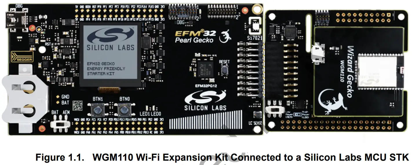 Although the main connectivity path for the kit is to a Silicon Labs MCU STK through the Expansion Header, the kit can also connect to a Raspberry Pi and function as a Raspberry Pi HAT. To do so, a dual row, female socket, 0.1″ pitch connector must be soldered in.
Note: Do not connect the kit to both a Silicon Labs MCU STK and a Raspberry Pi at the same time.
Kit Contents
The following items are included in the box:
- 1x Wireless Expansion Board (BRD8016A)
- 1x WGM110 Wi-Fi Module (BRD4320A)
Getting Started
Detailed instructions for how to get started can be found on the Silicon Labs web pages:
http://www.silabs.com/start-efm32-wifi
Hardware Overview
Hardware Layout
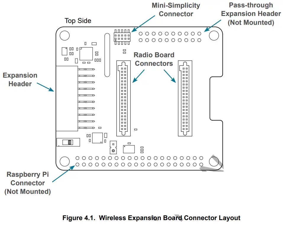
The layout of the WGM110 Wi-Fi Expansion Kit is shown in the figure below.
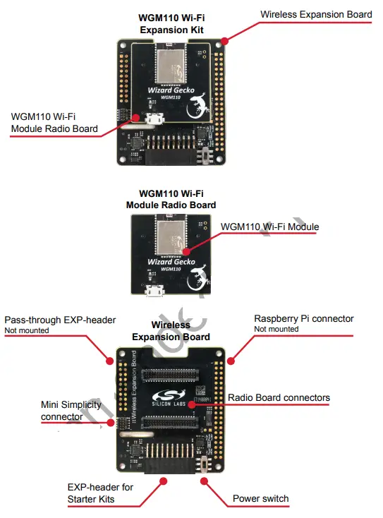 Figure 2.1. WGM110 Wi-Fi Expansion Kit Hardware Layout
Wi-Fi Expansion Kit
The Wizard Gecko WGM110 is an all-inclusive Wi-Fi Module targeted for applications where good RF performance, low power consumption, and easy application development, together with fast time to market, are key requirements. WGM110 has excellent RF performance and can provide long range with robust wireless connectivity. The WGM110 Module integrates all of the necessary elements required for an IoT Wi-Fi application, including an 802.11b/g/n radio, integrated chip antenna, certifications, a microcontroller, Wi-Fi and IP stacks, an HTTP server, and multiple protocols, such as TCP and UDP.
WGM110 can act as a Wi-Fi client or be used as a Wi-Fi access point, making the provisioning of the device as easy as surfing on the web. WGM110 can host BGScript end user applications, which means applications can be designed without relying on an external microcontroller. Alternatively, the Wi-Fi Module can run in Network Co-Processor (NCP) mode, leaving the complexity of TCP/IP networking to the Module so that the customer’s own host controller can be fully dedicated to processing the customer application tasks.
The Wi-Fi expansion kit provides the ability to pair up the WGM110 Wi-Fi Module with an EFM32 host running the user application, using the module as a network co-processor. The kit provides the Wireless EXP Board and a WGM110 Wi-Fi Module Radio Board, and should be used together with a Silicon Labs MCU Starter Kit, such as the EFM32 Pearl Gecko PG12 STK. NCP mode of operation is the primary focus of this kit. For standalone application development, the Wizard Gecko Wi-Fi Module Wireless Starter Kit (SLWSTK6120A) is recommended instead.
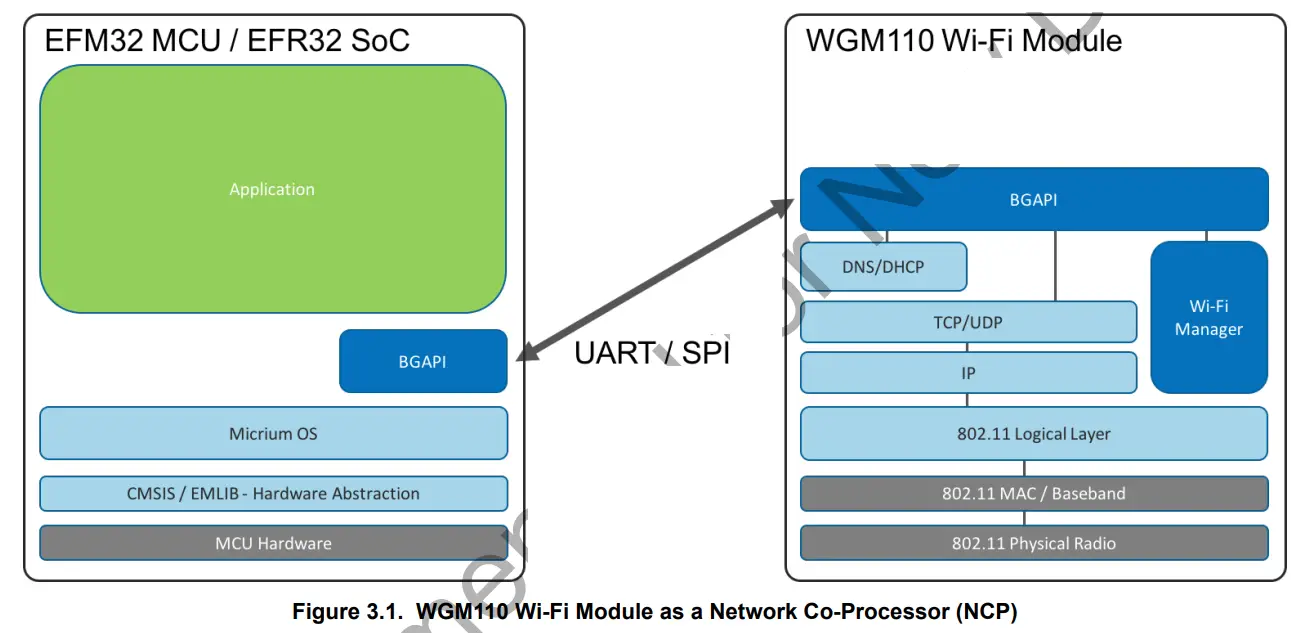
The WGM110 Wi-Fi Module in the kit is pre-configured as a network co-processor, requiring no additional programming of the module itself in order to be used with an MCU Starter Kit. Wi-Fi functionality is exposed to the host MCU on the Starter Kit through the BGAPI interface, over a UART or SPI interface. (UART with RTS/CTS flow control is enabled by default).
All Wi-Fi and network actions are performed through this interface, and the user can focus on developing the application on the host MCU. The module application programming interface is described in detail in the WGM110 API Reference Manual.
Board Setup
- Insert the WGM110 Wi-Fi Module Radio Board into the radio board connectors on the Wireless EXP board.
- Plug the Wireless EXP Board into the EXP header of the MCU Starter Kit.
- Place the MCU power switch in the “AEM” position, and the Wireless EXP Board power switch in the “High Power (LDO)” position.
- Insert the USB cable to power up the kit and connect it to a computer.
A detailed quick start guide is described in QSG145: WGM110 SLEXP4320 Wi-Fi Expansion Kit Quick-Start Guide.
Board Identification
The Starter Kit and Wireless EXP board provide identification of all the connected boards. This detection and identification is used by the Simplicity Studio tool to present the correct documentation and software examples.
The kit is able to detect which radio board is inserted, but requires the board to be inserted at power-on. It is therefore important to always connect the boards together before inserting the USB cable into the starter kit (powering on the boards).
Host Interfaces
There are two available host interfaces on the WGM110 Wi-Fi Expansion Kit, one of which can be used to connect the WGM110 Wi-Fi Module to an external host. The production firmware on the WGM110 Wi-Fi Module uses UART with RTS/CTS flow control as the default host interface. For information on how to reprogram the firmware on the WGM110 Wi-Fi Module, see Section 5. Reconfiguring the Wi-Fi Module Firmware.
UART
UART with RTS/CTS flow control is enabled by default on the production firmware of the WGM110 Wi-Fi Module. The UART peripheral routing is illustrated in the figure below. 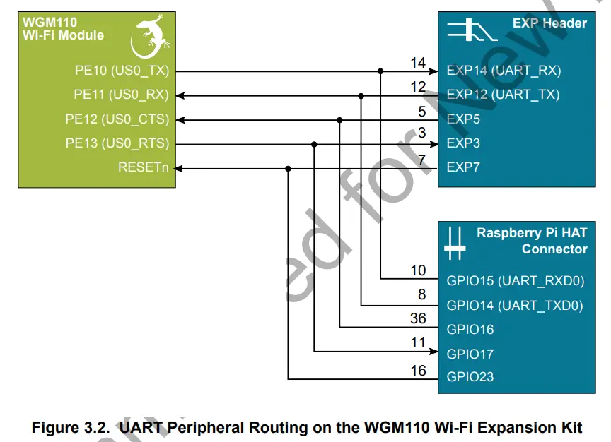 The table below shows the features of the UART host interface. The WGM110 Wi-Fi Module comes programmed with the settings listed under default value.
Table 3.1. UART Host Interface Features and Default Values
| Parameter | Features Supporte Ranges | Defacth 2 VakcG |
| UART baud rate | 9600 bps – 6 Mbps | 115200 Kbps |
| Flow control | RTS/CTS | Enabled |
| Data bits | 8 or 9 | 8 |
| Parity | none, odd, even | None |
| Stop bits | 1 or 2 | 1 |
| Host protocol | BGAPI serial protocol | BGAPI serial protocol |
SPI
SPI is one of two host interfaces available on the Wireless Expansion Board. In order to use SPI as the connection between the WGM110 Wi-Fi Module and a host, the module must be reprogrammed. For more information about how to do this, see Section 3. WiFi Expansion Kit. The SPI peripheral routing is illustrated in the figure below. 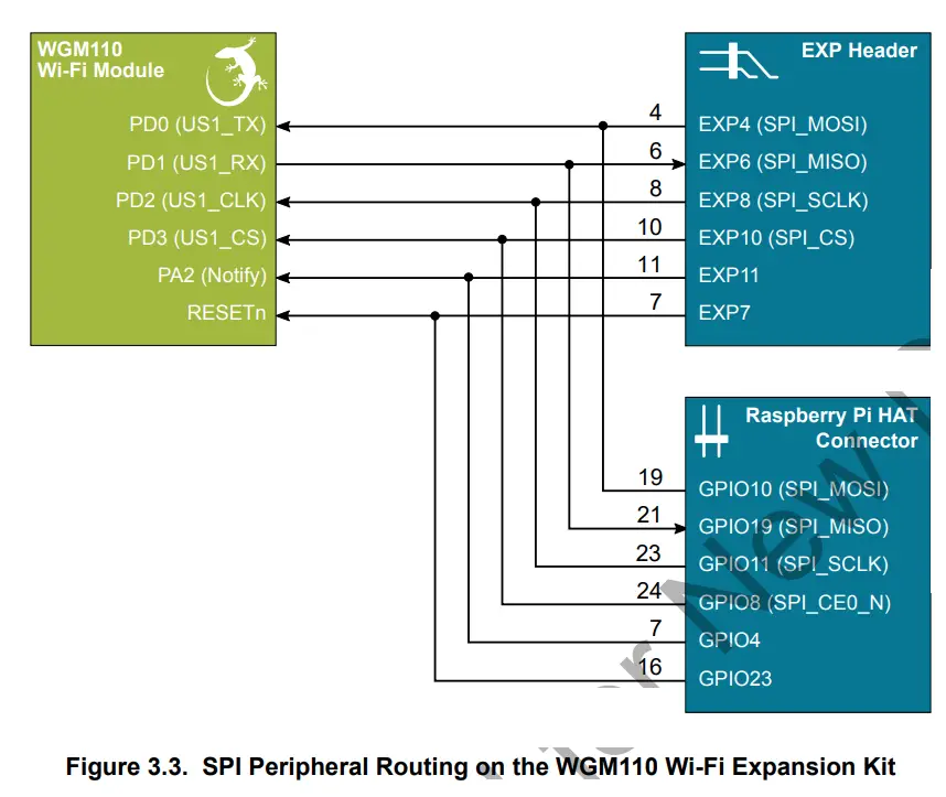
The table below shows the features of the SPI host interface.
Table 3.2. SPI Host Interface Features
| Parameter | Features (Value Ranges) |
| SPI mode | SPI slave |
| Bit rates | 9600 bps – 6 Mbps |
| Bit order | MSB first |
| Clock polarity and phase | Configurable |
| Host protocol | BGAPI serial protocol |
STK Pin Mapping
The pins connected to the WGM110 Wi-Fi Module will vary based on which Starter Kit is used in the configuration. The software running on the MCU Starter Kit needs to take this into account. The table below shows the pin connections when using either the EFM32 Pearl Gecko PG1 STK or the EFM32 Pearl Gecko PG12 STK.
Table 3.3. MCU Pin Mapping
| EXP Header Pin | Module Function | EFM32 Pearl Gecko PG1 STK | EFM32 Pearl Gecko PG12 STK |
| EXP4 | SPI_MOSI | PC6 (US1_TX#11) | PA6 (US2_TX #1) |
| EXP6 | SPI_MISO | PC7 (US1_RX #11) | PA7 (US2_RX #1) |
| EXP8 | SPI_SCLK | PC8 (US1_CLK #11) | PA8 (US2_CLK #1) |
| EXP10 | SPI_CS | PC9 (US1_CS #11) | PA9 (US2_CS #1) |
| EXP12 | UART_RXD | PA0 (US0_TX #0) | PD10 (US0_TX #18) |
| EXP14 | UART_TXD | PA1 (US0_RX #0) | PD11 (US0_RX #18) |
| EXP3 | UART_RTS | PA2 (US0_CTS #31) | PC9 (US0_CTS #10) |
| EXP5 | UART_CTS | PA3 (US0_RTS #31) | PD9 (US0_RTS #12) |
| EXP7 | RESET | PA4 | PB6 |
Note that the peripheral mapping shown in the right column is just an example. The flexibility of the EFM32 devices allow a number of different peripherals to be mapped to these pins. The important thing to note is which pin is used for the connection. The peripheral usage is a design choice that depends on which other resources are required by the application.
Wireless EXP Board
This chapter gives an overview of the Wireless Expansion Board connectivity and power connections.
 EXP Header
 EXP Header
On the left hand side of the Wireless Expansion Board, an angled female 20-pin expansion header is provided to allow connection to one of Silicon Labs’ supported Starter Kits. The expansion header on the Starter Kits follows a standard which ensures that commonly used peripherals such as an SPI, a UART, and an I2C bus, are available on fixed locations on the connector. Additionally, the VMCU, 3V3 and 5V power rails are also available on the expansion header. For detailed information regarding the pinout to the expansion header on a specific Starter Kit, consult the accompanying user’s guide.
The figure below shows how the WGM110 Wi-Fi Module is connected to the connector and the peripheral functions that are available.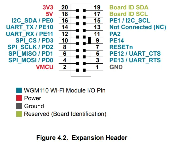
Pass-through Expansion Header
The Wireless Expansion Board features a footprint for a secondary expansion header. The signals from the expansion header are directly tied to the corresponding pins in the footprint, allowing daisy-chaining of additional expansion boards if a connector is soldered in.
Expansion Header Pinout
The table below shows the pin assignments of the Expansion Header, and the port pins and peripheral functions that are available on the WGM110 Wi-Fi Module.
Table 4.1. Expansion Header Pinout
| Expansion Header | WGM110 Wi-Fi Module | Raspberry Pi Con. | Mini Simplicity Con. | ||
| Pin | Function | Pin | Peripheral | Pin(s) | Pin |
| 2 | WGM110 Wi-Fi Module voltage domain (power switch set to Low Power) | VMCU | – | ||
| 4 | SPI_MOSI | PDO | USART1_MOSI | 19, 33 | – |
| 6 | SPI_MISO | PD1 | USART1_MISO | 21 | – |
| 8 | SPI_SCLK | PD2 | USART1_CLK | 23, 38 | |
| 10 | SPI_CS | PD3 | USART1_CS | 24 | – |
| 12 | UART_TX | PE11 | USARTO_RX | 8 | 4 |
| 14 | UART_ RX | PE10 | USARTO_TX | 10 | 5 |
| 16 | 12C_SDA | PEO | 2C1_SDA | 3 | – |
| 18 | Board 5V supply. Used to supply LDO regulator. | 5V | 2, 4 | – | |
| 20 | Board 3V3 supply. Only used for board identification. | 3V3 | 1, 17 | – | |
| 1 | Ground | GND | 6, 9, 14, 20, 25, 30, 34, 39 | 2 | |
| 3 | UART_CTS | PE13 | USARTO_RTS | 11,40 | – |
| 5 | UART_RTS | PE12 | USARTO_CTS | 37, 36 | – |
| 7 | Reset | RESE Tn | 16 | 3 | |
| 9 | GPIO | PE14 | 15 | – | |
| 11 | GPIO | PA2 | 7 | – | |
| 13 | Not Connected | – | – | ||
| 15 | I2C_SCL | PE1 | 12C1_SCL | 5 | – |
| 17 | Identification of expansion boards | BOARD_ID_SC L | – | – | |
| 19 | Identification of expansion boards | BOARD_ID_SD A | – | – | |
Raspberry Pi Connector
On the bottom side of the Wireless Expansion Board, a dual row, female socket, 0.1″ pitch connector can be soldered in to allow the WGM110 Wi-Fi Expansion Kit to act as a Raspberry Pi Hardware Attached on Top (HAT) board.
The figure below shows how the WGM110 Wi-Fi Module is connected to the connector and the peripheral functions that are available.
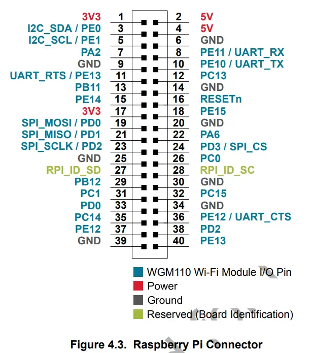
Raspberry Pi Connector Pinout
The table below shows the pin assignments of the Raspberry Pi connector, and the port pins and peripheral functions that are available on the WGM110 Wi-Fi Module.
Table 4.2. Raspberry Pi Connector Pinout
| Raspberry Pi Connector | Expansion Header | Mini Simplicity Con. | |||
| Pin(s) | WGM110 Pin | Function | Raspberry Pi Pin | Pin | Pin |
| 1 | 3V3 | Board 3V3 supply | 3v3 Power | 20 | – |
| 2 | 5V | Board 5V supply | 5v Power | 18 | – |
| 3 | PE0 | I2C_SDA | BCM 2 (SDA) | 16 | – |
| 4 | 5V | Board 5V supply | 5v Power | 18 | – |
| 5 | PE1 | I2C_SCL | BCM 3 (SCL) | 15 | – |
| 6 | GND | Ground | Ground | 1 | 2 |
| 7 | PA2 | GPIO | BCM 4 (GPCLK0) | 11 | – |
| 8 | PE11 | UART_RX | BCM 14 (TXD) | 12 | 4 |
| 9 | GND | Ground | GND | 1 | 2 |
| 10 | PE10 | UART_TX | BCM 15 (RXD) | 14 | 5 |
| 11 (40) | PE13 | UART_RTS | BCM 17 | 3 | – |
| 12 | PC13 | GPIO | BCM 18 (PWM0) | – | – |
| 13 | PB11 | GPIO | BCM 27 | – | – |
| 14 | GND | Ground | Ground | 1 | 2 |
| 15 | PE14 | GPIO | BCM 22 | 9 | – |
| 16 | RESETn | Reset | BCM 23 | 7 | 3 |
| 17 | 3V3 | Board 3V3 supply | 3v3 Power | 20 | – |
| 18 | PE15 | GPIO | BCM 24 | – | – |
| 19 (33) | PD0 | SPI_MOSI | BCM 10 (MOSI) | 4 | – |
| 20 | GND | Ground | Ground | 1 | 2 |
| 21 | PD1 | SPI_MISO | BCM 9 (MISO) | 6 | – |
| 22 | PA6 | GPIO | BCM 25 | – | – |
| 23 (38) | PD2 | SPI_SCLK | BCM 11 (SCLK) | 8 | – |
| 24 | PD3 | SPI_CS | BCM 8 (CE0) | 10 | – |
| 25 | GND | Ground | Ground | 1 | 2 |
| 26 | PC0 | GPIO | BCM 7 (CE1) | – | – |
| 27 | ID_SD | ID EEPROM | BCM 0 (ID_SD) | – | – |
| 28 | ID_SC | ID EEPROM | BCM 1 (ID_SC) | – | – |
| 29 | PB12 | GPIO | BCM 5 | – | – |
| 30 | GND | Ground | Ground | 1 | 2 |
| 31 | PC1 | GPIO | BCM 6 | – | – |
| 32 | PC15 | GPIO | BCM 12 (PWM0) | – | – |
| 33 (19) | PD0 | GPIO | BCM 13 (PWM1) | 4 | – |
| 34 | GND | Ground | Ground | 1 | 2 |
| 35 | PC14 | GPIO | BCM 19 (MISO) | – | – |
| 36 (37) | PE12 | UART_CTS | BCM 16 | 5 | – |
| 37 (36) | PE12 | GPIO | BCM 26 | 5 | – |
| 38 (23) | PD2 | GPIO | BCM 20 (MOSI) | 8 | – |
| 39 | GND | Ground | Ground | 1 | 2 |
| 40 (11) | PE13 | GPIO | BCM 21 (SCLK) | 3 | – |
Note: Several of the Raspberry Pi GPIO pins are connected together when the WGM110 Wi-Fi Module Radio Board is inserted. This is because of connections on the radio board itself, and are not because they are connected together on the Wireless EXP Board. Care must be taken when driving these pins to avoid creating short circuits.
Mini Simplicity Connector
The Mini Simplicity connector, featured on the WGM110 Wi-Fi Expansion Kit, allows the use of an external debugger, such as those featured on one of the kits listed under Section 1. Introduction. In addition to providing serial wire debug (SWD) and virtual COM port functionality, the debugger on the STKs can also support advanced energy profiling tools. For more information see AN958: Debugging and Programming Interfaces for Custom Designs.
Note: Using the Mini Simplicity connector with the kit requires a Silicon Labs debug adapter kit (OPN: SLSDA001A).
The pinout of the connector, as seen from the WGM110 Wi-Fi Module side, is illustrated in the figure below.
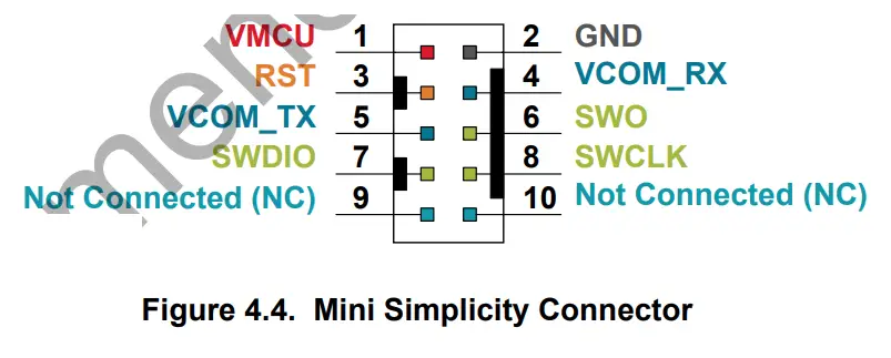 Mini Simplicity Connector Pinout
The pin assignment of the Mini Simplicity connector on the board is given in the table below.
Table 4.3. Mini Simplicity Connector Pin Descriptions
| Pin Number | WGM110 Connection | Function | Description |
| 1 | VMCU | VAEM | Target voltage on the debugged application. Supplied and monitored by the AEM when the power selection switch on the STK used for debugging is in the “AEM” position. |
| 2 | GND | GND | Ground |
| 3 | Reset | DBG_RST | Reset |
| 4 | PE11 | VCOM_RX | Virtual COM Rx |
| 5 | PE10 | VCOM_TX | Virtual COM Tx |
| 6 | PF2 | DBG_SWO | Serial Wire Output |
| 7 | PF1 | DBG_SWDIO | Serial Wire Data |
| 8 | PF0 | DBG_SWCLK | Serial Wire Clock |
| 9 | NC | Not connected | – |
| 10 | NC | Not connected | – |
Power Supply
There are three ways to provide power to the kit:
- The kit can be connected to, and powered by, a Silicon Labs MCU STK
- The kit can be connected to, and powered by, a Raspberry Pi
- If the kit is connected to a Silicon Labs MCU STK, the kit can also be powered through the Mini Simplicity Connector.
Note: Connecting the WGM110 Wi-Fi Expansion Kit to both an STK and a Raspberry Pi at the same time is not a valid option.
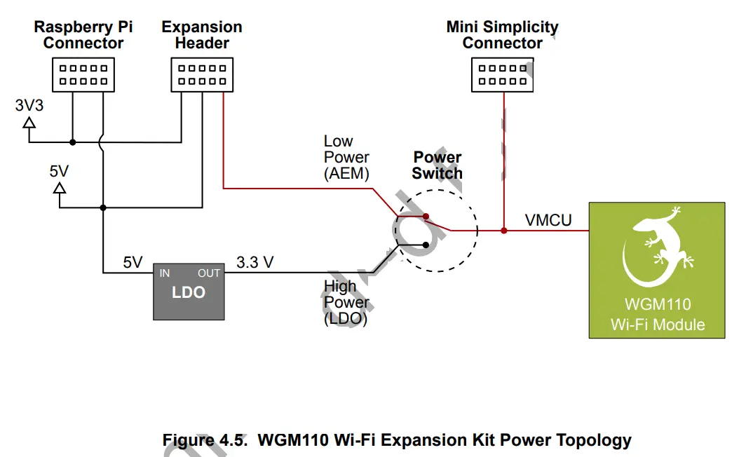
When connected to a Silicon Labs MCU STK, the WGM110 Wi-Fi Module can either be powered by the VMCU rail present on the Expansion Header, or through an LDO regulator on board the Wireless Expansion Board. The LDO regulator draws power from the 5V net, and hence, the power consumption of the WGM110 Wi-Fi Module will not be included in any AEM measurements performed by the MCU STK. A mechanical power switch on the Wireless Expansion Board is used to select between Low Power (AEM) mode and High Power (LDO) mode. When the switch is set to Low Power (AEM) mode, the WGM110 Wi-Fi Module is connected to the VMCU net on the Expansion Header. When the switch is set to High Power (LDO) mode, the WGM110 Wi-Fi Module is connected to the output of the LDO. For applications requiring high power consumption, or when the WGM110 Wi-Fi Expansion Kit is connected to a Raspberry Pi, the power switch must be set to High Power (LDO) mode.
The power topology is illustrated in the figure below.
The power supply options are summarized in Table 4.4 WGM110 Wi-Fi Expansion Kit Power Options on page 15. Information on placement of the power switch and the connectors can be found in Section 2.1 Hardware Layout.
Table 4.4. WGM110 Wi-Fi Expansion Kit Power Option
| Host | Host MCU STK Power Switch | Debugger (STK) Power Switch | Wireless Expansion Board Power Switch | Power Source |
| MCU STK | AEM | BAT | Low power (AEM) | MCU STK provides power to both MCU and radio board. |
| MCU STK | AEM | BAT | High power (LDO) | MCU is powered by MCU STK. Radio board is powered by LDO on the Wireless Expansion Board |
| MCU STK | BAT | AEM | Low power (AEM) | External STK debugger provides power to both MCU and radio board. |
| Raspberry Pi | – | BAT | High power (LDO) | Radio board is powered by LDO on the Wireless Expansion Board |
Note: It is important to only use the configurations provided in the table above in order to avoid any power conflicts. Furthermore, it is important to make sure that the coin cell battery holder is empty whenever the power switch should be set to BAT.
Reconfiguring the Wi-Fi Module Firmware
The WGM110 Wi-Fi Module has several hardware interfaces that can be enabled, including the SPI slave interface, the USB device, and the micro-SD card. To configure the module’s hardware interfaces, the module firmware needs to be recompiled and re-programmed.
The Mini Simplicity connector on the Wireless EXP Board provides a Serial Wire Debug interface to the WGM110 module, which can be used to upload the reconfigured module firmware. Alternatively, the Device Firmware Update protocol (DFU) can be used to update the firmware over the UART or SPI interface.
Building the Module Firmware
Configuring the hardware interface settings of the WGM110 can be done using either the BGBuild command line tool, or the GUI based BGTool. UG161: WGM110 Wi-Fi Module Configuration Guide explains in detail how to configure the hardware interfaces of the WGM110 Wi-Fi Module.
Programming the Module Firmware
The 10-pin Mini Simplicity connector on the Wireless EXP Board provides a Serial Wire Debug connection to the WGM110 Wi-Fi Module that can be used to upload the re-configured module firmware. Silicon Labs offers a Simplicity Debug Adapter Board that connects between the two 20-pin debug connectors on Silicon Labs Starter Kits and the 10-pin connector on the Wireless EXP Board.
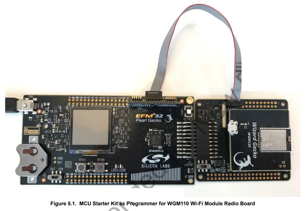
When programming the module firmware using the BGTool, the Starter Kit’s debug multiplexer must be set to “Debug OUT”. This allows the kit to program the module connected through the debug adapter instead of the on-board MCU. The Simplicity Studio tool provides a device configuration utility that can change the kit’s debug mode between “MCU” and “OUT”.
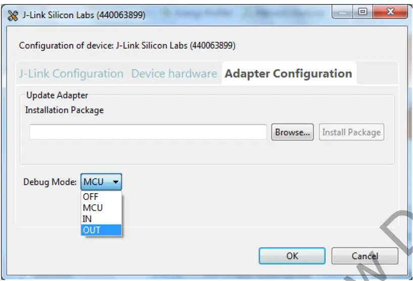 Figure 5.2. Configuring the Debug Mode
Remember to change the debug mode back to MCU after the module has been configured in order to continue application development on the host MCU.
Schematics, Assembly Drawings, and BOM
Schematics, assembly drawings, and bill of materials (BOM) are available through Simplicity Studio when the kit documentation package has been installed.
Kit Revision History
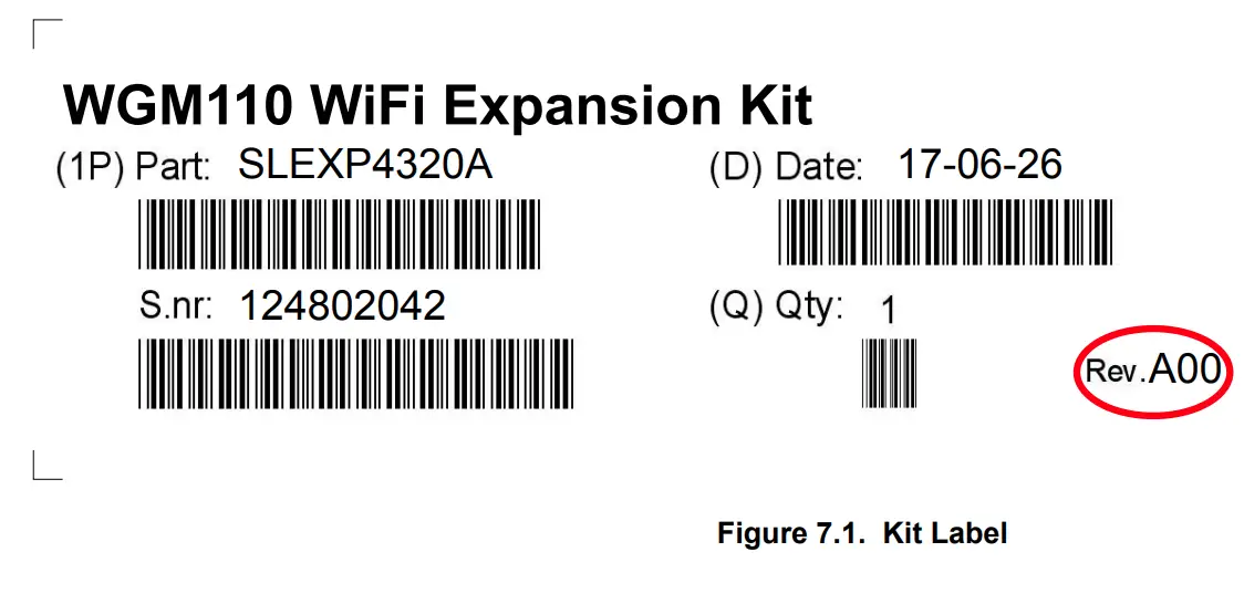
The kit revision can be found printed on the kit packaging label, as outlined in the figure below.
SLEXP4320A Revision History
| Kit Revision | Released | Description |
| A00 | 2017-06-26 | Initial release. |
Document Revision History
Revision 1.0
2017-06-12
- Initial document revision.

Simplicity Studio
One-click access to MCU and wireless tools, documentation, software, source code libraries & more. Available for Windows,
Mac and Linux!
| IoT Portfolio www.silabs.com/IoT | SW/HW www.silabs.com/simplicity | Quality www.silabs.com/quality | Support and Community community.silabs.com |
Disclaimer
Silicon Labs intends to provide customers with the latest, accurate, and in-depth documentation of all peripherals and modules available for system and software implementers using or intending to use the Silicon Labs products. Characterization data, available modules and peripherals, memory sizes and memory addresses refer to each specific device, and “Typical” parameters provided can and do vary in different applications. Application examples described herein are for illustrative purposes only. Silicon Labs reserves the right to make changes without further notice and limitation to product information, specifications, and descriptions herein, and does not give warranties as to the accuracy or completeness of the included information. Silicon Labs shall have no liability for the consequences of use of the information supplied herein. This document does not imply or express copyright licenses granted hereunder to design or fabricate any integrated circuits. The products are not designed or authorized to be used within any Life Support System without the specific written consent of Silicon Labs. A “Life Support System” is any product or system intended to support or sustain life and/or health, which, if it fails, can be reasonably expected to result in significant personal injury or death. Silicon Labs products are not designed or authorized for military applications. Silicon Labs products shall under no circumstances be used in weapons of mass destruction including (but not limited to) nuclear, biological or chemical weapons, or missiles capable of delivering such weapons.
Trademark Information
Silicon Laboratories Inc.® , Silicon Laboratories®, Silicon Labs®, SiLabs® and the Silicon Labs logo®, Bluegiga®, Bluegiga Logo®, Clockbuilder®, CMEMS®, DSPLL®, EFM®, EFM32®, EFR, Ember®, Energy Micro, Energy Micro logo and combinations thereof, “the world’s most energy friendly microcontrollers”, Ember®, EZLink®, EZRadio®, EZRadioPRO®, Gecko®, ISOmodem®, Micrium, Precision32®, ProSLIC®, Simplicity Studio®, SiPHY®, Telegesis, the Telegesis Logo®, USBXpress®, Zentri and others are trademarks or registered trademarks of Silicon Labs. ARM, CORTEX, Cortex-M3 and THUMB are trademarks or registered trademarks of ARM Holdings. Keil is a registered trademark of ARM Limited. All other products or brand names mentioned herein are trademarks of their respective holders.
![]()
Silicon Laboratories Inc.
400 West Cesar Chavez
Austin, TX 78701
USA
http://www.silabs.com


