JAMECO P7100 1X/10X Oscilloscope Passive Probe
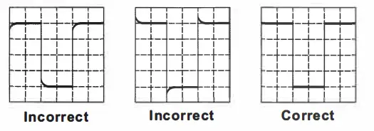
Frequency Compensation
Before taking any measurements using a probe, first check the compensation of the probe and adjust it to match the channel inputs. Most oscilloscopes have a square wave reference signal available at a terminal on the front panel used to compensate the probe. Connect the probe to the signal source on your oscilloscope.
Set the probe to 1 OX position. Adjust trimmer until seeing flat-top square wave on the display.
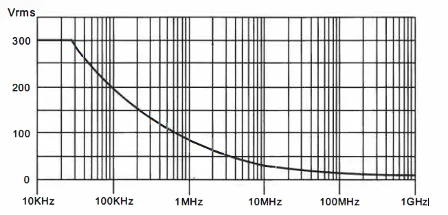
Voltage vs Frequency Rating Curve(RMS)
- CATII 11:c measurement category II is for measurements performed on circuits directly connected to low voltage installations. Examples are
measurements on household appliances, portable tools and similar equipment. - Equipment fully protected by DOUBLE INSULATTION or REINFORCED INSULATION.
- Review this user manual carefully to avoid any personal injury or damage to this product and any product connected to it. To avoid potential hazards, use this product only as specified.
- The measurement category of a combination of a PROBE ASSEMBLY and an accessory (an auxiliary to the measurement) is the lower of the measurement categories of the PROBE ASSEMBLY and of the accessory.
- Follow the instructions to use the PROBE ASSEMBLY will impair or ruin its self-owned protection function.
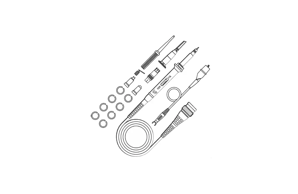
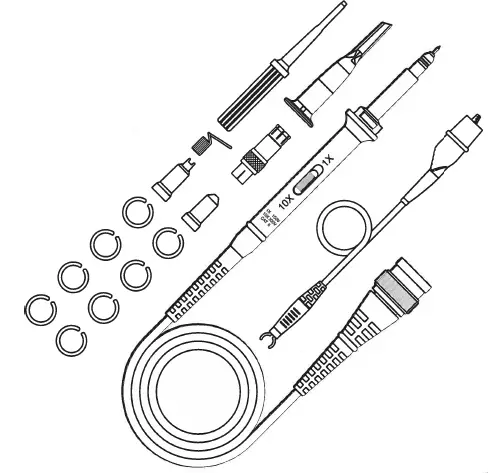
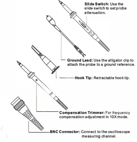
Accessories and Features
Probe is provided with several accessories designed to make probing and measurement simpler. Please take a moment to familiarize yourself with these accessories and their uses.

Probe Characteristics
| Probe Characteristics | |
| Model | P7100 P7200 P7300 |
| Attenuation Ratio | 1X&10X |
| Bandwidth | 100MHz 200MHz 300MHz |
| Rise time | 3.5ns 1.75ns 1.15ns |
| Input Resistance | 1MO/10MO±2% |
| Input Capacitance | 1X:85pF~ 120pF |
| 10X:18.5pF~22.5pF | |
| Max. Input Voltage | 1X:150V RMS CAT II&10X:300V RMS CAT II |
| Compensation Range | 10pF-35pF 8pF~25pF |
| Operation Temperature | -1o”C-+ss·c |
| Humidity | -40°C or below ..;go% +41·c to +50″C ..;so% |
| Altitude | Operating 3000m Nonoperating 15000m |
| Cable Length | 130±2cm |
| Weight | About55g |
| Safety | IEC61010-031 |
Accessory Kit
| Accessory Kit | ||
| Item | Description | Quantity |
| 1 | Retractable Hook Tip | 1 |
| 2 | Adjustment Tool | 1 |
| 3 | Locating Sleeve | 2 |
| 4 | Marker Rings | 8 |
| 5 | Ground L ad | 1 |
| 6 | Ground Spring(Above 100MHz) | 1 |
| 7 | BNC Adapter(Above 200MHz) | 1 |
Note:
content of this document are subject to change without notice.


