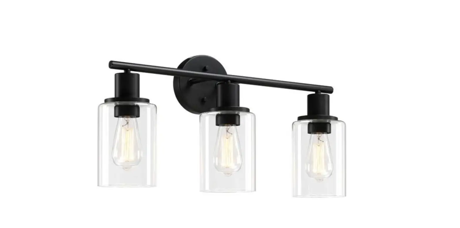
Pia Ricco 1JAY-81963 23.64 Inch 3 Light Bronze Transitional Bathroom Vanity Light Instruction Manual
ASSEMBLY INSTRUCTIONS
![]() CAUTION
CAUTION
- Inspect the wire insulation for any cuts, abrasions, or exposed copper that may have resulted during shipping. If there is a defect in the wire, do not attempt installation.
- Before starting installation of this fixture or removal of a previous fixture, disconnect the power by turning off the circuit breaker or by removing the fuse at the fuse box.
TOOLS REQUIRED
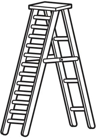
- Ladder
- Safety glasses

- Electrical tape

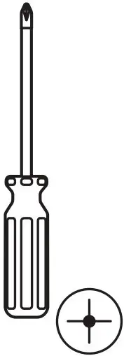
- Phillips screwdriver
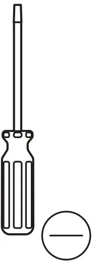
- Flat blade screwdriver
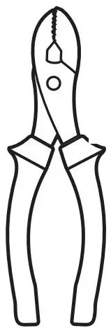
- Pliers
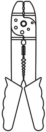
- Wire strippers
HARDWARE INCLUDED
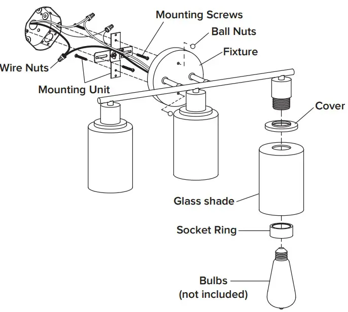
- Fixture
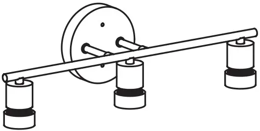
- Cover
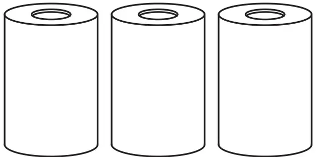
- Glass shade
- Mounting Unit
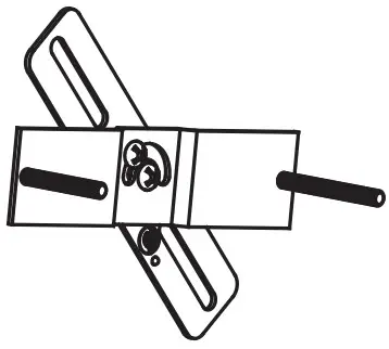
- Ball Nuts

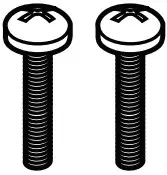
- Mounting Screws
- Wire Nuts

*PARTS SHOWN MAY DIFFER SLIGHTLY PER LIGHT FIXTUR
EXPLODED PARTS
Installation
STEP 1
Unscrew the ball nuts from the mounting unit. Use the mounting screws to attach the mounting unit to the junction box(not included).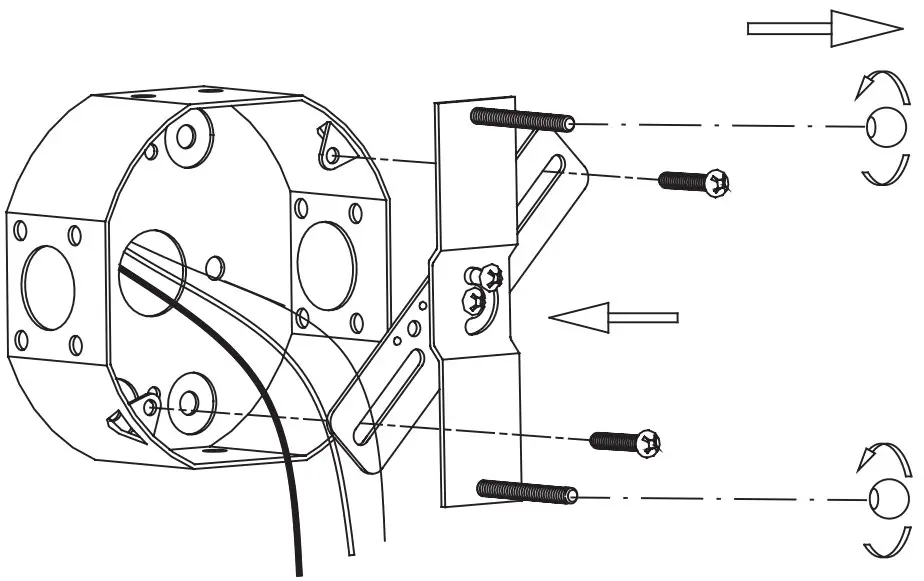
STEP 2
Make the electrical connection from the junction box to the fixture. Connect the ground wire to the mounting unit using the preinstalled green ground screw. Then, connect the positive, negative and ground wires with the supplied wire nuts. Secure with electrical tape.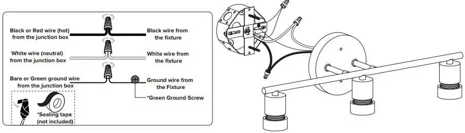
ASSEMBLY INSTRUCTIONS (INSTALLATION)
STEP 3
Attach the fixture to the mounting unit through screw holes as shown, and secure it with ball nuts.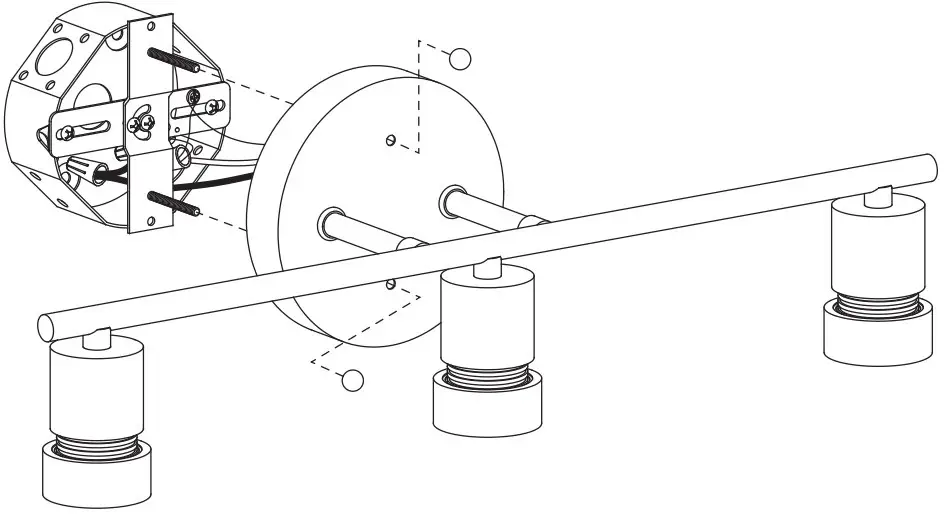
STEP 4
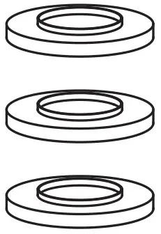
Remove the socket rings from the socket. Attache the cover and glass shade onto fixture using socket rings.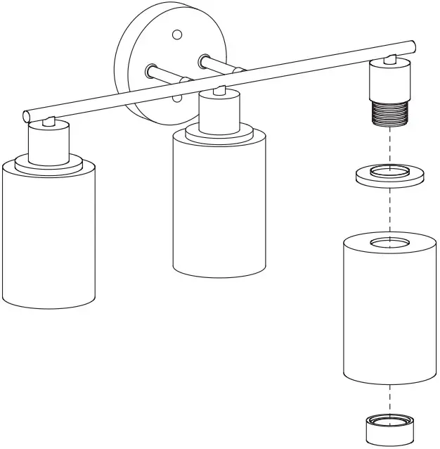
STEP 5
Install bulbs (not included).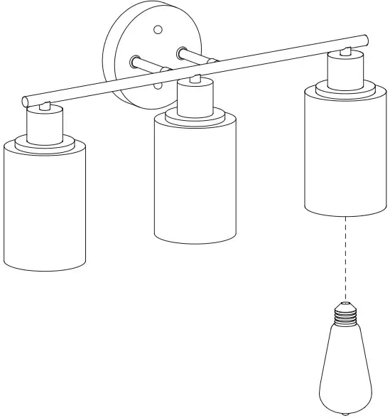
ASSEMBLY AND INSTALLATION
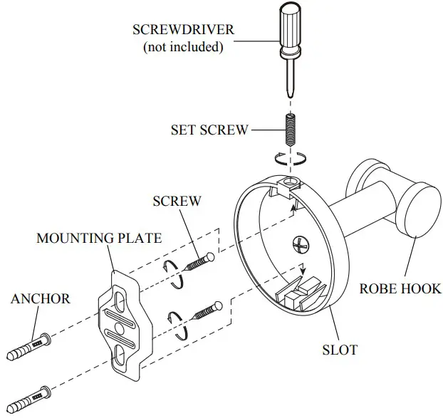
- Place the MOUNTING PLATE on the wall in the desired location, and mark the center of the top and bottom MOUNTING PLATE holes with a pencil. Remove the MOUNTING PLATE from the wall.
- Determine if there is a stud behind the marked hole locations.
2a. If there is a stud behind the marked hole locations, skip to step 5.
2b. If there is NOT a stud behind the marked hole locations, proceed to step 3. - Using a 5/16” DRILL BIT, drill holes at the marked hole locations. the wall.
- Line up the holes in the MOUNTING PLATE with the hole locations, and attach the MOUNTING PLATE to the wall with the SCREWS provided.
- Attach the ROBE HOOK to the MOUNTING PLATE by hooking the SLOT onto the top edge of the
- Finish attaching by inserting and tightening the SET SCREW as shown.
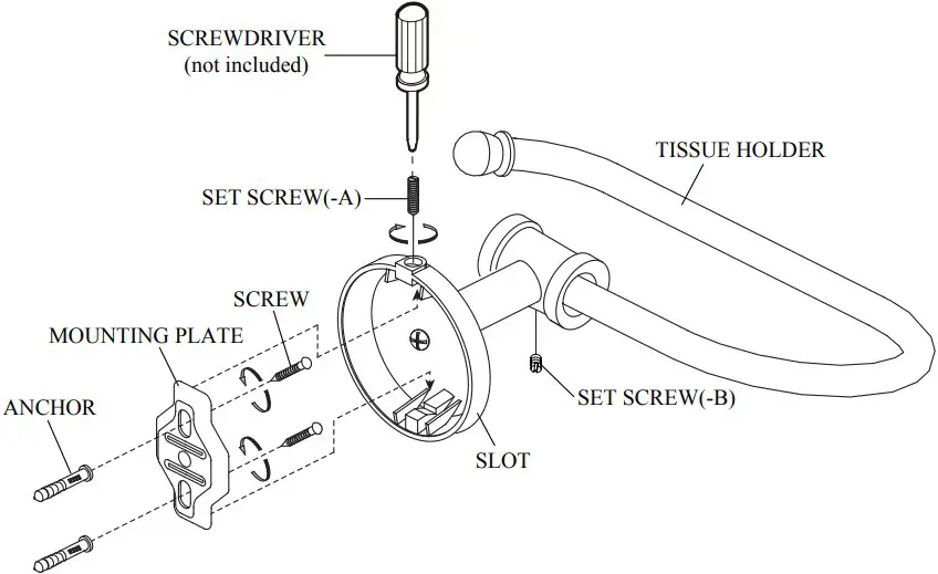
- Place the MOUNTING PLATE on the wall in the desired location, and mark the center of the top and bottom MOUNTING PLATE holes with a pencil. Remove the MOUNTING PLATE from the wall.
- Determine if there is a stud behind the marked hole locations.
2a. If there is a stud behind the marked hole locations, skip to step 5.
2b. If there is NOT a stud behind the marked hole locations, proceed to step 3. - Using a 5/16” DRILL BIT, drill holes at the marked hole locations. the wall.
- Line up the holes in the MOUNTING PLATE with the hole locations, and attach the MOUNTING PLATE to the wall with the SCREWS provided.
- Attach the TISSUE HOLDER to the MOUNTING PLATE by hooking the SLOT onto the top edge of
- Finish attaching by inserting and tightening the SET SCREW-A as shown.
- Orient the TISSUE HOLDER hook in the desired position, and tighten SET SCREW-B.
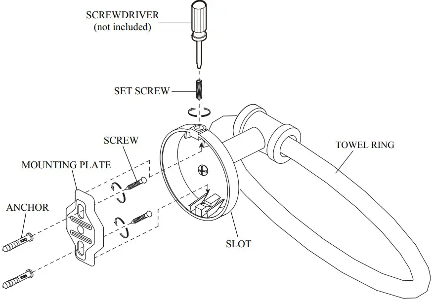
- Place the MOUNTING PLATE on the wall in the desired location, and mark the center of the top and bottom MOUNTING PLATE holes with a pencil. Remove the MOUNTING PLATE from the wall.
- Determine if there is a stud behind the marked hole locations.
2a. If there is a stud behind the marked hole locations, skip to step 5.
2b. If there is NOT a stud behind the marked hole locations, proceed to step 3. - Using a 5/16” DRILL BIT, drill holes at the marked hole locations. the wall.
- Line up the holes in the MOUNTING PLATE with the hole locations, and attach the MOUNTING PLATE to the wall with the SCREWS provided.
- Attach the TOWEL RING to the MOUNTING PLATE by hooking the SLOT onto the top edge of the
- Finish attaching by inserting and tightening the SET SCREW as shown.
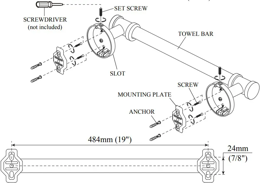
- Place a MOUNTING PLATE on the wall in the desired location, and mark the center of the top and bottom MOUNTING PLATE holes with a pencil. Remove the MOUNTING PLATE from the wall.
- Using a TAPE MEASURE and a LEVEL, measure 19″ to the center of the second MOUNTING PLATE and mark. Place the MOUNTING PLATE on the wall, lining up the center mark, and mark the centers for the top and bottom holes. Repeat for the other MOUNTING PLATE.
- Determine if there is a stud behind the marked hole locations.
2a. If there is a stud behind the marked hole locations, skip to step 6.
2b. If there is NOT a stud behind the marked hole locations, proceed to step 4. - Using a 5/16” DRILL BIT, drill holes at the top and bottom marked hole locations. the wall.
- Line up the holes in the MOUNTING PLATE with the hole locations, and attach the MOUNTING PLATE to the wall with the SCREWS provided.
- Attach the TOWEL BAR to the MOUNTING PLATES by hooking the SLOT onto the top edge of the
- Finish attaching by inserting and tightening the SET SCREWS as shown.