![]() TEC1ACL Series Release of the Select Cellular
TEC1ACL Series Release of the Select Cellular
Installation Guide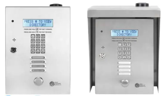
Installation – TEC1ACL Series Access Controllers
Safety Warnings
English Language
For your safety please observe the following recommendations when installing TEC1ACL series product enclosures:
- Never install equipment during a lightning storm or other hazardous event
- Do not bring mains voltage cabling into the product enclosure or attempt to connect mains voltage to any wires leading from the product, or the enclosure housing itself. Only the isolating transformer supplied with the product should be connected to the electrical mains supply by following the installation instructions below In wet locations, only install wiring and cabling rated for wet locations
- Never touch uninsulated telephone wires or terminals unless the telephone line has been disconnected at the telephone network interface
- Follow industry‐recommended installation practices when installing cables and grounding wires
- Do not attempt to use the provided isolating transformer to supply other equipment ‐ it is intended solely for the purpose of powering access controllers in the TEC1ACL series
Cellular Services
Installation of TEC1ACL requires cellular service from your chosen cellular service provider – either AT&T or T‐Mobile.
Out of the Box Active Cellular Capability ‐ Ready to Install
The TEC1ACL is shipped with an ACTIVE cellular SIM card and is ready to use out of the box.
Checking Cellular Reception at Installation Site
Before fully installing the product, check the cellular signal strength at the installation location by simply applying power to the Select Cellular Module Interface (Router) “SCMI” using the 12VDC/2A transformer supplied by SES. Keep in mind your carrier coverage for the site area (AT & T or T-Mobile factory options). You can use the SCMI internal LED indicators to check for cellular service.
Once the SCMI has been powered up for one minute, the “Mobile” LED (green oval) will illuminate if the service is connected and idle.
In the red box, 1, 2 and 3 vertical dashes below the LEDs correspond to low*, medium, and high signal strengths. One bar indicated potentially unreliable service, 2 or 3 bars are recommended.
*An optional External Antenna is available to improve reception.
Select Cellular Module Interface (Router) “SCMI” LED Indications
| LED | Color | Condition | Meaning |
| POWER | Red | Off | No DC power |
| On | DC power is on | ||
| STATUS | Green | Steady Off | No cellular connection/error |
| Steady on | Cellular phone in use | ||
| Long blink on/Long blink off | Data transfer in progress | ||
| Short blink on/long blink off | No SIM card or network searching | ||
| Long blink on/short blink off | In service | ||
| MOBILE | Green | Steady on | The cellular phone is idle |
| Very short blink on / Very short blink off | The cellular phone is in use | ||
| Short blink on/short blink off | Cellular circuits busy | ||
| Long blink on/long blink off | The dialed number is busy | ||
| CPE | Amber | Off | Unit phone line is “on-hook” |
| On | Unit phone line is “off-hook” | ||
| (Signal Strength) | |||
| No bars | All off | Poor or no useable signal | |
| 1-bar LED | Green | On | Low signal but useable* |
| 2-bar LED | Green | On | Good signal |
| 3-bar LED | Green | On | Best signal |
| WAN | Green | Off/On | SES use only |
Note on Fallback Services
The SCMI searches for the best available cellular service but will fall back to 3G services if 4G LTE and VoLTE services are not available. The availability of these services is controlled by cellular carriers, not SES.
Mechanical Mounting
Installation Heights
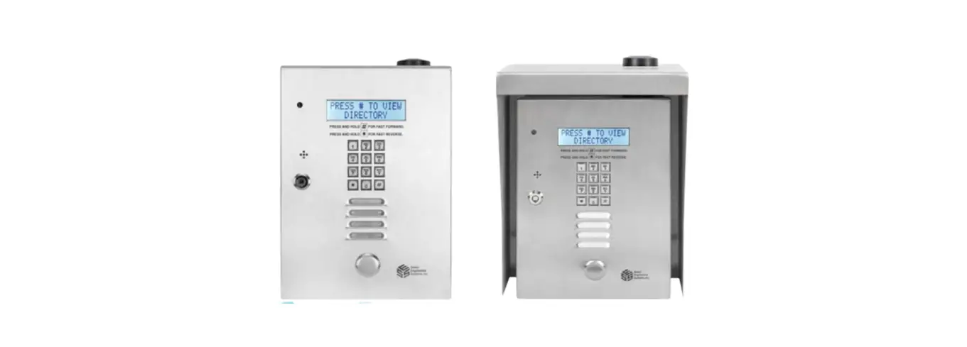
Figure 1 shows the recommended installation heights for the TEC1ACL series access controllers.

Surface Mount
Mount the backbox using the holes provided.
Flush Mount
Cut a hole the size of the backbox 8 ½” (w) x 11 ¾” (h) in the wall, then mount the TEC1ACL in the hole.
Optional Weather Hood Recommendation
It is recommended that an optional weather hood be used when mounting a TEC1ACL in a stand-alone application to protect it from direct exposure to rain and snow. Please call Factory for availability.
Sealing
All openings and penetrations of the TEC1ACL enclosure should be sealed with suitable RTV silicone sealant.
Electrical
Grounding
The TEC1ACL MUST BE AT EARTH GROUND POTENTIAL.
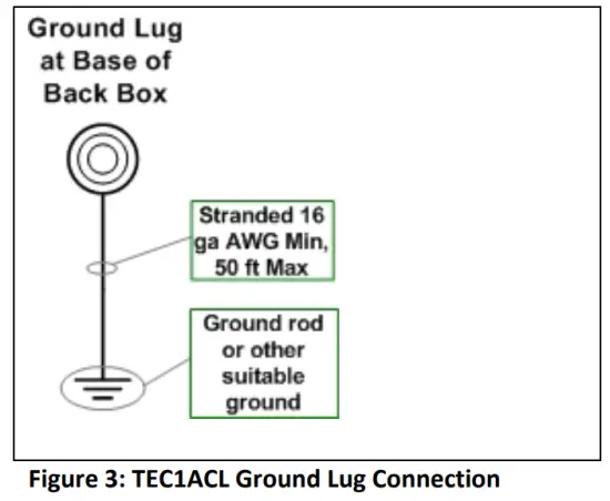
Connect a #16 stranded or larger wire from the ground lug in the base of the backbox of the TEC1ACL to a cold water pipe or other suitable ground. This wire should be less than 50 feet in length. See Figure 2 for the location of the backbox ground lug. 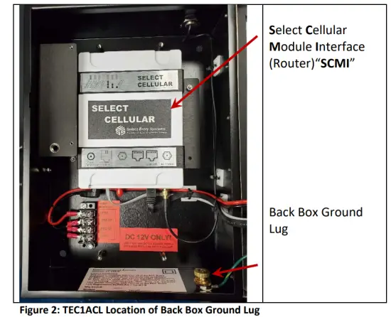
Overall Main Board Layout
See Figure 4 below for an image of the mainboard.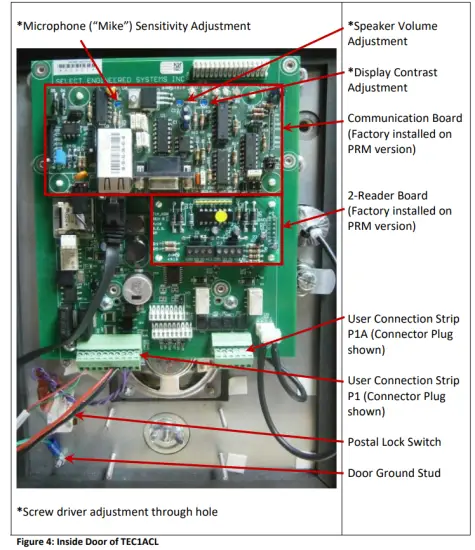
User Connections
Figure 5 shows the Terminal Strip connections P1 and P1A for user connections, along with the Door Ground Stud. No other connections are required. 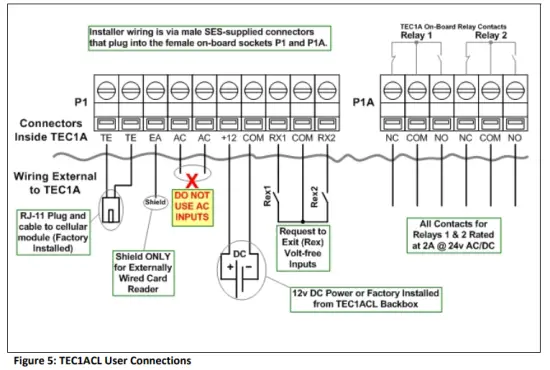
Telephone Connection
The phone cable is already factory-connected to the SCMI at TE-TE in the figure above.
CAUTION Do Not Connect Other Non‐SES Equipment
NO OTHER TELEPHONE DEVICES or NON‐SES EQUIPMENT should be attached to this phone line.
The exception is when connecting additional SES access controllers. In this case, an MUI plug‐in board (included in the PRM version) must be used, allowing up to two SES Access Controllers to be connected on the same line.
TEC1ACL Power
Power must be applied using the SES‐supplied 12VDC/2A transformer. The SES transformer wires should be connected to the terminals “+ POS XR” and “‐ NEG XR” located in the backbox as shown below.
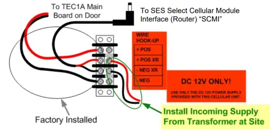
WARNING Do not use AC power on the TEC1ACL unit. There should be NO connections on the “AC” and “AC” terminals of the P1 connector. Damage to the TEC1ACL may occur and void the warranty.
For 12V DC source, idle current consumption is as follows:
| 12V DC IDLE Current Table TEC1ACL | |
| LCD Display | Idle Current (mA) |
| 2-Line | 490 |
| 4-Line | 510 |
Rex (Request to Exit) Inputs
The request to exit inputs (RX1 and RX2) are VOLT‐FREE (dry) contacts located on connector P1 as shown in Figure 5. No external voltage is either required or desired.
To use either Rex input, connect the COM (between RX1 and RX2 of connector P1) to one side of the external relay’s contact being used to request exit, then connect either RX1 or RX2 to the other side of the relay contact as desired. Figure 5 refers.
WARNING – Rex Inputs
Connecting an external voltage source to either Rex input will cause damage and void the warranty.
Relays
Relays are connected to terminals on connector P1A. Both normally open (NO) and normally closed (NC) contacts are available for both relays without the need for board configuration.
WARNING – Relay Contacts Maximum Ratings are 2A @ 24 Volts AC or DC Failure to comply with the maximum ratings shown for relays will cause damage and void the warranty.
Reader Card
The TEC1ACL Premium version includes a 2-Reader Board which works with 26 bit Wiegand format.
The 2‐Reader board installation instructions are included in this booklet or with the individual card packages if ordered separately. Additional information can be found on the SES website www.selectses.com.
Communication Board
The factory-installed Communication Board in the TEC1ACL series includes MUI, Ethernet, and Serial connections, which will allow programming of the unit over the cellular network using SES Selcom software.
SES will provide a SIM Card IP address and a Port number on a label for use in Selcom software setup using the TCP/IP communications method. For more information, visit the SES website www.selectses.com.
Programming a Directory Record with a PIN into a TEC1ACL
The following steps show how to set a directory record (Code, Name, Phone #, and PIN for entrance 1 with 24/7 access) using the keypad. It assumes the TEC1ACL is powered on and that the Welcome Page e.g. “Press # to View Directory” is displayed before starting. Note that Steps 4 and 5 are included to check if PINs are enabled. Once PINs are enabled, steps 4 and 5 can be skipped for future entries. For all other settings please refer to “TEC1ACL Series Menus”.
| Steps to Program a Directory Record with a PIN into a TEC1ACL using the Keypad | |||
| # | Step Description | Keypad Action | Resulting Display |
| 1 | Enter Programming Mode | Press * and 0 at the same time | PASSWORD |
| 2 | Enter Password | Press 6 digit password (default is “777777”) then * | MAIN MENU 1- 8 |
| 3 | Select Codes & Names | Press 1 | CODES & NAMES SELECT 1 – 9 |
| 4 | Skip this step if you know PINs are enabled | Press 8 | ENABLE PINS = 0 or ENABLE PINS = 1 |
| 5 | Complete check of Enable PINs setting | If ENABLE PINS = 0, press 1 then * If ENABLE PINS = 1, press * | CODES & NAMES SELECT 1 – 9 |
| 6 | Select Add New | Press 1 | CODE = |
| 7 | Enter a code e.g. 100 | Press “100” then * | NAME = |
| 8 | Enter a name e.g. JOHN. | Note: # moves cursor to next character Press J# Ott H# N# then * | PHONE if= |
| 9 | Enter phone number | e.g. 3055551212 then * | PIN = |
| 10 | Enter 4-digit PIN | e.g. 1234 then * | ENTRANCE = 0 |
| 11 | Set Entrance 1 | Press 1 then * | TG GROUP = 0 |
| 12 | Set Group 0 (24/7 access) | Press 0 then * | CODE = |
| 13 | Enter more records OR | Repeat as needed from the end of step 6 with new data. Note that no two codes and no two pins can be identical. | |
| 14 | Exit Programming Mode | Press *0 together | Welcome Page |
“BETTER TECHNOLOGY MAKES BETTER SYSTEMS”
 http://www.selectses.com/
Select Engineered Systems, Inc.
Hialeah, FL 33016
Website: www.selectses.com
Email: [email protected]


