![]()
Yokogawa Electric Corporation
User’s
Manual
Model VJU7
Universal Temperature Converter
(Multi-function)
(Isolated Single-output and
Isolated Dual-output Types)
IM 77J01U07-01E
11th Edition: Mar. 2021
Thank you for purchasing the JUXTA Signal Conditioner.
Please read through this manual before use for correct handling.
CAUTIONARY NOTES FOR SAFE USE OF THE PRODUCT
This User’s Manual should be carefully read before installing and operating the product. Please keep this User’s Manual for future reference. For more information of the safety precautions, please refer to the “Precautions on the Use of the JUXTA Series (IM 77J01A00-91Z1)”. The related manuals and general specifications are shown in the table below.
| Doc. Name | Doc. Number |
| Precautions on the Use of the JUXTA Series (User’s Manual) | IM 77J01A00-91Z1 |
| Model VJU7 Universal Temperature Converter(User’s Manual) | IM 77J01U07-01E (This manual) |
| Model VJU7 Universal Temperature Converter(General Specifications) | GS 77J01U07-01E |
User’s manuals in the above table are essential parts of the product; keep it in a safe place for future reference.
This manual is intended for the following personnel;
- Engineers responsible for installation, wiring, and maintenance of the equipment.
- Personnel is responsible for the normal daily operation of the equipment.
The following symbol is used on the product and in this manual to ensure safe usage.
![]() WARNING
WARNING
Calls attention to actions or conditions that could cause serious or fatal injury to the user, and indicates precautions that should be taken to prevent such occurrences.![]() CAUTION
CAUTION
Calls attention to actions or conditions that could cause injury to the user or damage to the instrument or property and indicates precautions that should be taken to prevent such occurrences.
QR Code
The product has a QR Code pasted for efficient plant maintenance work and asset information management.
It enables confirming the specifications of purchased products and user manuals.
For more details, please refer to the following URL.
https://www.yokogawa.com/qr-code
* QR Code is a registered trademark of DENSO WAVE INCORPORATED.
CHECKING THE PRODUCT SPECIFICATIONS AND THE CONTENTS OF THE PACKING
(1) Model and Specifications Check
Check that the model and specifications indicated on the nameplate attached to the side face of the main unit are as ordered.
(2) Contents of the Package
Check that the package contains the following items:
• VJU7: 1 unit
Yokogawa Electric Corporation
2-9-32, Naka-cho Musashino-shi, Tokyo 180-8750 Japan
You can download the latest manuals from the following website:http://www.yokogawa.com/ns/juxta/im/
Standard Accessories:
- Tag number label: 1 sheet
- Range label: 1 sheet
- RJC sensor (when /RJCN is not specified for the optional specification): 1
- User’s manual (IM 77J01U07-01E, this manual): 1 copy
- User’s manual (IM 77J01A00-91Z1): 1 copy
GENERAL
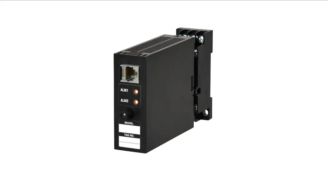
This plug-in type Universal Temperature Converter receives thermocouple, RTD or mV signal and converts it into isolated DC voltage or current signal.
- Settings of the input type (thermocouple, RTD or mV) and measurement range can be changed within the specified ranges.
- One of the DC voltage signals, DC current signals, communication functions (RS-485), and alarm outputs (2 relay contacts) can be selected for the output-2 signal. (Isolated Dual-output Type)
- Various parameters such as input range can be set and modified using a PC (VJ77(sold separately)) and the like).
MODEL AND SUFFIX CODES
| Model | Suffix codes | Description | |||||||
| VJU7 | -0 | x | x | -U | x | x | 0 | /x | Universal Temperature Converter (Multi-function) |
| Fixed code | -0 | Always -0 | |||||||
| Output configuration | 1 | 1 output | |||||||
| 2 | 2 outputs | ||||||||
| Power supply | 6 | 100-240 V AC/DC*1 | |||||||
| 7 | 15-30 V DC*2 | ||||||||
| Input signal | -U | Thermocouple, RTD, mV signal | |||||||
| Output-1 signal | A | 4 to 20 mA DC | |||||||
| 6 | 1 to 5 V DC | ||||||||
| Z | (Custom order)*3 | ||||||||
|
Output-2 signal | A | 4 to 20 mA DC | |||||||
| 6 | 1 to 5 V DC | ||||||||
| P | Communication function (RS485) | ||||||||
| T | Alarm output (2 relay contacts) | ||||||||
| N | No output-2 | ||||||||
| Fixed code | 0 | Always 0 | |||||||
|
Option | /SN | No socket (with socket if not specified) | |||||||
| /C0 | HumiSeal coating*4 | ||||||||
| /FB | Fuse bypass*4 | ||||||||
| /RJCN | No RJC sensor (with RJC sensor if not specified) | ||||||||
| /DF | Fahrenheit display function | ||||||||
- Operating range: 85 to 264V AC/DC
- Operating range: 12 to 36V DC
- DC voltage signal or DC current signal
- When option code /C0 or /FB is specified, the conformity to the safety and EMC standards is excluded. CE marking is not applicable.
Note: An exclusive User’s Manual might be attached to the products whose suffix codes or option codes contain the code “Z” (made to customers’ specifications). Please read it along with this manual.
MOUNTING METHODS
CAUTION
- Plug/disconnect the main unit into/from the socket vertically to the socket face. Otherwise, the terminals may bend and it may cause bad contact.
- The converter shall not tilt 5 degrees or more in either direction when installed.
- When the converter is not connected to the socket, it is necessary to protect the socket against ingress of dust to the connector part.
- Keep this product in a conductive bag when plugged out, during transport or storage.
1.1 Wall Mounting
Loosen the main unit-fixing screw to disconnect the main unit from the socket. Next, anchor the socket onto the wall with screws. Then, plug the main unit into the socket and secure the main unit with the main unit-fixing screw.
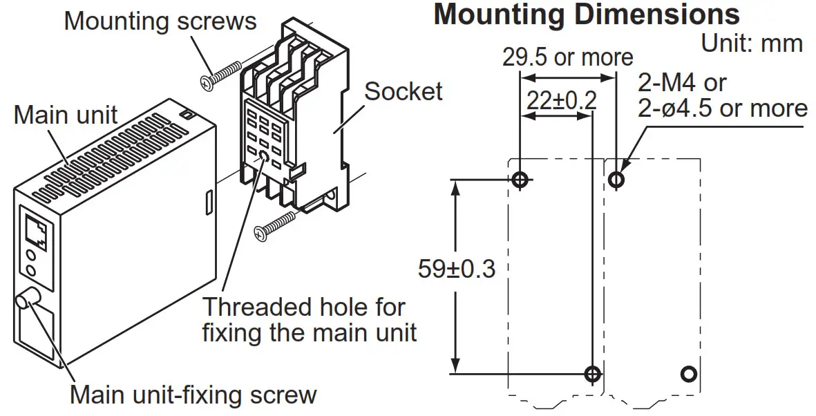
1.2 DIN Rail Mounting
Locate the VJU7 so that the DIN rail fits into the upper part of the DIN-rail groove at the rear of the socket, and fasten the socket using the slide lock at the lower part of the socket.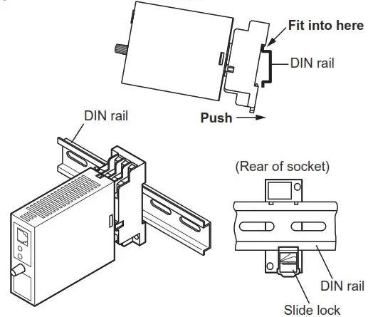
1.3 Mounting Using a Multi-mounting Base
For mounting using a multi-mounting base, see the user’s manual for VJCE (VJ Mounting Base).
1.4 Using a Duct
A wiring duct should be installed at least 30 mm away from the top and bottom faces of the main unit.
INSTALLATION AND ENVIRONMENTAL CONDITIONS
- Avoid the following environments for installation locations:
Areas with vibrations, corrosive gases, dust, water, oil, solvents, direct sunlight, radiation, a strong electric field, and/or a strong magnetic field, direct radiant heat, wind, temperature fluctuation, 2,000 m or more above sea level, outdoors. - If there is any risk of a surge being induced into the power line and/or signal lines due to lightning or other factors, a dedicated lightning arrester should be used as protection for both the product and a field-installed device.
- Operating temperature/humidity range: -10 to 55°C (-10 to 45°C for side-by-side mounting*)/5 to 90%RH (no condensation)
* If the previous model (style S3.xx earlier) is installed together, the ambient temperature is 0 to 40°C. - Continuous vibration: (at 5 to 9 Hz) Half amplitude of 3 mm or less (at 9 to 150 Hz) 9.8m/s 2 or less, 1 oct/min for 90 minutes each in the three-axis directions
- Impact: 98 m/s2 or less, 11 ms, 3 axes, 6 directions, 3 times each
EXTERNAL WIRING
![]() WARNING
WARNING
- To avoid the risk of an electric shock, turn off the power supply and use a tester or similar device to ensure that no power is supplied to a cable to be connected, before carrying out wiring work.
- Do not operate the product in the presence of flammable or explosive gases or vapors. To do so is highly dangerous.
- Use of the product ignoring the specifications may cause overheating or damage. Before turning on the power, ensure the following:
- The power supply voltage and input signal value applied to the product should meet the required specifications.
- The external wiring to the terminals and wiring to the ground areas specifications.
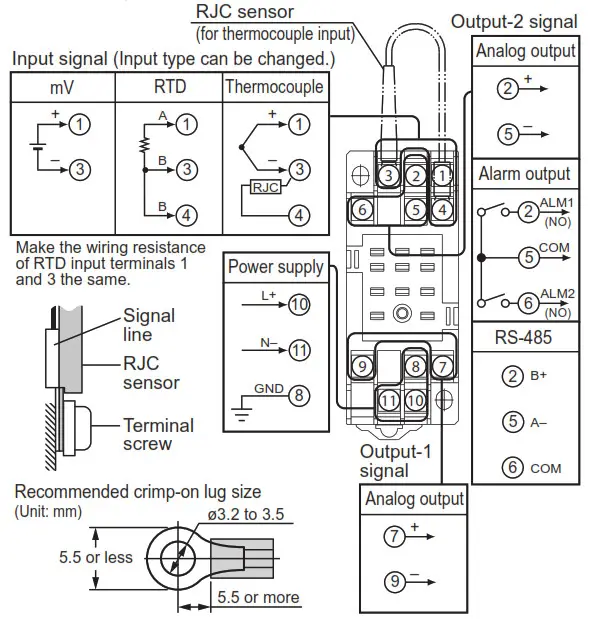
Wiring should be connected to the terminals on the socket of the product. The terminals for external connections are of M3 screws. Use crimp-on terminal lugs for connections to the terminals.
- Recommended cables: A nominal cross-sectional area of 0.5 mm 2 or thicker for signal cables, and that of 1.25 mm 2 or thicker for power cables.
CAUTION
- Do not use output-2 for the isolated single-output type.
- Connect the RJC sensor at the correct position as shown above. Otherwise, the temperature cannot be measured correctly.
- Connect the RJC sensor so that it overlaps the input signal line.
- Handle the RJC sensor lead with care to prevent disconnection.
- The power line and input/output signal lines should be installed away from noise-generating sources. Otherwise, accuracy cannot be guaranteed.
- Make sure to earth ground the ground terminal through minimum resistance. The length and thickness of the grounding cable should be as short and thick as possible. Directly connect the lead from the ground terminal (terminal no. 8) of the product to the ground. Do not carry out daisy-chained inter-ground terminal wiring.
- The product is sensitive to static electricity; exercise care in operating it. Before you operate the product, touch a nearby metal part to discharge static electricity.
- If an inductance (L) load such as auxiliary relays or solenoid valves is used, always insert a spark killer for diminishing sparks, such as a CR filter or a diode in parallel with the inductance load. Otherwise, a malfunction or relay failure may occur. Refer to the following guidelines for a capacitor and resistor:
• C: 0.5 to 1 µF with respect to a contact current of 1 A
• R: 0.5 to 1 Ω with respect to a contact voltage of 1 V - If the ambient temperature is 50 °C or more, please use the cable that the rated temperature is 70 °C or more.
DESCRIPTION OF FRONT PANEL AND CONNECTION OF SETTING OOLS
4.1 Front Panel
The communications connector on the front panel is used for setting up parameters using a PC (VJ77 PC-based Parameters Setting Tool). The alarm indicator lamps for alarm 1 and alarm 2 light up if an alarm occurs (those LEDs are provided only when the output-2 is specified for alarm output (the output-2 suffix code is T).)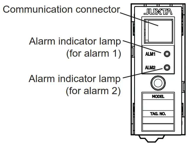
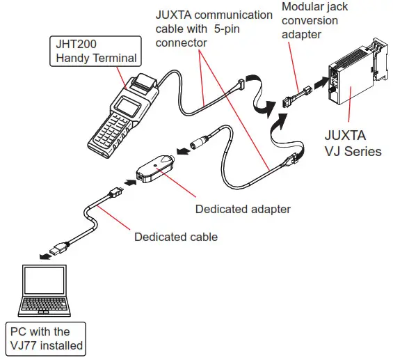
4.2 Connector for Communication
Connect the modular jack conversion adapter to the JUXTA communication cable with 5-pin connector and then connect this adapter to the communication connector of JUXTA.
< How to connect with the setting tool>
<How to connect with the setting tool>
- Use the VJ77 of version R2.02.01 or later.
SETTING PARAMETERS
Set the parameters using a PC (VJ77 PC-based Parameters Setting Tool). Refer to “7. LIST OF PARAMETERS” in this manual and the user’s manual for VJ77 PC-based Parameters Setting Tool (IM 77J01J77-01E).![]() CAUTION
CAUTION
For the input sensor type, input type and temperature unit, the default values of the input range, alarm setpoints and others are predefined according to the values to be selected. Set the parameters as follows.
1. Settings related to inputs: Set the parameters in order starting with (1).
- Input sensor type
- Input type for temperature input
- Temperature unit for temperature input
- Input range
2. Before setting the parameters related to the alarm output and making the adjustments such as wiring resistance correction and output correction, set the parameters
described in 1 above.
If setting the parameters (1) to (3) in 1 above after setting the parameters related to alarm output or making the adjustment, the setpoint will be changed or the adjustment will be reset to the default.
5.1 Settings Related to Input and Output
5.1.1 Input Sensor Type and Input Type
Select the input sensor type in [D07: SENSOR TYPE]. Select TC for thermocouple input, mV for mV input and RTD for RTD input. When you have selected TC in D07, select the TC type to use in [D08: TC TYPE]. When you have selected RTD in D07, select the RTD type to use in [D09: RTD TYPE].
Furthermore, for thermocouple or RTD input, select the temperature unit in [D21: UNIT].
5.1.2 Input Range
Set the 0% value of input range in [D24: INPUT1 L_RNG] and the 100% value of input range in [D25: INPUT1 H_RNG] numerically within the following specified range.
| Input type (TC) | Measurable range (°C) |
| JIS C 1602, IEC 60584-1 (ITS-90) TYPE K | -270 to 1372 |
| JIS C 1602, IEC 60584-1 (ITS-90) TYPE T | -270 to 400 |
| JIS C 1602, IEC 60584-1 (ITS-90) TYPE E | -270 to 1000 |
| JIS C 1602, IEC 60584-1 (ITS-90) TYPE J | -210 to 1200 |
| JIS C 1602, IEC 60584-1 (ITS-90) TYPE R | -50 to 1768 |
| JIS C 1602, IEC 60584-1 (ITS-90) TYPE S | -50 to 1768 |
| JIS C 1602, IEC 60584-1 (ITS-90) TYPE B | 0 to 1820 |
| JIS C 1602, IEC 60584-1 (ITS-90) TYPE N | -270 to 1300 |
| Type W3(Note 1) | 0 to 2300 |
| Type W5(Note 2) | 0 to 2300 |
| Input type (RTD) | Measurable range (°C) |
| JIS C 1604, IEC 60751(ITS-90)PT100 | -200 to 850 |
| JIS C 1604:1989, DIN(IPTS-68) Pt100 | -200 to 660 |
| JIS C 1604:1989, JPt100 | -200 to 510 |
| JIS C 1604:1981, Pt50 | -200 to 649 |
| Input type (mV) | Measurable range (mV) |
| mV | -10 ~ 100 |
Note 1: W3 is the abbreviation of W97Re3-W75Re25 (tungsten97 % rhenium 3 % – tungsten75 % rhenium25 %) ASTM E988 Standard
Note 2: W5 is the abbreviation of W95Re5-W74Re26 (tungsten95 % rhenium 5 % – tungsten74 % rhenium 26 %) ASTM E988 Standard
5.1.3 Software Filter
Set the software filter in [D57: S/W FILTER].
OFF, LOW, MIDDLE, HIGH (default value: OFF)
When LOW, MIDDLE, or HIGH is selected, a first-order filter equivalent to 100 ms, 300 ms, or 1 s is inserted in the input.
5.1.4 Setting Burnout Action
Set the burnout action in [D39:BURN OUT]. Set “OFF”, “UP”, or “DOWN.”![]() CAUTION
CAUTION
- Changing the burnout action direction resets the input adjusted value and the wiring resistance corrected value.
- Changing the input range resets the input adjusted value.
- Execute the wiring resistance correction when the burnout action direction or input wiring is changed.
5.1.5 Direction of Output Action
When output 1 and output 2 are analog outputs, the outputs can be reversed. Set the direction of output action in [D50: OUT1 DR] (output 1) and in [D51: OUT2 DR] (output 2). Select REVERSE for reverse action and DIRECT for direct action.
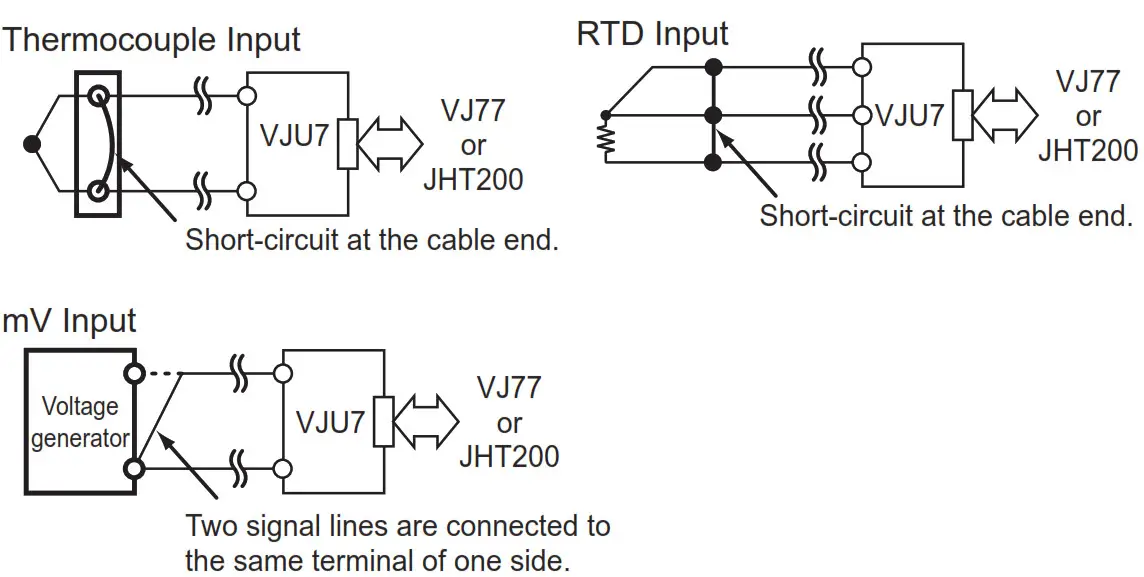
5.1.6 Wiring Resistance Correction
When an error occurs due to the influence of the input wiring resistance, the input can be corrected. Apply a stable input as shown below and select EXECUTE in [P01: WIRING R]. The correction is also required when the direction of burnout action is changed from UP (DOWN) to DOWN (UP) or the wiring for input is changed.
Set the following parameters when the communication function is specified for output 2.
For more information on communication functions, see the user’s manual for VJ Series Communication Functions (IM 77J01J1101E).
5.2.1 Communication Protocol
Select the communication protocol from among PC LINK, PC LINK WITH SUM, MODBUS ASCII, MODBUS RTU, and LADDER in [F01: PROTOCOL].
5.2.2 Communication Address
Set the address number of the converter numerically in a range of 1 to 99 in [F02: ADDRESS].
5.2.3 Baud Rate
Set the baud rate by selecting from among 1200, 2400, 4800, 9600, 19200, and 38400 bps in [F03: BAUD RATE].
5.2.4 Parity
Select the parity from among NONE, EVEN and ODD in [F04: PARITY].
5.2.5 Data Length
Select the data length from among 7 bits and 8 bits in [F05: DATA LEN].
5.2.6 Stop Bit Select the stop bit from among 1 bit and 2 bits in [F06: STOP BIT].
5.2.7 Decimal Point Position
A number of decimals of input value (setting of D register [D0003]) can be set. Select the number of decimals from among 0 to 5 in [F07: INPUT DEC PT].
5.3 Settings Related to Alarm Output
Set the following parameters when the alarm output is specified for the output 2.
5.3.1 Alarm Setpoint Set the alarm-1 setpoint and alarm-2 setpoint numerically in [E01: SET POINT1] and [E02: SET POINT2] for thermocouple input and RTD input or in [E03: SET POINT1] and [E04: SET POINT2] for mV input. Set them in [°C/K] for temperature input or in [%] for mV input.
- Setting range: 0 to 100% of the input range
- Setting resolution: 0.1% (for mV input), 4 significant digits (for temperature input)
5.3.2 Direction of Alarm Action
Select the direction of alarm-1 action and that of alarm-2 action from among HIGH ALM (high-limit alarm) and LOW ALM (low-limit alarm) in [E05: ALM1 ACTION] and [E06: ALM2 ACTION].
- To activate alarm status when input signal ≥ alarm setpoint, select HIGH ALM.
- To activate alarm status when input signal ≤ alarm setpoint, select LOW ALM.
5.3.3 Hysteresis
Set the alarm-1 hysteresis and alarm-2 hysteresis numerically in [E07: HYSTERESIS1] and [E08: HYSTERESIS2] for thermocouple input and RTD input or in [E09: HYSTERESIS1] and [E10: HYSTERESIS2] for mV input.
Hysteresis is a value-added to the alarm setpoint in order for an alarm status to be released (to normal) after the alarm status has been activated. The alarm status will be released in the following conditions, depending on the direction of alarm action.
* When HIGH ALM (high-limit alarm) is set: Alarm is released when input signal < (alarm setpoint – hysteresis).
* When LOW ALM (low-limit alarm) is set: Alarm is released when input signal > (alarm setpoint + hysteresis).
Set them in [°C/K] for temperature input or in [%] for mV input.
• Setting range: 0 to 100% of the input range
• Setting resolution: 0.1% (for mV input), 4 significant digits (for temperature input)
5.3.4 Alarm ON Delay and Alarm OFF Delay Set the alarm-1 ON delay and alarm-2 ON delay numerically in
[E11: ON DELAY1] and [E12: ON DELAY2]. Set the alarm-1 OFF delay and alarm-2 OFF delay numerically in [E13: OFF DELAY1] and [E14: OFF DELAY2].
An alarm ON delay is a delay time from the establishment of alarm conditions to its output; an alarm OFF delay is a delay time from the establishment of return-to-normal conditions to its output.
• Setting range: 0 to 999 seconds
• Setting resolution: 1 second (However, about 0.2 seconds is to be added to the set time to prevent the wrong operation.) For example, when an alarm ON delay is set to 1 second,
the alarm output is generated if alarm status continues for 1 second or more after the input value exceeds the alarm setpoint. Furthermore, when an alarm OFF delay is set to 2 seconds, the alarm output is released if the normal condition continues for 2 seconds or more after the input value has returned to normal from the alarm status.
5.3.5 Direction of Relay Action
Select the direction of relay energizing in alarm-1 normal condition and alarm-2 normal condition from among NRM DEENERGIZED (de-energized under normal condition) and NRM ENERGIZED (energized under normal condition) in [E15: RL1 ACTION] and [E16: RL2 ACTION].
DESCRIPTION OF ALARM ACTIONS
This chapter describes examples of alarm actions under the following conditions.
| Item | Alarm 1 | Alarm 2 | ||
| Parameter | Setpoint | Parameter | Setpoint | |
| Direction of alarm action | E05: ALM1 ACTION | High-limit alarm | E06: ALM2 ACTION | Low-limit alarm |
| Alarm setting | E03: SET POINT1 | 80% | E04 : SET POINT2 | 15% |
| Hysteresis | E09: HYSTERESIS1 | 10% | E10 : HYSTERESIS2 | 5% |
| Alarm ON delay | E11: ON DELAY1 | 1 sec | E12 : ON DELAY2 | 3 sec |
| Alarm OFF delay | E13: OFF DELAY1 | 2 sec | E14 : OFF DELAY2 | 4 sec |
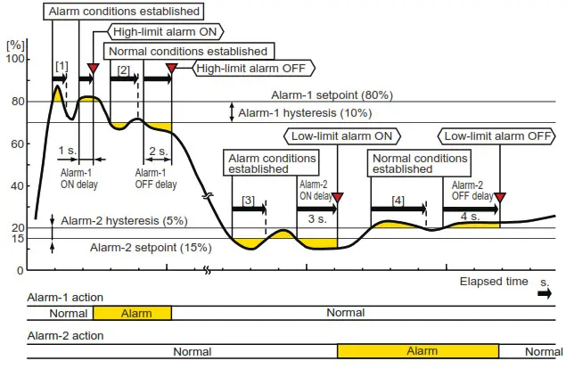
| Description of alarm actions | The alarm is output if the condition where the input value is 80% or more of high-limit alarm continues for 1 second or more. After the alarm is output when the condition where the input value is less than 70% of the high-limit alarm continues for 2 seconds or more, the status returns to normal. | The alarm is output if the condition where the input value is 15% or less of low-limit alarm continues for 3 seconds or more. After the alarm is output when the condition where the input value is more than 20% of the low-limit alarm continues for 4 seconds or more, the status returns to normal. | ||
Figure 6.1
- Alarm status does not continue for more than 1 second after the alarm conditions are established at alarm 1.
- Normal status does not continue for more than 2 seconds after the normal conditions are established at alarm 1.
- Alarm status does not continue for more than 3 seconds after the alarm conditions are established at alarm 2.
- Normal status does not continue for more than 4 seconds after the normal conditions are established at alarm 2.
LIST OF PARAMETERS
| Parameter Display | Item | ||
| MODEL | Model | ||
| TAG NO | Tag no. | ||
| SELF CHK | Self-check result | ||
| A | DISPLAY1 | Display 1 | *2 |
| A01 | INPUT1 | Input value 1 | |
| A09 | OUTPUT1 | Output value 1 | |
| A10 | OUTPUT2 | Output value 2 | |
| A15 | ALM1 STATUS | Alarm-1 status | |
| A16 | ALM2 STATUS | Alarm-2 status | |
| A54 | STATUS | Status | *1 |
| A56 | REV NO | Rev. no. | |
| A58 | MENU REV | MENU REV | |
| A60 | SELF CHK | Self-check result | |
| B | DISPLAY2 | Display 2 | *2 |
| B01 | INPUT1 | Input value 1 | |
| B09 | OUTPUT1 | Output value 1 | |
| B10 | OUTPUT2 | Output value 2 | |
| B15 | ALM1 STATUS | Alarm-1 status | |
| B16 | ALM2 STATUS | Alarm-2 status | |
| B60 | SELF CHK | Self-check result | |
| D | SET (I/O) | Setting (I/O) | *2 |
| D01 | TAG NO.1 | Tag no. 1 | |
| D02 | TAG NO.2 | Tag no. 2 | |
| D03 | COMMENT1 | Comment 1 | |
| D04 | COMMENT2 | Comment 2 | |
| D07 | SENSOR TYPE | Input sensor type | |
| D08 | TC TYPE | Thermocouple type | |
| D09 | RTD TYPE | RTD type | |
| D21 | UNIT | Temperature unit | |
| D24 | INPUT1 L_RNG | Input 1 low range | |
| D25 | INPUT1 H_RNG | Input 2 high range | |
| D32 | OUT1 L_RNG | Output-1 low range | *3 |
| D33 | OUT1 H_RNG | Output-1 high range | *3 |
| D34 | OUT2 L_RNG | Output-2 low range | *3 |
| D35 | OUT2 H_RNG | Output-2 high range | *3 |
| D39 | BURN OUT | Burnout | |
| D40 | LINEARIZE | Linearize (mV) | |
| D50 | OUT1 DR | The direction of output-1 action | |
| D51 | OUT2 DR | The direction of output-2 action | |
| D57 | S/W FILTER | Software filter | |
| D59 | NMRR | Frequency setting | *3 |
| D60 | SELF CHK | Self-check result | |
| E | SET (I/O) | Setting (alarm output) | *2 |
| E01 | SET POINT1 | Alarm-1 setting (Temperature) | |
| E02 | SET POINT2 | Alarm-2 setting (Temperature) | |
| E03 | SET POINT1 | Alarm-1 setting (%) | |
| E04 | SET POINT2 | Alarm-2 setting (%) | |
| E05 | ALM1 ACTION | The direction of alarm-1 action | |
| E06 | ALM2 ACTION | The direction of alarm-2 action | |
| E07 | HYSTERESIS1 | Alarm-1 hysteresis (Temperature) | |
| E08 | HYSTERESIS2 | Alarm-2 hysteresis (Temperature) | |
| E09 | HYSTERESIS1 | Alarm-1 hysteresis (%) | |
| E10 | HYSTERESIS2 | Alarm-2 hysteresis (%) | |
| E11 | ON DELAY1 | Alarm-1 ON delay setting | |
| E12 | ON DELAY2 | Alarm-2 ON delay setting | |
| E13 | OFF DELAY1 | Alarm-1 OFF delay setting | |
| E14 | OFF DELAY2 | Alarm-2 OFF delay setting | |
| E15 | RL1 ACTION | The direction of alarm-1 relay action | |
| E16 | RL2 ACTION | The direction of alarm-2 relay action | |
| E60 | SELF CHK | Self-check result | |
| F | SET(COM) | Setting (communication) | *2 |
| F01 | PROTOCOL | Communication protocol | |
| F02 | ADDRESS | Address | |
| F03 | BAUD RATE | Baud rate | |
| F04 | PARITY | Parity | |
| F05 | DATA LEN | Data Length | |
| F06 | STOP BIT | Stop bit | |
| F07 | INPUT DEC PT | Decimal point position of input | |
| F60 | SELF CHK | Self-check result | |
| P | ADJUST | Adjustment | *2 |
| P01 | WIRING R | Wiring resistance correction | |
| P04 | IN1 ZERO ADJ | Zero adjustments of input-1 | |
| P05 | IN1 SPAN ADJ | Span adjustment of input-1 | |
| P30 | OUT1ZERO ADJ | Zero adjustments of output-1 | |
| P31 | OUT1SPAN ADJ | Span adjustment of output-1 | |
| P32 | OUT2ZERO ADJ | Zero adjustments of output-2 | |
| P33 | OUT2SPAN ADJ | Span adjustment of output-2 | |
| P60 | SELF CHK | Self-check result | |
| Q | TEST | Test | *2 |
| Q01 | RJC | ON/OFF of RJC | |
| Q04 | OUT1 TEST | Forced output (output-1) | |
| Q05 | OUT2 TEST | Forced output (output-2) | |
| Q10 | ALM1 TEST | Forced output (alarm-1) | |
| Q11 | ALM2 TEST | Forced output (alarm-2) | |
| Parameter Display | Item | |
| Q60 | SELF CHK | Self-check result |
- The Status is displayed for service personnel to see history records.
- There are items not displayed depending on what input sensor type and output-2 are specified.
- The parameters are the items to be set at the factory.
MAINTENANCE
The product enters the operable status as soon as the power is turned on, but requires 10 to 15 minutes of warm-up to meet the performance requirements.
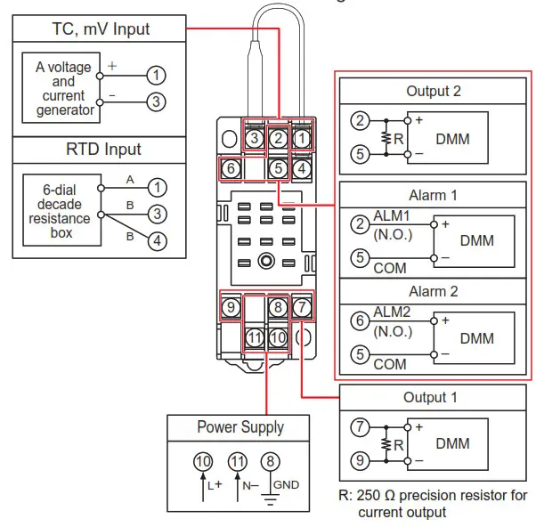
8.1 Calibration Apparatus
- A voltage and current generator (YOKOGAWA GS200 or the equivalent): 1
- 6-dial decade resistance box (YOKOGAWA 279301 or equivalent): 1
- Digital Multimeter (YOKOGAWA 7561 or equivalent): 1
- A precision resistor of 250 Ω ±0.01%, 1 W: 1
- Setting tool for adjustment (Refer to “4.2 Connector for Communication” in this manual.)
8.2 Calibration Procedure
- Connect the instruments as shown in the figure below.

- For TC current
• Turn off the RJC through the setting tool.
• Use the DC voltage/current standard and apply input signals (electromotive force) equivalent to 0, 25, 50, 75, and 100% of the input to the converter.
For RTD input
• Use a 6-dial decade resistance box and apply input signals (resistance value) equivalent to 0, 25, 50, 75, and 100% of the input to the converter.
For mV input
Use the DC voltage/current standard and apply input signals equivalent to 0, 25, 50, 75, and 100% of the input span to the converter. - Check to see the corresponding output voltages are 0, 25, 50, 75, and 100% respectively, and within the specified accuracy rating. (“R” is used for current output.)
For alarm output, check the relay action by the alarm indicator lamp or resistance of output terminals.
• When adjusting the output signal, use the VJ77 parameter setting tool.
For adjustment using a setting tool, refer to the User’s Manual for setting tool and “7. LIST OF PARAMETERS” in this manual. User’s Manual for VJ77 [Document No.: IM 77J01J77-01E]
SAFETY AND EMC STANDARDS
The following will be acquired.
Safety:
IEC/EN 61010-1 compliance (CE)
IEC/EN 61010-2-030 compliance (CE)
CAN/CSA-C22.2 No.61010-1 (CSA)
CAN/CSA-C22.2 No.61010-2-030 (CSA)
UL61010-1 (CSA NRTL/C)
UL61010-2-030 (CSA NRTL/C)
Overvoltage category: II
Pollution degree: 2
Measurement category: O (other) Rated power voltage: 15-30 V DC (±10%) 2.5 W or 100-240V AC/DC (±10%) 50/60 Hz 2.6 W 6.7 VA
Rated voltage (Input signal) : ±0.15 V DC
Rated voltage (Analog output signal): −10 to +10 V DC, 0 to 20 mA DC
Rated voltage (Alarm output signal) : 30 V DC 1A
Rated voltage (Communication output signal) : 5 V DC
Rated transient overvoltage: 1500 V (*)
* This is a reference safety standard value for the measurement Category O. This value is not necessarily a guarantee of instrument performance.
![]() CAUTION
CAUTION
This instrument is for Measurement Category O (other). Do not use it for measurements in locations falling under Measurement Categories II, III, and IV.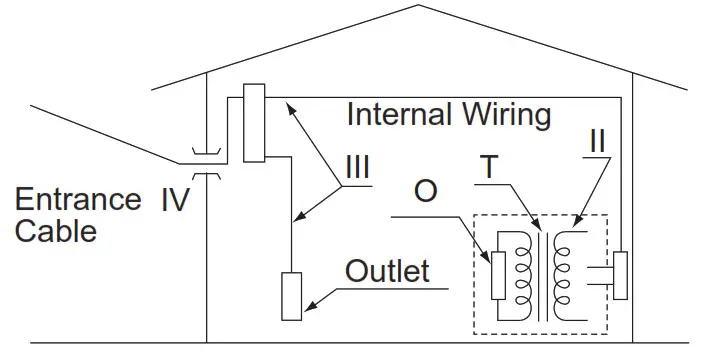
| Measurement category | Description | Remarks | |
| O | (other) | For measurements performed on circuits not directly connected to MAINS. | |
| II | CAT.II | For measurements performed on circuits directly connected to the low-voltage installation. | Appliances, portable equipment, etc. |
| III | CAT.III | For measurements performed in the building installation. | Distribution board, circuit breaker, etc. |
| IV | CAT.IV | For measurements performed at the source of the low-voltage installation. | Overhead wire, cable systems, etc. |
EMC standards:
• CE:
EN 61326-1 Class A, Table 2
EN 61326-2-3
* The instrument continues to operate at a measurement accuracy of within ±20% of the range during testing.
EN 55011 Class A, Group 1
EN 61000-3-2
EN 61000-3-3
• RCM:
EN 55011 Class A, Group 1
• KC:
Electromagnetic wave interference prevention standard, electromagnetic wave protection standard
![]() CAUTION
CAUTION
Caution to comply with EMC standards: When operating this instrument by the external power supply, use an independent power unit conforming to CE marking. Be sure to use the lightning arrester to comply with EMC standards.
Note: When option code /C0 or /FB is specified, the conformity to the safety and EMC standards is excluded.
ENVIRONMENT STANDARD
EU RoHS directive: EN IEC 63000
(However, when option code /C0 or /FB is specified, CE marking is not applicable because the product does not comply with the Safety and EMC standards.)
TRANSPORT AND STORAGE CONDITIONS
- Temperature: -25 to 70°C
- Temperature change rate: 20°C per hour or less
- Humidity: 5 to 95%RH (no condensation)
![]() CAUTION
CAUTION
Keep this product in a conductive bag when plugged out, during transport or storage.
IM 77J01U07-01E 11th Edition


