GEWiSS GW A9126 CHORUSMART Switch and Roller Shutters Actuator

Introduction
- Device safety is only guaranteed when the safety and usage instructions are respected, so keep them handy. Make sure these instructions are received by the installer and end user.
- This product must only be used for the purpose for which it was designed. Any other form of use should be considered improper and/or dangerous. If you have any doubts, contact the GEWISS SAT technical support service.
- The manufacturer cannot be held liable for any damage if the product is improperly or incorrectly used or tampered with.
- The product must not be modified. Any modification will annul the warranty and may make the product dangerous.
- Responsibility for the issuing of the product on the European Union market lies with:
![]() GEWISS S.p.a. Via A. Volta, 1 – 24069 Cenate Sotto (BG) – Italy
GEWISS S.p.a. Via A. Volta, 1 – 24069 Cenate Sotto (BG) – Italy
Tel.: +39 035 946 111 – Fax: +39 035 946 270
E-mail: [email protected] – Website: www.gewiss.com
ATTENTION: the device must only be installed by qualified personnel, observing the current regulations and guidelines for KNX installations.
![]() ATTENTION: the unused BUS signal cables, and the electrical continuity conductor, must never touch any live elements or the earthing conductor
ATTENTION: the unused BUS signal cables, and the electrical continuity conductor, must never touch any live elements or the earthing conductor![]() ATTENTION: disconnect the mains voltage before installing the device or carrying out any work on it.
ATTENTION: disconnect the mains voltage before installing the device or carrying out any work on it.
PACK CONTENTS
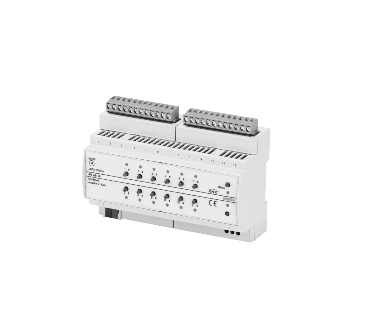
- 1 combined KNX 6/12-channel 8AX actuator – from DIN rail
- 1 BUS terminal
- 2 screw terminals
- 1 installation manual
BRIEFLY
The combined KNX 6/12-channel actuator from DIN rail is fitted with 12 independent 8AX relays with 1 NO output contact, for controlling:
– 12 loads in ON/OFF switching mode at 230V AC, or
– 6 roller shutters/Venetian blinds with 230V AC motors
Each single pair of channels can be separately configured; this means that combinations of various types of output channel (configured for switching or roller shutter command) can be freely created. The device is fitted with 12 front push-buttons for directly activating the relays for switching or commanding the roller shutters (up/ down/stop), and 12 green LEDs that indicate the output activation status or a moving roller shutter. Loads can be commanded via the local command push-buttons, even in the absence of the BUS voltage: in this case the device requires the 230V AC auxiliary power supply provided by the special terminals. The module is assembled on the DIN rail, inside the electric boards or junction boxes. The device is fitted with (figure A)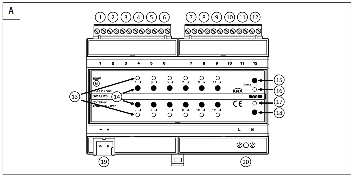
1. Output relay 1
2. Output relay 2
11. Output relay 11
12. Output relay 12
13. LED for relay status/movement in progress
14. Local command push-buttons
15. Status push-button
16. Status LED
17. LED for programming physical address
18. Button key for programming physical address
19. BUS terminals
20. Auxiliary power supply
FUNCTIONS
The actuator is configured with the ETS software to create the functions listed below:
Functions of each single channel when configured as ON/OFF switching
- ON/OFF switching
- activation/deactivation delay
- timed switching (stair raiser light)
- flashing
- scenes
- logic functions for each output
- safety function
- priority command (forcing)
- block function
- count of the output activation time or the number of relay operations
- output status signal
Functions of each pair of channels when configured as roller shutters/Venetian blinds
- up/down movement and stop
- position adjustment with percentage commands
- slat adjustment with percentage and step commands
- scenes
- safety function
- priority command (forcing)
- block function
- weather alarm management (wind, rain, ice)
- automatic mode
- automatic calibration
- count of the up/down movement time or the number of relay operations
- signal of percentage position of the load and the slats
The behaviour of the local command push-buttons can be configured via ETS. By default, all six pairs of channels are configured to control a Venetian blind, and the behaviour of the local push-buttons on the device is:
- with a long press on the push-button (> 0.5 s), the actuator moves the roller shutter or Venetian blind UP or DOWN for the set movement time
- if the roller shutter or Venetian blind is moving, a brief press on one of the two pushbuttons (= 0.5 s) stops the movement
- with the Venetian blind stationary, every brief press on the push-buttons (= 0.5 s) adjusts the tilt of the slats
ATTENTION: loads can be commanded via the local command push-buttons, even in the absence of the BUS voltage: in this case the device requires the 230V AC auxiliary power supply provided by the special terminals. BEHAVIOUR ON BUS SUPPLY FAILURE AND RESET
The behaviour of the outputs on BUS supply voltage failure and reset can be configured via ETS. By default, any movement of the roller shutter or Venetian blind is interrupted when the BUS voltage fails; when the voltage supply is restored, no action is performed.
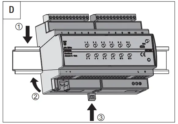
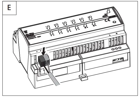
ASSEMBLY
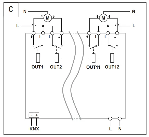
For assembly, refer to figure D. To connect the KNX BUS terminal, refer to figure E. For the electrical connections, refer to figure B if the channels are configured for on/off switching, or figure C if they are configured for roller shutter/Venetian blind command.
ATTENTION: to ensure the relay switching times, you are advised to connect the 230V AC auxiliary voltage supply.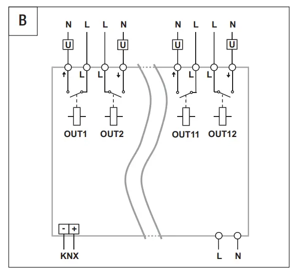
MAINTENANCE
The device does not require any maintenance. Use a dry cloth if cleaning is required.
PROGRAMMING
The device must be configured with the ETS software. Detailed information about the configuration parameters and their values is given in the Technical Manual (www.gewiss.com). For safety matters linked to the operation of the roller shutters or Venetian blinds, the functioning of the channels must be configured via ETS and also via the local push-buttons. The device will only work properly if local configuration coincides with the configuration set via ETS.
Modification mode input
Press the Status push-button for at least 5 seconds
2. Wait for the Status LED to light up with a green colour
3. Opening of all the relays associated with the outputs
4. Activation of the LEDs according to the configuration active at that moment
Parameter personalization
- Cyclically change the configuration of the associated channels by pressing one of the two channels repeatedly, as indicated in the table:
LED 1 and LED 2 | LED 3 and LED4 | LED 5 and LED 6 | LED 7 and LED 8 | LED 9 and LED 10 | LED 11 and LED 12 | CONFIGURATION OF THE ASSOCIATED CHANNELS |
Fixed green | Switching (independent) | |||||
| Alternated green blinking (1 Hz) | Roller shutters/Venetian blinds (combined) | |||||
Modification mode output
- to quit
a. saving the new settings, press the Status push-button
b. without saving, wait 30 seconds from the last pressing of a push-button - the end of configuration mode is signaled when the Status LED switches off During this configuration phase, the messages from the BUS are ignored. When the configuration phase is abandoned, the relays remain open. After downloading the ETS application software or modifying the local channel configuration, the device compares the channel functioning set via ETS and set locally; any incoherency between the two configurations is signaled by:
- a fixed red light on the status LED
- a blinking green light on the LEDs of channels that are not correctly programmed.
Channels displaying an error are not managed, and the local push-buttons are disabled. Modify the ETS or local configuration to restore correct channel functioning.
TECHNICAL DATA
| Communication | KNX BUS |
| Power supply | Via KNX BUS, 29V DC SELV |
| BUS current absorption | 10 mA (with auxiliary power supply) |
| Auxiliary power supply | 230V AC |
| BUS cable | KNX TP1 |
| Command elements | 1 miniature button key for programming physical address |
| 12 push-buttons for local command | |
| 1 status push-button | |
| Display elements | 1 red LED for programming physical address |
| 12 green LEDs for signaling output status | |
| 1 red/green status LED (State) | |
| Implementation elements | 12 relays (8AX) with voltage-free NO contact |
| Max. switching current | 8A (AC1) |
| 8AX (140 μF ref. EN 60669-1) fluorescent loads with maximum surge current 300A (150 μs) | |
| Max. power for the type of load | Incandescent lamps (230V AC): 1500W |
| Halogen lamps (230V AC): 1500W | |
| Loads controlled by toroidal transformers: 1200W | |
| Loads controlled by electronic transformers: 1000W | |
| Energy efficient lamps (compact fluorescent): 25x23W | |
| LED lamps (230Vac): 25x10W | |
| Motors: 800W | |
| Maximum dissipated power | 10W |
| Usage environment | Dry indoor places |
| Operating temperature – | -5 to +45°C |
| Storage temperature | -25 to +55°C |
| Relative humidity | Max. 93% (non-compensative) |
| Connection to the BUS | Coupling terminal, 2 pins Ø 1mm |
| Electric connections | Extractable screw terminals, max. cable section: 4mm |
| Screw terminals, max. cable section: 2.5mm | |
| Degree of protection | IP20 |
| Size | 8 DIN modules |
| Reference Standards | Low Voltage Directive 2014/35/EU |
| Electromagnetic Compatibility Directive 2014/30/EU, EN 50491, EN 60669-2-5 | |
| Certifications | KNX |
Customer Support
According to applicable UK regulations, the company responsible for placing the goods in UK market is:
GEWISS UK LTD – Unity House, Compass Point Business Park, 9 Stocks Bridge Way, ST IVES Cambridge shire, PE27 5JL, United Kingdom tel: +44 1954 712757 E-mail: [email protected]
![]() +39 035 946 11
+39 035 946 11
8:30 – 12:30 / 14:00 – 18:00![]() www.gewiss.com
www.gewiss.com![]()