![]()
myTEM Radio Switch Shutter Plus
MTSWIS-101-WL
The myTEM Radio Switch Shutter Plus is a universal, Z-Wave compatible wall or ceiling switch and is used to control the motor of blinds, Venetian blinds, roller shutters, awnings, etc. These are controlled via a myTEM Radio Server, via switches or buttons connected to the inputs, or via the optional myTEM Touch Add-on, which can be connected to the rear socket.
The device is intended for installation in a flush-mounted box.
SAFETY INSTRUCTIONS
- Operate this device only as described in the manual.
- Do not operate this device if it has obvious damage.
- This device shall not be altered, modified, or opened.
- This device is intended for use in buildings in a dry, dust-free location.
- This device is intended for installation in a flush-mounted box. After installation, it must not be openly accessible.
DISCLAIMER
All rights reserved. This is a translation from the original version in German.
This manual may not be reproduced in any format, either in whole or in part, nor may it be duplicated or edited by electronic, mechanical, or chemical means, without the written consent of the publisher. The manufacturer, TEM AG, is not liable for any loss or damage caused by failure to follow the instructions in the manual. Typographical and printing errors cannot be excluded. However, the information contained in this manual is reviewed on a regular basis and any necessary corrections will be implemented in the next edition. We accept no liability for technical or typographical errors or the consequences thereof. Changes may be made without prior notice as a result of technological advances. TEM AG reserves the right to make changes to product design, layout, and driver revisions without notice to its users. This version of the manual supersedes all previous versions.
Product description
The myTEM Radio Switch Shutter Plus is a universal, Z-Wave compatible wall or ceiling switch and is used to control the motor of blinds, Venetian blinds, roller shutters, awnings, etc. Optionally, a myTEM Touch Add-on control panel with five buttons can be attached to the connector. It can be used to control the outputs or independent functions. The two digital inputs are configured to control the outputs, but can also be used independently.
The programmable behavior to the wireless commands allows flexible use in the house. At the same time, the device also serves as a Z-Wave repeater to improve the range and stability of the Z-Wave network.
The device is intended for installation in a flush-mounted box, e.g. behind light switches or sockets.
Preparation for the installation
In order to include (“Add”) a Z-Wave device to a network, it must be in the factory default state. Please make sure to reset the device into factory default. After power-up the status is displayed as below:
Status “Add” (included in a Z-Wave network): The LED lights green for 1-2 seconds
Status “Remove” (not included): The LED flashes red for 1-2 seconds.
WARNING! Depending on national safety standards, only authorized and/or trained technicians may be allowed to make electrical installations on the power supply. Please inform yourself about the legal situation before installation.
Installation
- WARNING! To avoid electrical shock and/or equipment damage, disconnect power to the main fuse or circuit breaker before installation or maintenance. Prevent the fuse from being accidentally switched on again and check that the system is de-energized.
- WARNING! The device shall be connected according to the wiring diagram only. Switches/buttons in the installation must comply with relevant safety standards.
- WARNING! The electrical installation must be protected with a fuse of max. 10 A.
- WARNING! The myTEM Radio Switch Shutter Plus should be installed in a flush-mounted box (wall, ceiling) in compliance with relevant national safety standards and with a depth of not less than 60 mm. The length of the cables between the device and a switch or the load should not exceed 10 m.
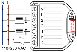
- CAUTION! Maximum loads shall not exceed 6 A, 250 VAC, (cos(φ) = 1.0). Due to the end position detection, only one single motor shall be connected, not several in parallel.
 |  |
Inclusion/Exclusion (“Add/Remove”) of the device
On factory default, the device does not belong to any Z-Wave network. In order to communicate with other Z-Wave devices, it must be included in an existing network or a new network has to be established. In Z-Wave, this process is called “Add”.
Devices can also be removed from networks. In Z-Wave, this process is called “Remove”. Both processes are initiated by the primary controller of the Z-Wave network. This controller is put into the “Add”, respectively the “Remove” mode. The manual of the controller will contain the information on how to switch it into these modes. Only when the primary controller of the Z-Wave network is in the “Add” mode can devices be added. Removing a device from the network will re-set it to the delivery state.
SmartStart
SmartStart enabled products can be added into a Z-Wave network by scanning the Z-Wave QR code Further information can be found on our website:
 https://www.mytem-smarthome.com/web/en/download
ATTENTION:
This device is not a toy. Please keep it away from children and animals!
Please read the manual before attempting to install the device!
These instructions are part of the product and must remain with the end-user.
Warning and safety instructions
WARNING!
This word indicates a hazard with a risk that, if not avoided, can result in death or serious injury. Work on the device must only be carried out by persons with the necessary training or instruction.
CAUTION!
This word warns of possible damage to property.
| 115’429 | Version: 03/2021 |
Trademarks
myTEM and TEM are registered trademarks. All other product names mentioned herein may be trademarks or registered trademarks of their respective companies.
What is Z-Wave?
What is Z-Wave?
Z-Wave is the international wireless protocol for communication in the smart home. Z-Wave ensures reliable communication by reconfirming every message (two-way communication) and every mains powered node can act as a repeater for other nodes (meshed network) in case the receiver is not in direct wireless range of the transmitter.
Z-Wave products from different manufacturers can be used together in a wireless network. Thus, this product with any Z-Wave product from other manufacturers can be used in a common Z-Wave wireless network.
The myTEM Radio Switch Shutter Plus is a Z-Wave device with secure communication (S2) and uses a radio frequency of 868.4 MHz. If other devices also support the same secure communication, the data is exchanged in this secure mode. Otherwise, it will switch automatically to a lower level of security to maintain backward compatibility.
For more information about frequency regulations please refer to the homepage of Silicon Labs. For more information about Z-Wave technology, devices, tutorials, etc. please refer to www.z-wave.info
![]()
Reset to factory default
If the myTEM Radio Switch Shutter Plus shows the status “Add”, the “Remove” can be performed with any controller in the network or with the help of a new controller. However, it is recommended to use the primary controller of the previous network unless it is no longer available or damaged.
“Remove” deletes the memory chip, including all Z-Wave network settings.
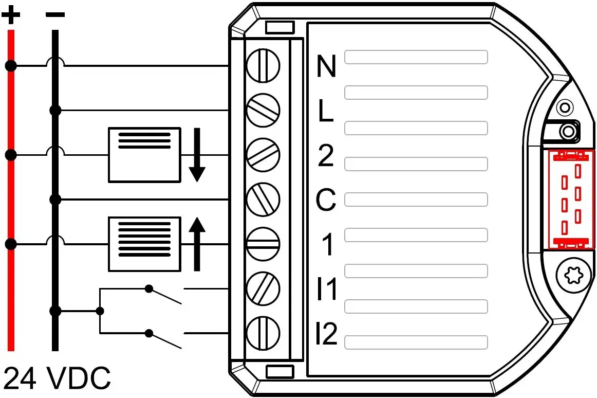
When 110 – 230 VAC is used, press a button connected to input I1 or I2 four times in quick succession to start “Remove”. If a switch is used instead of the button, it must be changed accordingly eight times. Alternatively, when 24 VDC is used, you can press the small lever (T) four times in quick succession with a pen to start “Remove”.
The LED flashes red and then the new status is:
Add: The LED lights up briefly in green
Remove: The LED lights up briefly in red
- For your safety, switch off the mains voltage (break fuse) during installation. Make sure that wires are not short-circuited during and after installation, as this may damage the device.
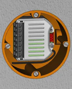
- Connect the cables according to one of the wiring diagrams below. Rigid wires or strands, stripped by about 6.5 mm, can be used for the installation. Option: Connect the device with the ribbon cable to the myTEM Touch Add-on control.
- Check the wiring and then push the device into the flush-mounted box.
- For maximum reach places the antenna upright and as far away from metal parts and the wiring as possible. Attention: Do not shorten the antenna!
- Switch on the mains voltage and include (“Add”) the de- vice into a Z-Wave network as described below.
- Switch off the mains voltage and fit a cover over the flush-mounted box. When you switch the mains voltage back on again is your device ready.
present on the product with a controller providing SmartStart inclusion. No further action is required and the SmartStart product will be added automatically within 10 minutes of being switched on in the network vicinity.
The QR code is located on the side of the housing.
When the device is in the “Add” mode, the LED flashes green. When finished, the new status is:
Add: The LED lights up briefly in green
Remove: The LED lights up briefly in red
Manual inclusion/exclusion (“Add/Remove”)
- Activate the “Add” or “Remove” mode on your controller.
- When 110 – 230 VAC is used, press a button connected to input I1 or I2 four times in quick succession to start to include/exclude (“Add/Remove”). If a switch is used instead of the button, it must be changed accordingly eight times.
- Alternatively, when 24 VDC is used, you can press the small lever (T) four times in quick succession with a pen to start “Add/Remove”.
When the device is in the “Add” mode, the LED flashes green. When finished, the new status is:
Add: The LED lights up briefly in green
Remove: The LED lights up briefly in red
Quick troubleshooting
The following hints may help solve trouble during the network installation.
- Make sure that new devices are in the factory reset state. The status is displayed at power-up.
- If a connection cannot be established, check that the controller and the device are working on the same radio frequency.
- Remove devices that are no longer available in the Z-Wave network from all association groups. Otherwise, significant delays in the execution of commands are possible.
- Make sure you have enough mains-powered devices to benefit from the meshing network.
- If the radio signal is insufficient, try reorienting or relocating the antenna.
Technical specifications
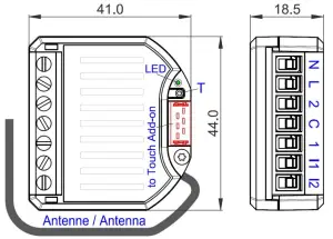
| Dimensions (W × H × D) | 44 × 41 × 18.5 mm | |||
| Installation / mounting | In the flush-mounted box (wall, ceiling) ≥ Ø 60 mm, depth ≥ 60 mm | |||
| Operating voltage | 110 – 230 VAC ± 10%, 50/60Hz or 24 VDC | |||
| Power consumption in standby | Continuous operation for a wireless network, therefore no standby operation | |||
| Power consumption in operation | 0.9 W (including a myTEM Touch Add-on, without consumption of external devices) | |||
| Switchable load | 2× 6 A, 250 VAC or 30 VDC, cos(φ) =1.0 | Connect only one motor, not several in parallel! | ||
| Ambient temperature for operation | 0 °C – 40 °C | |||
| Ambient temperature for storage | -20 °C – 60 °C | |||
| Ambient humidity | 5 %RH – 85 %RH (non condensing) | |||
| Wire cross-section terminals | 0.34 mm² – 6.0 mm² solid; | 0.34 mm² – 4.0 mm² flexible; | 2 × 1.5 mm² two wires | |
| Stripping length for terminals | 6.5 mm ± 0.5 mm | |||
| Tightening torque for terminals | 0.5 Nm | |||
| Degree of protection provided by the enclosure | IP 20 (after installation) | (according to EN 60529) | ||
| Protection class | II | (according to EN 60730-1) | ||
| Overvoltage category | II | (according to EN 60730-1, resp. EN 60664-1) | ||
| Pollution degree | 2 | (according to EN 60730-1) | ||
| Safety main unit | EN 60730-1:2016 + A1:2019 | |||
| EMC main unit | EN 60730-1:2016 + A1:2019 | |||
| EN IEC 61000-6-2:2019 | EN 61000-6-3:2007 + | A1:2011 / AC:2012 | ||
| Safety radio part | EN 62368-1:2014 / AC:2017 | EN 62479:2010 | ||
| EMC radio part | EN 301 489-1 V2.1.1 | EN 301 489-3 V2.1.1 | ||
| Radio spectrum | EN 300 220-2 V3.2.1 | |||
| RoHS | EN IEC 63000:2018 | |||
| CE conformity | 2014/35/EU (LVD) | 2014/53/EU (RED) | ||
| 2014/30/EU (EMC) | 2011/65/EU (RoHS) | |||
| Z-Wave hardware platform | ZM5101 | |||
| Device Type | Window Covering – Endpoint Aware | |||
| Role Type | Always On Slave (AOS) | |||
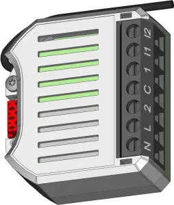
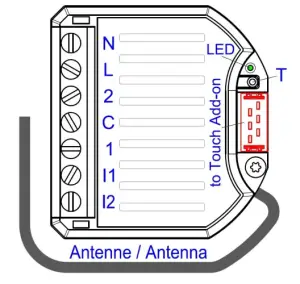
Power supply (Neutral or +24 VDC)
Power supply (Live or 24 VDC ground)
Load output (relay) 2
Load supply (input for relays 1 + 2)
Load output (relay) 1
Input from switch 1 (must have the same potential as terminal L)
Input from switch 2 (must have the same potential as terminal L)
Z-Wave configuration parameters
Z-Wave products can be used out of the box after inclusion (“Add”) into the network. With the configuration, however, the behavior can be better
adapted to the application.
CAUTION! Depending on the function the server may change some default settings.
Par# | Description | Unit | Min | Max | Default | Digits | R/W | Size |
| 1 | Heartbeat rate | min | 1 | 1440 | 60 | 0 | r/w | 2 bytes |
| 2 | Full distance down drive duration | s | 0.00 | 300.00 | — | 2 | r | 2 bytes |
| 3 | Full distance up drive duration | s | 0.00 | 300.00 | — | 2 | r | 2 bytes |
| 4 | Time to move slat between horizontal and vertical | s | 0.00 | 5.00 | 1.20 | 2 | r/w | 2 bytes |
| 5 | Start positioning calibration | – | 0 | 1 | 0 | 0 | r/w | 2 bytes |
| 6 | Invert outputs | – | 0 | 1 | 0 | 0 | r/w | 2 bytes |
| 7 | Min. off time between output on | s | 0.10 | 0.50 | 0.10 | 2 | r/w | 2 bytes |
| 8 | Key assignment local control X) | – | 0 | 6 | 1 | 0 | r/w | 2 bytes |
| 9 | Key hold time to move to end position | s | 0.0 | 5.0 | 2.0 | 1 | r/w | 2 bytes |
X)If a Touch Add-on is connected during inclusion (“Add”), parameter 7 is by default set to 3.
| Values Par# 8 | 0 | 1 | 2 |  | 3 | 4 | 5 | 6 |
| Button Up / Left | Disabled | Shutter – I1 | Shutter – I2 | Touch – T2 | Touch – T3 | Touch – T2 | Touch – T4 | |
| Button Down / Right | Shutter – I2 | Shutter – I1 | Touch – T4 | Touch – T5 | Touch – T3 | Touch – T5 |
Positioning calibration local
The positioning calibration can be activated locally with any key (on I1, I2 or via the Touch Add-on). To do so, briefly tap the selected key twice and hold it for about 1 – 2 seconds. During calibration, the time between the end positions is measured. The process can be aborted by tapping any key once
The blinds, Venetian blinds, shutters, roller shutters, rollers, shades or awnings may be controlled locally. The keys used for the local control are set with parameter #7. Control via local keys can also be deactivated with this parameter.
| Activation of Open or Close button | Action |
| Press the button for a time shorter than the value of parameter # 8 | Movement as long as the button is pressed |
| Press the button for a time longer than the value of parameter # 8 | Moves until end position is reached or movement is stopped |
| Tap 1x on the button during movement | Movement is stopped |
Remote Control – Central Scene Command
Independent whether the local control is activated or not, each keystroke sends a Central Scene command to the controller. Keys are digital inputs 1 – 2 and Touch Add-on buttons 1 – 5.
| Key /Button / Input | Shutter – I1 | Shutter – I2 | Touch – T1 | Touch – T2 | Touch – T3 | Touch – T4 | Touch – T5 |
| Scene number | 1 | 2 | 3 | 4 | 5 | 6 | 7 |
| Action | Hold | Release | Tap 1x | Tap 2x | Tap 3x |
| Central Scene Command | Key Held Down | Key Released | Key pressed 1 time | Key pressed 2 time | Key pressed 3 time |
Use of endpoints 1 and 2
Endpoint 1 is used to set the position of the blind (Multilevel Switch Set) or to start (Multilevel Switch Start Level Change) the movement (without stop until the end position) or to stop it (Multilevel Switch Stop Level Change). When position setting is used (0% is closed, 99% is fully open), the slats are set to the same position as they were at the beginning of the movement.
Endpoint 2 is used to control the angle of the slats (Multilevel Switch Set (0% (0x00) is closed (vertical), 50% (0x32) is open (horizontal)).
Explanation of some Z-Wave specific terms
Controller… is a Z-Wave device with the capability to manage a network. They are typically gateways, remote controls or wall controllers. The primary controller… is the central administrator of the Z-Wave network. In a Z-Wave network, only one primary controller is allowed. Slave… is a Z-Wave device without the ability to manage a network. Slaves can be sensors, actuators, and even remote controls.
Add (Inclusion)… is the process of adding new Z-Wave devices into a network.
Remove (Exclusion)… is the process of removing Z-Wave devices from the network.
Wakeup Notification… is a special wireless message issued by battery-powered Z-Wave devices to announce that they are awake and able to communicate
Node Information Frame (NIF)… is a special wireless message issued by a Z-Wave device to announce its capabilities and functions.
Z-Wave Association – Devices control each other
The Association Command Class is used to manage associations to NodeID destinations. An association group sends commands to the configured destinations when triggered by an event.
Association group of the myTEM Radio Switch Shutter Plus:
Root Device / Endpoint 1 – Window Covering DT, Class B Motor Control
Group ID | Profile / Name | Max. no of units | Command Class | Type / Event | Description |
| 1 | General: Lifeline / Lifeline | 5 | Notification Report | T: System (0x09) E: Heartbeat (0x05) T: Power Management (0x08) E: Power has been applied (0x01) | Reports to be alive (interval according to configuration) Reports the device had a start-up (sent after each power-up only) |
| Central Scene | Key actions remote control | ||||
| Configuration | Full distance down / up drive duration | ||||
| Multilevel Switch | Control of blind position |
The reports “Heartbeat” and “Power Management” can be activated/deactivated separately via the command class Notification.
Endpoint 2 – Window Covering DT, Class B Motor Control:
Group ID | Profile / Name | Max. no of units | Command Class | Description |
| 1 | General: Lifeline / Lifeline | 5 | Multilevel Switch | Control of slats angle of blind |
Supported Command Classes
Root Device / Endpoint 1:
Command Class (CC) | Version | Not added | Non-secure added | Securely added, non-secure CC | Securely added, secure CC |
| Association CC | 2 | Support | Support | Support | |
| Association Group Information CC | 3 | Support | Support | Support | |
| Basic CC | 1 | Support | Support | Support | |
| Central Scene CC | 3 | Support | Support | Support | |
| Configuration CC | 4 | Support | Support | Support | |
| Manufacturer Specific CC | 2 | Support | Support | Support | |
| Multi-Channel Association CC | 3 | Support | Support | Support | |
| Multi-Channel CC | 4 | Support | Support | Support | |
| Multilevel Switch CC | 4 | Support | Support | Support | |
| Powerlevel CC | 1 | Support | Support | Support | |
| Security_2 CC | 1 | Support | Support | Support | |
| Supervision CC | 1 | Support | Support | Support | |
| Transport Service CC | 2 | Support | Support | Support | |
| Version CC | 3 | Support | Support | Support | |
| Z-Wave Plus Info CC | 2 | Support | Support | Support |
Endpoint 2
Command Class (CC) | Version | Non-secure added | Securely added, non-secure CC | Securely added, secure CC |
| Association CC | 2 | Support | Support | |
| Association Group Information CC | 3 | Support | Support | |
| Multi-Channel Association CC | 3 | Support | Support | |
| Security_2 CC | 1 | Support | ||
| Supervision CC | 1 | Support | Support | |
| Z-Wave Plus Info CC | 2 | Support | Support |


