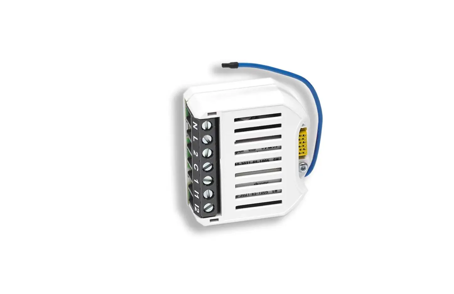
myTEM SmartHome
Radio Switch Shutter Plus
SKU: MTSWIS-101-WL


Quickstart
This is a
secure
Window Covering – Endpoint Aware
for
.
To run this device please connect it to your mains power supply.
Important safety information
Please read this manual carefully. Failure to follow the recommendations in this manual may be dangerous or may violate the law.
The manufacturer, importer, distributor and seller shall not be liable for any loss or damage resulting from failure to comply with the instructions in this manual or any other material.
Use this equipment only for its intended purpose. Follow the disposal instructions.
Do not dispose of electronic equipment or batteries in a fire or near open heat sources.
What is Z-Wave?
Z-Wave is the international wireless protocol for communication in the Smart Home. This
device is suited for use in the region mentioned in the Quickstart section.

Z-Wave ensures a reliable communication by reconfirming every message (two-way
communication) and every mains powered node can act as a repeater for other nodes
(meshed network) in case the receiver is not in direct wireless range of the
transmitter.
This device and every other certified Z-Wave device can be used together with any other
certified Z-Wave device regardless of brand and origin as long as both are suited for the
same frequency range.
If a device supports secure communication it will communicate with other devices
secure as long as this device provides the same or a higher level of security.
Otherwise it will automatically turn into a lower level of security to maintain
backward compatibility.
For more information about Z-Wave technology, devices, white papers etc. please refer
to www.z-wave.info.
Product Description
The myTEM Radio Switch Shutter Plus is a universal, Z-Wave compatible wall or ceiling switch and is used to control the motor of blinds, Venetian blinds, roller shutters, awnings, etc. These are controlled via a myTEM Radio Server, via switches or buttons connected to the inputs or via the optional myTEM Touch Add-on, which can be connected to the rear socket.The device is intended for installation in a flush-mounted box.
Prepare for Installation / Reset
Please read the user manual before installing the product.
In order to include (add) a Z-Wave device to a network it must be in factory default
state. Please make sure to reset the device into factory default. You can do this by
performing an Exclusion operation as described below in the manual. Every Z-Wave
controller is able to perform this operation however it is recommended to use the primary
controller of the previous network to make sure the very device is excluded properly
from this network.
Safety Warning for Mains Powered Devices
ATTENTION: only authorized technicians under consideration of the country-specific
installation guidelines/norms may do works with mains power. Prior to the assembly of
the product, the voltage network has to be switched off and ensured against re-switching.
Inclusion/Exclusion
On factory default the device does not belong to any Z-Wave network. The device needs
to be added to an existing wireless network to communicate with the devices of this network.
This process is called Inclusion.
Devices can also be removed from a network. This process is called Exclusion.
Both processes are initiated by the primary controller of the Z-Wave network. This
controller is turned into exclusion respective inclusion mode. Inclusion and Exclusion is
then performed doing a special manual action right on the device.
Quick trouble shooting
Here are a few hints for network installation if things dont work as expected.
- Make sure a device is in factory reset state before including. In doubt exclude before include.
- If inclusion still fails, check if both devices use the same frequency.
- Remove all dead devices from associations. Otherwise you will see severe delays.
- Never use sleeping battery devices without a central controller.
- Dont poll FLIRS devices.
- Make sure to have enough mains powered device to benefit from the meshing
Association – one device controls an other device
Z-Wave devices control other Z-Wave devices. The relationship between one device
controlling another device is called association. In order to control a different
device, the controlling device needs to maintain a list of devices that will receive
controlling commands. These lists are called association groups and they are always
related to certain events (e.g. button pressed, sensor triggers, …). In case
the event happens all devices stored in the respective association group will
receive the same wireless command wireless command, typically a ‘Basic Set’ Command.
Association Groups:
Group NumberMaximum NodesDescription
| 1 | 5 | Z-Wave Plus LifelineSystem / Heartbeat; sent periodically (see Configuration Parameter Heartbeat)Power Mangement / Power has been applied; sent after Powerup and Reset |
Configuration Parameters
Z-Wave products are supposed to work out of the box after inclusion, however
certain configuration can adapt the function better to user needs or unlock further
enhanced features.
IMPORTANT: Controllers may only allow configuring
signed values. In order to set values in the range 128 … 255 the value sent in
the application shall be the desired value minus 256. For example: To set a
parameter to 200 it may be needed to set a value of 200 minus 256 = minus 56.
In case of a two byte value the same logic applies: Values greater than 32768 may
needed to be given as negative values too.
Parameter 1: Heartbeat rate
A heartbeat notification is sent at this rate
Size: 2 Byte, Default Value: 60
SettingDescription
| 1 – 1440 | Heartbeat rate [min] |
Parameter 2: Full distance down drive time
Time the blind uses to drive from upper end position to the lower end position.
Size: 2 Byte, Default Value: 0
SettingDescription
| 0 – 30000 | Full distance down drive time [0.01s] |
Parameter 3: Full distance up drive time
Time the blind uses to drive from lower end position to the upper end position.
Size: 2 Byte, Default Value: 0
SettingDescription
| 0 – 30000 | Full distance up drive time [0.01s] |
Parameter 4: Time to move slat between horizontal and vertivcal
Time to move slat between horizontal and vertivcal
Size: 2 Byte, Default Value: 120
SettingDescription
| 0 – 500 | Slat move time [0.01s] |
Parameter 5: Start position calibration
Start a positioning calibration. Used to start to measure time used by blind to move from one end position to the other.
Size: 2 Byte, Default Value: 0
SettingDescription
| 0 | Position calibration is inactive / has ended |
| 1 | Start Position calibration / position calibration is active |
Parameter 6: Invert outputs
Normaly output 1 is used to drive blind upwards and output 2 to drive it downwards. When parameter is set to 1 output 1 drives blind downwards and output 2 upwards.
Size: 2 Byte, Default Value: 0
SettingDescription
| 0 | Normal assignment of outputs |
| 1 | Inverted assignment of outputs |
Parameter 7: Min off time of outputs
When blind should change direction while running, the time defined in this parameter is used between stopping active direction output and starting oposite direction output.
Size: 2 Byte, Default Value: 10
SettingDescription
| 10 – 50 | Minimum off time of one output before turning on other one [0.01s] |
Parameter 8: Key assignment local control
Digital inputs and Touch add-on may be used to control blinds locally. Different key pairs can be assigned to control blind to move up or down resp.
Size: 2 Byte, Default Value: 0
SettingDescription
| 0 | Locol control of blinds disabled |
| 1 | Input 1 –> up, input 2 –> down |
| 2 | Input 1 –> down, input 2 –> up |
| 3 | Touch 2 –> up, touch 4 –> down |
| 4 | Touch 3 –> up, touch 5 –> down |
| 5 | Touch 2 –> left, touch 3 –> right |
| 6 | Touch 4 –> left, touch 5 –> right |
Parameter 9: Key hold time to move to end position
When key is hold shorter time than parameter value, movement stops, when key is released. If key is hold longer than parameter value, blind moves until reaching end position also when key is released.
Size: 2 Byte, Default Value: 20
SettingDescription
| 0 – 50 | Key hold time to move to end position [0.1s] |
Technical Data
| Hardware Platform | ZM5101 |
| Device Type | Window Covering – Endpoint Aware |
| Network Operation | Always On Slave |
| Firmware Version | HW: 1 FW: 1.00 |
| Z-Wave Version | 6.82.01 |
| Certification ID | ZC10-21027009 |
| Z-Wave Product Id | 0x034E.0x0001.0x000C |
| Firmware Updatable | Updatable by Consumer by RF |
| Z-Wave Scene Type | Central Scene |
| Electric Load Type | Inductive (e.g. Motor) |
| Supported Notification Types | Power ManagementSystem |
| Security V2 | S2_UNAUTHENTICATED ,S2_AUTHENTICATED |
| Frequency | XXfrequency |
| Maximum transmission power | XXantenna |
Supported Command Classes
- Application Status
- Association Grp Info V3
- Association V2
- Basic
- Central Scene V3
- Configuration V4
- Firmware Update Md V4
- Manufacturer Specific V2
- Multi Channel Association V3
- Multi Channel V4
- Notification V8
- Powerlevel
- Security 2
- Supervision
- Switch Multilevel V4
- Transport Service V2
- Version V3
- Zwaveplus Info V2
Explanation of Z-Wave specific terms
- Controller — is a Z-Wave device with capabilities to manage the network.
Controllers are typically Gateways,Remote Controls or battery operated wall controllers. - Slave — is a Z-Wave device without capabilities to manage the network.
Slaves can be sensors, actuators and even remote controls. - Primary Controller — is the central organizer of the network. It must be
a controller. There can be only one primary controller in a Z-Wave network. - Inclusion — is the process of adding new Z-Wave devices into a network.
- Exclusion — is the process of removing Z-Wave devices from the network.
- Association — is a control relationship between a controlling device and
a controlled device. - Wakeup Notification — is a special wireless message issued by a Z-Wave
device to announces that is able to communicate. - Node Information Frame — is a special wireless message issued by a
Z-Wave device to announce its capabilities and functions.


