
LOCK CHOICE BS-K35 Keypad Access Control
Description
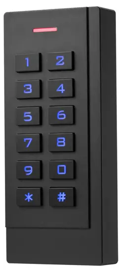
The device is a standalone access control and proximity card reader which supports EM & MF card types. It builds-in STC microprocessor, with strong anti-interference ability,high security and reliability,powerful function and convenient operation. Iiť’s widely used in high-end buildings, residential communities and other public places. 2.
Features
| Ultra-low Power | Standby current is less than 30mA |
| Wiegand Interface | WG26 or WG34 input and output |
| Searching time | Less than 0.1s after reading card |
| Backlight keypad | Operate easily at night |
| Access ways | Card, Pin code, Card & Pin code, APP on the phone. |
| Independent codes | Use codes without related card |
| Change codes | Users can change codes by themselves |
| Delete users by card No. | The lost card can be delete by keyboard |
SPECIFICATIONS
| Working Voltage:DC12-24V | Standby Current:30mA |
| Card Reading Distance:13cm | Capacity:2000 users |
| Working Temperature:-40C60C | Working Humidity:10%90% |
| Lock output load:3A | Door Relay time:099S (Adjustable) |
Installation
Drill hole according to the size of the device and fix the back shell with the equipped screw. Thread the cable through the cable hole. connect the wires according to your required function, and wrap the unused wires to avoid short circuit. After connecting the wire, install the machine. (as show below)
WIRING
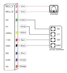
| Color | ID | Description |
| Green | D0 | Wiegand Input(Wiegand Output in Card Reader Mode) |
| White | D1 | Wiegand Input(Wiegand Output in Card Reader Mode) |
| Yellow | OPEN | Exit Button input terminal |
| Red | +12V | 12V + DC Regulated Power Input |
| Black | GND | 12V – DC Regulated Power Input |
| Blue | NO | Relay normally-on terminal |
| Purple | COM | Relay Public terminal |
| Orange | NC | Relay normally-off terminal |
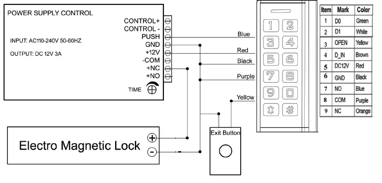
Diagram
Common Power Supply
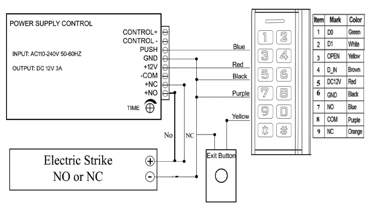
Special Power Supply
Reader Mode
Sound & Light indication
| Operate Status | LED Light Color | Buzzer |
| Standby | Red | |
| Keypad | Beep | |
| Operation Successful | Green | Beep- |
| Operation Failed | Beep-Beep-Beep | |
| Entering into Programming | Flash Red Slowly | Beep- |
| Programmable Status | Orange | |
| Exit Programming | Red | Beep- |
| Door Opening | Green | Beep- |
Advance setting
|
1 | Add Users | Notes | |
| Change Master code | * Master code # 0 New code # New code # | Default factory master code is 999999. | |
| Add card | * Master code # 1 Read card # … # | Cards can be added continuously | |
| Add card number | * Master code # 1 8 digits or 10 digits # | Card number can be added continuously | |
| Add ID number+card | * Master code # 1 ID number # Read card # | Add user with specify ID number, easily find and delete. ID number is from 1-1000 | |
| Add ID number+card number | * Master code # 1 ID number # 8 digits or 10 digits # | Add user with specify ID number, easily find and delete.ID number is from 1-1000 | |
| Add ID number + PIN code | * Master code # 1 ID number # 4 digits Pin code # | ID number is from 1-1000. 4digits Pin coder + # to open | |
|
2 | Delete Users | ||
| Delete card | * Master code # 2 Read card or 8 digits or 10 digits # | Cards can be deleted continuously | |
| Delete ID number | * Master code # 2 ID number # | When the card is broken or lost, you can delete the user by ID number | |
| Delete ALL users | * Master code # 2 0000 # | Delete ALL PIN code & card users except public PIN code. | |
|
3 | Access ways | ||
| By card | * Master code # 3 0 # | Only the card user could unlock the door, keypad is invalid | |
| By card+PIN code | * Master code # 3 1 # | To enable this function, the user PIN code has to be changed. | |
| By card or PIN code | * Master code # 3 2 # | Both card user and PIN user could unlock the door (factory default) | |
| 4 | Relay Output Delay Time | ||||
| Door relay strike time | * Master code # 4 | 0�99 | # | Door opening time range: 0-99s Default 5s | |
|
5 | |||||
| Standalone access control mode | * Master code # 50 # | The door will be locked automatically after open the door normally | |||
| Relay toggle mode | * Master code # 51 # | The door will not be locked automatically.To lock the door, the user has to read the card or press the exit button. | |||
| Reader mode | * Master code # 52 26/34 # | WG26/34 input and output | |||
| 6 | Bind a code to a specific card | * Master code # 6 Read card 4 digits code # | When using card+code to unlock the door | ||
| 7 |
| ||||
|
| |||||
| Wifi matching | * Master code # 73 # | WiFi match, See Wifi instruction manual | |||
| 9 | Add public code | * Master code # 9 4 digits code # | Only one public code is available. Delete public code: * Master code # 9 # | ||
|
* | Change the code by user card | * Read card New code # Repeat new Code # | |||
| Change the code by ID number added | * Old code # New code # Repeat New code # Note: All of codes will be modified except public code. | ||||
| Reset to Factory Default | Power off, press the exit button continuously, power on, hearing beep sound twice, meanwhile, the indicator light turns orange, swipe the first card as for master add card, swipe the second card as for the master delete card, the master code has been reset to 999999, factory default settings are successful. *Registered user data won’t be deleted when reset to factory default | ||||
Master Card Operation


![Schlage Keypad Lock [fe575] User Manual](https://static-data1.manualsee.com/1/img/167/20295/2020/12/Schlage-Keypad-Lock.png "Schlage Keypad Lock [fe575] User Manual")


