![]()
Load Ranger 2.4 GHz RF Quick Start Guide
This document provides the information necessary to quickly set up the Load Ranger wheel weigh pads and pair them with the Ai-1 Indicator to take weight readings.![]() NOTE: For more information, see Load Ranger (RF) Technical Manual (PN 214194).
NOTE: For more information, see Load Ranger (RF) Technical Manual (PN 214194).
Setup Wheel Weigh Pads
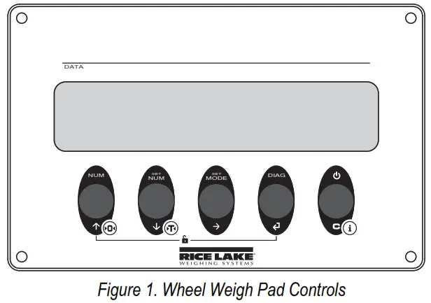
- Press
 to turn on the first wheel weigh pad.
 - Press
 during startup.
  flashes, then
 display.
 - Press until
 displays.
 - Press to
 enter the Serial menu. iD displays.
 - Press to enter the ID settings.
- Press
 or increase or decrease the selected digit and press to move between the digits to enter the pad ID number.
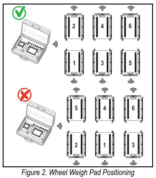
 NOTE: The first Pad ID number must be 01 and the remaining pad ID numbers must increment in ascending numeric order. Example: 01, 02, 03. Do not configure two pads with the same ID number.
- Press. Con.
 displays.
 - Press until
 displays
 - Press.
 displays.
 - Press until unit
 displays.
 - Press.
 chan briefly displays.
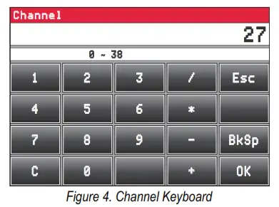
 - Use arrows to enter a channel number.
NOTE: The default channel number is 27. The wheel weighs pad channel number must match the indicator channel number it will pair with. The Ai-1 indicator supports channels 00 – 38. If using multiple groups of indicators and wheel weigh pads, the channel numbers must be unique for each group. - Press.OK briefly displays then Baud displays.
- Press until the wheel weighs pad resets.
- Repeat procedure for all-wheel weighs pads in the system.
Setup Ai-1 Indicator and Pair Wheel Pads
- Turn off all wheel weigh pads.
- Press
 to turn on the Ai-1 indicator.
 - During startup, press the upper right corner of the screen when the logo displays to enter the Technical Setup menu.

- Press
 to go to the second Setup menu page.
 - In the second page, press
 the Serial Port menu displays.
 - Press
 Radio Frequency interface displays.
 - Press

- Enter the required channel numberNOTE: The default channel number is 27. The wheel weighs pad channel number must match the indicator channel number it will pair with. The Ai-1 indicator supports channels 00 – 38. If using multiple groups of indicators and wheel pads, the channel numbers must be unique for each group.

- Press
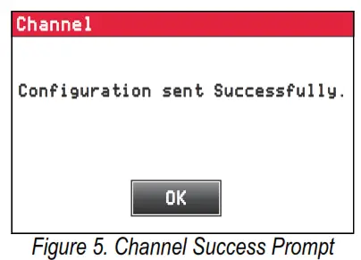
 . A Channel prompt displays.
- . Pressto closes the prompt and returns to the Radio Frequency interface menu.
- Press
 twice.
 - Press

- Press

- Press

- Press
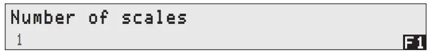
 Number of Scales menu displays.
 - Select the number of wheels to weigh pads to be used.
 Figure 6. Number of Scales Configuration
 - Press
- Ensure all wheel pads have been configured following the steps in section 1, are turned on.
- Press

- Press

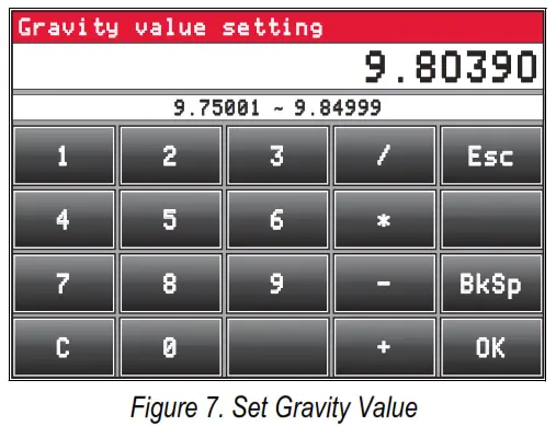
- Gravity value setting pop-up displays.
- Enter the gravity value for the area the wheel weigh pads will be used.

- Pressto close the pop-up and continue.
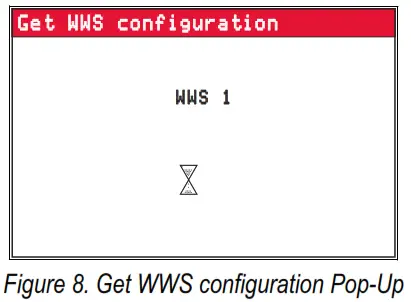
- Get WWS configuration pop-up displays. Wait while configuration information is retrieved from wheel weigh pads.

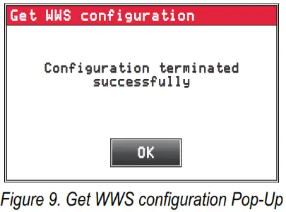
- Once configuration information is retrieved, the configuration session terminates.

- Press o close the pop-up.
- Press

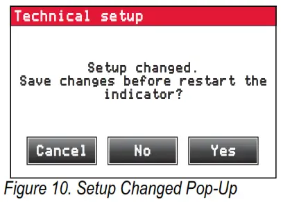
- Setup changed pop-up displays.

- Press
 to save settings and complete setup.
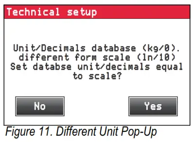
 - (Optional) If indicator and wheel weigh pad units are different, a pop-up may display to update units.

- Press to match units,
 exit Yes without changing.
 - The indicator reboots to Weigh mode.

 the Serial Port menu displays.


 Number of Scales menu displays.
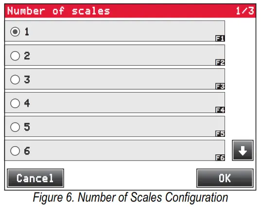 Figure 6. Number of Scales Configuration

Initial Setup Parameters
The following parameter windows may display during the initial setup before the indicator reboots to Weigh mode.
- The Backup of the Configuration window — Press to backup all settings Yes
- The Password window displays — Press or depending on password requirements No
- The Technical Setup window displays — Pressconvert the indicator units to match the wheel weigh pad units
Applications
The Load Ranger wheel weighs pads that can be arranged to serve multiple applications. The adjustment from one scenario to another is made quickly and easily with the wireless and portability features of the Load Ranger system. This section highlights several of the arrangements available.
4.1 Wireless Setup
A wireless system allows for weighing with up to 16 connected wheels and weigh pads per Ai-1 indicator. The wireless system is connected by following sections Section 1. through Section 3. Typically wireless setup is configured for 2, 3, 4,5, or 6 pads.
Two Platform Applications
Two platform applications include weighing axles of the vehicle individually or trailers with only one axle.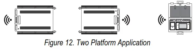 Three Platform Applications
Three platform applications include weighing small planes, three-wheeled vehicles or trailers with a support pin.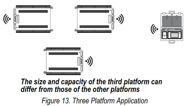 Four Platform Applications
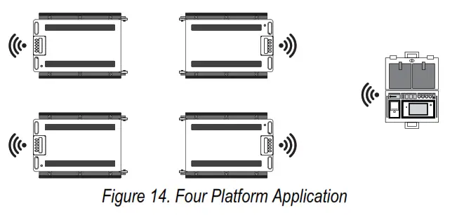
Four platform applications include weighing two-axle vehicles, trailers, containers or other items with four support points.
Five Platform Applications
Five platform applications include weighing two-axle trailers with a support pin. When weighing both directions, a sixth platform can be used.
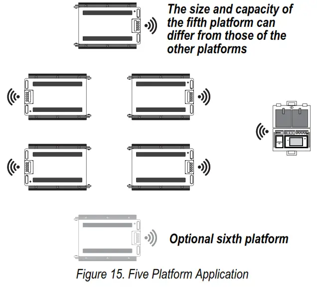
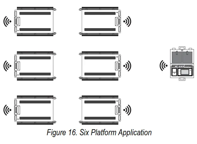
Six Platform Applications
Six platform applications include weighing three-axle vehicles or structures with six support points.
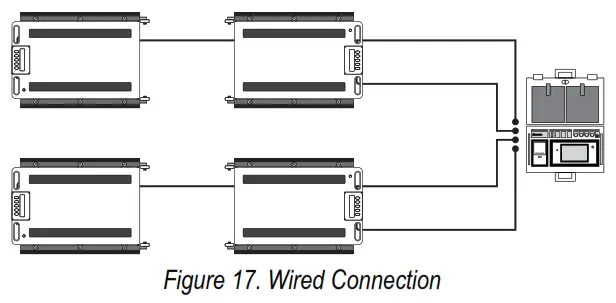
 4.2 Wired Setup
A wired system allows for weighing up to four connected wheels weigh pads.
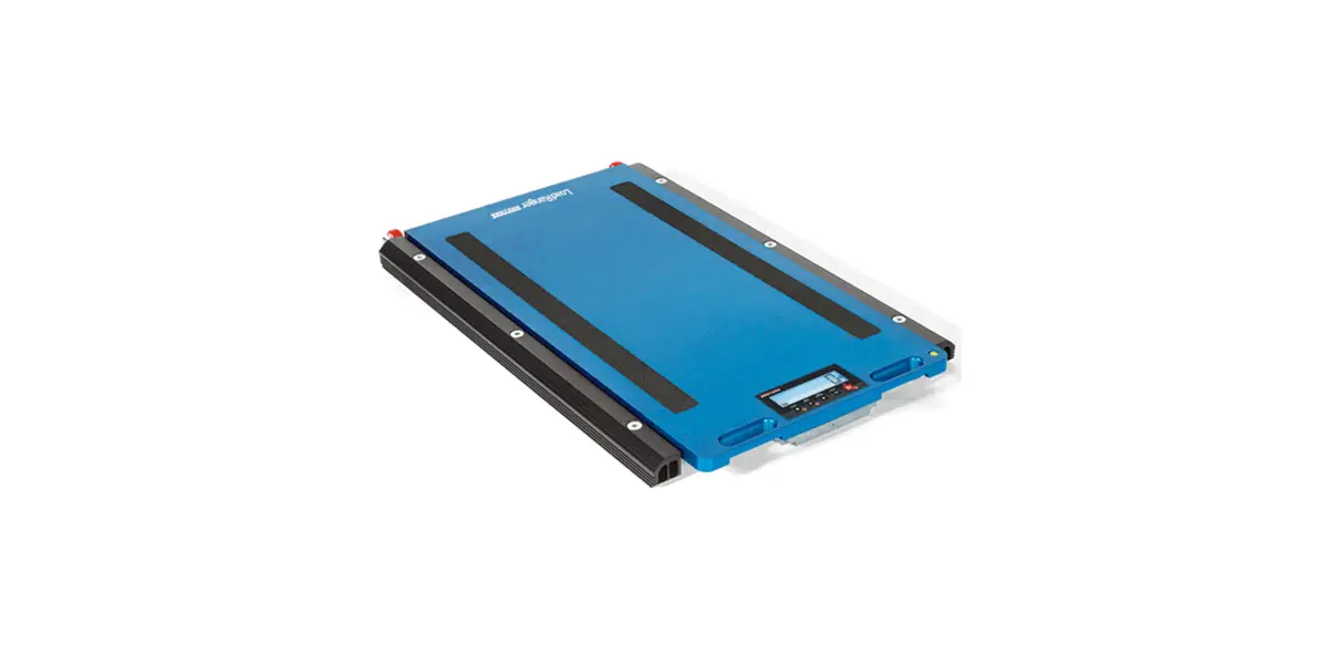
The data communication port is located on the underside of the wheel weigh pad. For the RF-MD, the port is located at the handle end of the platform and is the port further from the edge. For the RF-WD and RF-XWD, the port is located at the end opposite of the platform handles.
4.2.1 Wired Setup Connection Procedure
- Assign channel numbers and ID numbers to the wheel weigh pads.
- Pair the Ai-1 indicator with the wheel weigh pads.
- Turn off the wheel weigh pads and the Ai-1 indicator.
- Connect RS-485 cables to the wheel weigh pads’ data communication ports.
- Connect free ends of each RS-485 cable to one of the Ai-1 indicator’s communication ports.NOTE: The wheel weighs pads can be connected to any of the RS-485 ports on the Ai-1 indicator. The pad ID assigned within the wheel weigh pad dictates the scale
number and it does not need to match the Ai-1 indicator channel number. - Turn on all of the wheels weighs pads.
- Turn on the Ai-1 indicator.
 briefly displays on wheel weigh pads (
 represents the assigned pad ID number)
 . then displays on the wheel weigh pads and they are ready for use.
![]() © Rice Lake Weighing Systems
© Rice Lake Weighing Systems
Content is subject to change without notice.
www.ricelake.com
230 W. Coleman St. • Rice Lake, WI 54868
United States: 800-472-6703
International: +1 715-234-9171
PN 214195 Rev A


