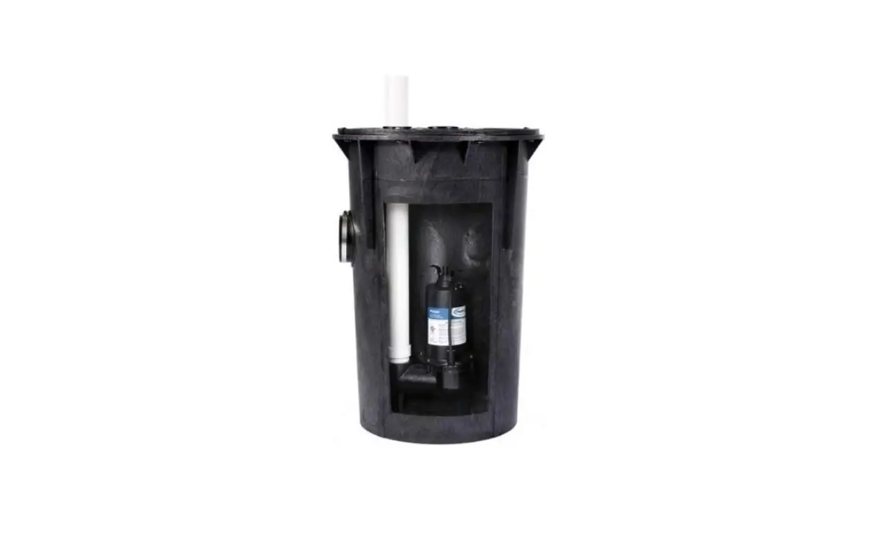
ProFlo Simplex Sewage Pump Kits PF93015 PF93020 Instructions
Safety Guidelines
Carefully read, understand and follow all safety instructions in this manual.
This is the safety alert symbol. When you see this symbol, look for one of the following signal words.
DANGER Indicates a hazardous situation which, if not avoided, will result in death or serious injury.
CAUTION Indicates a hazardous situation which, if not avoided, could result in death or serious injury.
WARNING Indicates a hazardous situation which, if not avoided, could result in minor or moderate injury.
Safety Information
Read these warnings carefully. Know the application and limitations of this pump. Failure to follow these warnings could result in serious bodily injury and/or property damage.
DANGER RISK OF ELECTRICAL SHOCK. Disconnect and lockout power supply before removing old pump or installing or servicing this pump. a DANGER RISK OF ELECTRICAL SHOCK. This pump is supplied with a grounding conductor and grounding type attachment plug. To reduce the risk of electric shock, be certain that it is connected only to a properly grounded, grounding type receptacle. For added safety, it is highly recommended to connect this pump to a GFCI (Ground Fault Circuit Interrupter) outlet. Connect only to a receptacle that is adequately rated for the voltage and amperage of this pump.
WARNING The installation of this pump must be in accordance with the National Electric Code (NEC), Uniform Plumbing Code (UPC), International Plumbing Code (IPC) as well as all applicable local codes and ordinances.
CAUTION Do not install this pump in any location classified as hazardous by the National Electrical Code, ANSI/NFPA70.
CAUTION Do not use this pump to pump flammable or explosive fluids such as gasoline, kerosene, etc. Do not use this pump in flammable or explosive environments. Use only with liquids compatible with pump component materials.
WARNING RISK OF ELECTRICAL SHOCK. This pump has not been investigated for use in swimming pool or marine areas.
WARNING Sewage pumps handle materials that can cause illness or disease. Wear protective clothing when installing or servicing a pump in an existing
WARNING RISK OF ELECTRICAL SHOCK. DO NOT use the power cord to remove or lower the pump into the basin. The cord may pull apart exposing bare wires which could cause a fire or electrical shock. Use the handle supplied with the pump for installing and removing the pump from the basin.
WARNING Do not run the pump dry. This pump relies on water for cooling. Running the pump dry can cause the pump to overheat and the possibility of burns to anyone that handles the pump. Running the pump dry will void the warranty.
WARNING If entry into a septic basin is necessary use proper OSHA safety procedures. Do not enter the basin until those procedures are adhered
WARNING Do not use this pump for potable/drinking water. Use only in applications for which the pump is designed for.
DANGER TO PREVENT RISK OF EXPLOSION. Do not smoke, use flames or electrical devices that could emit sparks in a septic/sewage environment as sewage/septic fumes could be explosive.
WARNING According to the state of California (Prop 65), this product contains chemicals known to the state of California to cause cancer and birth defects or other reproductive harm.
WARNING DO NOT UNDER ANY CIRCUMSTANCES REMOVE THE GROUND PIN. The 3-prong plug must be inserted into a mating 3-prong grounded receptacle. If the installation does not have such a receptacle, it must be changed to the proper type, wired and grounded in accordance with the National Electrical Code and all applicable local codes and ordinances.
WARNING All wiring must be performed by a qualified electrician.
WARNING Keep hands clear of suction & discharge openings. To prevent injury, never insert fingers into pump while it is plugged in.
CAUTION This pump motor is equipped with an automatic resetting thermal protector and may restart unexpectedly.
Specifications
| Model | PF93015 | PF93020 |
| HP | 1/2 | 1/2 |
| Volts | 120 volt AC | 120 volt AC |
| Amps | 7.6 Amps | 7.6 Amps |
| Hz | 60 Hz | 60 Hz |
| Phase | 1 | 1 |
| Circuit Requirements | 15 Amp (min) | 15 Amp (mín) |
| Pump Discharge Size | 2” NPT | 2” NPT |
| Max. Solids Handling | 2” Spherical | 2” Spherical |
| Max. Liquid Temperature | 120°F | 120º F |
| Float Switch Type | Wide angle tethered | Vertical |
| Cut in (Pump on) Level (Factory Set) | 16” | 11” |
| Cut-out (Pump off) Level (Factory Set) | 8” | 4” |
| Cord Length | 10′ | 10′ |
| Pump Construction | Cast Iron | Cast Iron |
| Impeller | Stainless Steel Vortex | Stainless Steel Vortex |
| Motor Shaft | Stainless Steel | Stainless Steel |
| Shaft Seal | Carbon/Ceramic/Stainless Steel | Carbon/Ceramic/Stainless Steel |
| Basin Material | HDPE structural foam | HDPE structural foam |
| Cover Material | HDPE structural foam | HDPE structural foam |
| Cover Gasket | Reusable PVC Seal | Reusable PVC Seal |
| Basin Inlet Size | 4” | 4” |
| Basin Vent & Discharge Size | 2” | 2” |
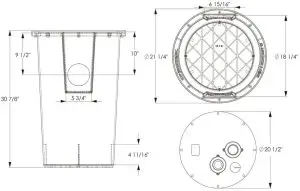
Dimensions
Installation Piping & Basin
Piping must not be smaller than the pump discharge, in this case 2″. The pipe must be capable passing solids of at least 2″ in diameter. To meet minimum flow requirements, size the pipe as follows.
| A pipe size of | Will Handle a Flow Rate of |
| 2″ | 21 GPM |
| 2-1/2″ | 30 GPM |
| 3″ | 48 GPM |
- Before installation, check the pump and pipe inside the basin for damage that may have occurred during shipping.
- Dig a hole for the basin (if necessary). The hole should be approximately 24″ larger in diameter and 12″ deeper than the basin size to provide adequate room for the sub-base & backfill. Backfill and sub-base should be 1/8″ to 3/4″ pea gravel or crushed stone.
- Install the basin on top of the sub-base making sure the basin is level. If necessary, level the top of the basin level with the finished floor.
- Insert the 4″ inlet pipe through the inlet hub.
NOTE: To aid in installation, use liquid soap to lubricate the pipe and hub. Bevel or file the sharp edges of the pipe to prevent damage to the hub. Insert the pipe approximately 2″ into the basin and secure by tightening the stainless steel clamp. The pipe should pitch downward to the basin by approximately 1/4″ per foot to allow water to run into the basin. - Backfill around the basin with crushed stone or pea gravel.
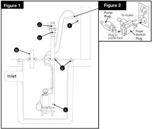
A. 3/16″ Anti-airlock hole
B. Vent basin in accordance with applicable codes
C. Ball or gate valve (sold separate
D. Check valve / union combination (sold separately)
E. Liquid & gas tight seals
F. Electrical supply must be in accordance with the National Electric Code and/or other applicable codes.
- Install a 2″ vent pipe into the 2″ NPT threaded vent flange (B). Connect the vent pipe to the existing vent pipe or run the pipe through the roof of the building. The sewage basin MUST be vented in accordance with all local codes.
- Install a 2″ full flow check valve (C) (sold separately) onto the discharge pipe to prevent backflow into the basin. The check valve should be a full flow type and be capable of handling 2″ solids. Install the check valve with the flow direction arrow pointing in the direction of flow. For best performance, do not install the check valve more that 45° above the horizontal as solids may accumulate in the valve and prevent it from opening upon pump startup. It is recommended to use a union and check valve/ball valve combination to allow for easy removal of the pump. Install per the check valve manufacturer’s installation instructions.
- Connect the remaining discharge pipe from the check valve / ball valve to the septic tank, sewage line, etc., using the shortest length of pipe and fewest number of turns as possible.
Alarm
The use of an alarm (sold separately) is recommended to warn of a high-water condition resulting from pump and/or control malfunction. The power supply for the alarm should be on a separate circuit so that a circuit interruption to the pump will not affect the alarm circuit.
Operation
- Plug the piggy-back plug of the float switch into a 120 volt grounded outlet. See Figure 2
- The use of a GFCI is strongly recommended. Plug the pump plug into the back of the piggy-back float switch plug.
NOTE: If connecting the pump and float switch to a control panel, follow the manufacturers instructions for proper installation 2. Check the installation by filling the basin and observing the pump operation through several complete cycles. Make any necessary adjustments at this time.
Maintenance
DANGER Risk of electric shock. Always disconnect the power supply before attempting to install, service or perform maintenance on the pump.
WARNING All repairs must be made by an authorized service center.
CAUTION This submersible pump contains oil which may become pressurized and hot under normal operating conditions – allow the pump to cool for 2-3 hours before servicing.
- Periodically inspect and clean the anti-airlock hole.
- Inspect the float switch for any accumulated debris that may inhibit it from operating properly. Clean if necessary.
- The pump has sealed, permanently lubricated bearings and require no additional lubrication.
- In applications where the pump may not activate for extended periods of time, it is recommended to cycle the pump at least once per month to ensure the pumping system is working properly when needed.
Performances
Height and/or piping restriction will reduce the pump output performance. It is recommended to use the same size or larger pipe as the pump discharge for optimum performance.
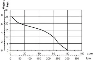
Discharge Height | 0′ | 5′ | 10′ | 15′ | 20′ | 25′ |
| Gallons Per Minute | 80 | 68 | 60 | 44 | 13 | 2 |
Troubleshooting
| Problem | Possible Causes | How to Correct |
| If the pump does not start or run | Pump is not plugged in, switch or breake is turned off | Plug pump in or turn on switch/breaker |
| Check for blown fuses or tripped circuit breakers or tripped GFCI outlets | Replace fuse, reset breaker, reset GFCI outlet | |
| Float switch is defective | Check and replace if necessary | |
| Motor thermal protector tripped | Allow pump to cool. Pump will reset automatically | |
| Float switch is stuck or obstructed | Remove obstruction or position pump so it will not become stuck | |
| The pump cycles too frequently or runs periodically when fixtures are not in use. | Backflow of water from discharge pipe | Install or replace check valve |
| Float switch is defective | Replace float switch | |
| Fixtures are leaking | Repair Fixtures to eliminate leakage | |
| If the pump runs but moves little or no water | Obstructed discharge hose/pipe | Remove obstruction |
| Frozen discharge hose/pipe | Allow hose/pipe to thaw | |
| Pump is air locked | Remove | |
| Low line voltage | Check wire size and increase if necessary | |
| Check valve is stuck in the closed position or defective | Inspect, repair or replace if necessary | |
| Check valve is installed backwards | Make sure valve is installed in the correct direction of flow | |
| Worn, damaged or clogged pump parts | Inspect for wear, damage or clog and clean or replace part if necessary | |
| Discharge head exceeds pump capacity | If pumping height is over 25′, the pump will not move water. See performance chart | |
| Pump does not shut off | Float switch is obstructed or stuck | Remove obstruction |
| Defective Float Switch | Replace float switch |
Repayment Parts
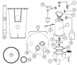
| Ref# | Part # Description PF93015 | Part # PF93020 | |
| 1 2 | Power Cord | 99108 | 99108 |
| Pump Handle | 99053 | 99053 | |
| 3 4 | Oil Fill Plug (Includes 0-ring) | 99056 | 99056 |
| Shaft Seal | 99057 | 99057 | |
| 5 | Impeller (Includes nut & washer) | 99095 | 99095 |
| 6 | Gasket | 99091 | 99091 |
| 7 | S Volute | 99097 | 99097 |
| 8 | Float Switch (92010 includes float switch, float rod, float ball and grommet) | 92000 | 92010 |
| 9 | 18″ x 30″ Structural Foam Basin | 99275 | 99275 |
| 10 | 4″ Inlet Hub | 99277 | 99277 |
| 11 | Cover (Includes PVC seal, vent & discharge flanges, cord grommet & bolts) | 99276 | 99276 |
| 12 | 2″ Threaded Vent Flange (Includes 0-ring) | 99284 | 99284 |
| 13 | 2″ Discharge Flange (Includes 0-ring) | 99282 | 99282 |
| 14 | PVC Seal | 99285 | 99285 |
| 15 | Cord Grommet | 99278 | 99278 |
| 16 | 1/4″ x 1″ Stainless steel bolts for cover (qty 8) | 99280 | 99280 |
| 17 | Stainless Steel Nut & Washer (M6) | 99164 | 99164 |
| 18 | Vertical Float Switch Bracket | n/a | 99105 |
| 19 | Float Switch Ball | 99170 | 99170 |
| 20 | 2″ PVC Male Adapter | 99540 | 99540 |
| 21 | 2″ PVC Pipe – 30″ Long | 99542 | 99542 |
Warranty
LIMITED WARRANTY – SIMPLEX SEWAGE PUMP KITS:
Manufacturer warrants the products specified in this warranty to be free from defects in material or workmanship for three (3) years from date of purchase. During the time period and subject to the terms and conditions, the manufacturer will repair or replace to the original user or consumer any portion of this product which proves to be defective due to materials or workmanship. At all times the manufacturer shall have and possess the sole right and option to determine whether to repair or replace defective equipment, parts, or components. The manufacturer has the option to inspect any product returned under warranty to confirm that the warranty applies before repair or replacement under warranty is approved. This warranty sets forth the manufacturer’s sole obligation and purchaser’s exclusive remedy for defective product. Return defective product to the place of purchase for warranty consideration.
WARRANTY PERIOD – PRODUCTS:
If, within the duration of product use by the original user, this product proves to be defective due to materials or workmanship, the product shall be repaired or replaced at the manufacturer’s option, subject to the terms and conditions set forth in this warranty statement. Proof of purchase is required for warranty consideration. In the absence of suitable proof of the purchase date, the effective period of this warranty is 12 months from the product’s date of manufacture.
LABOR, ETC. COSTS:
The manufacturer shall IN NO EVENT be responsible or liable for the cost of field labor or other charges incurred by any customer in removing and/or affixing any product, part, or component thereof.
PRODUCT IMPROVEMENTS:
The manufacturer reserves the right to change or improve its products or any portions thereof without being obligated to provide such a change or improvement for units sold and/or shipped prior to such change or improvement.
GENERAL TERMS AND CONDITIONS:
This warranty shall not apply to damage due to acts of God, normal wear and tear, normal maintenance services and the parts used in connection with such service, lightning or conditions beyond the control of the manufacturer, nor shall it apply to products which, in the sole judgment of the manufacturer, have been subject to negligence, abuse, accident, misapplication, tampering, alteration; nor due to improper installation, operation, maintenance or storage; nor to excess of recommended maximums as set forth in the instructions. Warranty will be VOID if any of the following conditions are found:
- Product is used for purposes other than those for which it was designed and manufactured
- Product not installed in accordance with applicable codes, ordinances, and good trade practices
- Product connected to voltage other than indicated on nameplate or labels
- Pump exposed to but not limited to the following: sand, gravel, cement, grease, plaster, mud, tar, oil, gasoline, solvents or other abrasive or corrosive substances
- Pump has been used for pumping liquids above 120°F 6. Pump allowed to operate dry (liquid supply cut off)
DISCLAIMER:
Any oral statements about the product made by the seller, the manufacturer, the representatives, or any other parties do not constitute warranties, shall not be relied upon by the user, and are not part of the contract for sale. Seller’s and the manufacturers only obligation, and buyer’s only remedy, shall be the replacement and/or repair by the manufacturer of the product as described above. NEITHER SELLER NOR THE MANUFACTURER SHALL BE LIABLE FOR ANY INJURY, LOSS OR DAMAGE, DIRECT, INCIDENTAL OR CONSEQUENTIAL (INCLUDING, BUT NOT LIMITED TO, INCIDENTAL OR CONSEQUENTIAL DAMAGES FOR LOST PROFITS, LOST SALES, INJURY TO PERSON OR PROPERTY, OR ANY OTHER INCIDENTAL OR CONSEQUENTIAL LOSS), ARISING OUT OF THE USE OR THE INABILITY TO USE THE PRODUCT, AND THE USER AGREES THAT NO OTHER REMEDY SHALL BE AVAILABLE TO IT. Before using, the user shall determine the suitability of the product for his/her intended use, and user assumes all risk and liability whatsoever in connection therewith.
THE WARRANTY AND REMEDY DESCRIBED IN THIS LIMITED WARRANTY IS AN EXCLUSIVE WARRANTY AND REMEDY AND IS IN LIEU OF ANY OTHER WARRANTY OR REMEDY, EXPRESSED OR IMPLIED, WHICH OTHER WARRANTIES AND REMEDIES ARE HEREBY EXPRESSLY EXCLUDED, INCLUDING BUT NOT LIMITED TO ANY IMPLIED WARRANTY OF MERCHANTABILITY OR FITNESS FOR A PARTICULAR PURPOSE, TO THE EXTENT EITHER APPLIES TO A PRODUCT SHALL BE LIMITED IN DURATION TO THE PERIODS OF THE EXPRESSED WARRANTIES GIVEN ABOVE.
Some states and countries do not allow the exclusion or limitations on how long an implied warranty lasts or the exclusion or limitation of incidental or consequential damages, so the above exclusion or limitations may not apply to you. This warranty gives you specific legal rights, and you may also have other rights which vary from state to state.


