![]()
INSTALLATION &
OPERATION MANUAL
EMERGENCY BACKUP
SUMP PUMP SYSTEM
Models:
PF92952,PF92941
Safety Guidelines
Carefully read, understand and follow all safety instructions in this manual.![]() This is the safety alert symbol. When you see this symbol, look for one of the following signal words.
This is the safety alert symbol. When you see this symbol, look for one of the following signal words.![]() DANGER Indicates a hazardous situation that, if not avoided, will result in death or serious injury.
DANGER Indicates a hazardous situation that, if not avoided, will result in death or serious injury.![]() CAUTION Indicates a hazardous situation that, if not avoided, could result in death or serious injury.
CAUTION Indicates a hazardous situation that, if not avoided, could result in death or serious injury.![]() WARNING Indicates a hazardous situation that, if not avoided, could result in minor or moderate injury.
WARNING Indicates a hazardous situation that, if not avoided, could result in minor or moderate injury.
Safety Information
Read these warnings carefully. Know the application and limitations of this pump. Failure to follow these warnings could result in serious bodily injury and/or property damage.![]() DANGER RISK OF ELECTRICAL SHOCK. Disconnect and lockout power supply before removing old pump or installing or servicing this pump.
DANGER RISK OF ELECTRICAL SHOCK. Disconnect and lockout power supply before removing old pump or installing or servicing this pump.![]() DANGER RISK OF ELECTRICAL SHOCK. This pump is supplied with a grounding conductor and grounding-type attachment plug. To reduce the risk of electric shock, be certain that it is connected only to a properly grounded, grounding-type receptacle. For added safety, it is highly recommended to connect this pump to a GFCI (Ground Fault Circuit Interrupter) outlet. Connect only to a receptacle that is adequately rated for the voltage and amperage of this pump
DANGER RISK OF ELECTRICAL SHOCK. This pump is supplied with a grounding conductor and grounding-type attachment plug. To reduce the risk of electric shock, be certain that it is connected only to a properly grounded, grounding-type receptacle. For added safety, it is highly recommended to connect this pump to a GFCI (Ground Fault Circuit Interrupter) outlet. Connect only to a receptacle that is adequately rated for the voltage and amperage of this pump
![]() WARNING The installation of this pump must be in accordance with the National Electric Code (NEC), Uniform Plumbing Code (UPC), International Plumbing Code (IPC) as well as all applicable local codes and ordinances.
WARNING The installation of this pump must be in accordance with the National Electric Code (NEC), Uniform Plumbing Code (UPC), International Plumbing Code (IPC) as well as all applicable local codes and ordinances.![]() CAUTION Do not install this pump in any location classified as hazardous by the National Electrical Code, ANSI/NFPA70.
CAUTION Do not install this pump in any location classified as hazardous by the National Electrical Code, ANSI/NFPA70.![]() CAUTION Do not use this pump to pump flammable or explosive fluids such as gasoline, kerosene, etc. Do not use this pump inflammable or explosive environments. Use only with liquids compatible with pump component materials.
CAUTION Do not use this pump to pump flammable or explosive fluids such as gasoline, kerosene, etc. Do not use this pump inflammable or explosive environments. Use only with liquids compatible with pump component materials.![]() WARNING RISK OF ELECTRICAL SHOCK. This pump has not been investigated for use in swimming pools or marine areas.
WARNING RISK OF ELECTRICAL SHOCK. This pump has not been investigated for use in swimming pools or marine areas.![]() WARNING RISK OF ELECTRICAL SHOCK. DO NOT use the power cord to remove or lower the pump into the basin. The cord may pull apart exposing bare wires which could cause a fire or electrical shock. Use the handle supplied with the pump for installing and removing the pump from the basin.
WARNING RISK OF ELECTRICAL SHOCK. DO NOT use the power cord to remove or lower the pump into the basin. The cord may pull apart exposing bare wires which could cause a fire or electrical shock. Use the handle supplied with the pump for installing and removing the pump from the basin.![]() WARNING Do not run the pump dry. This pump relies on water for cooling. Running the pump dry can cause the pump to overheat and the possibility of burns to anyone that handles the pump. Running the pump dry will void the warranty.
WARNING Do not run the pump dry. This pump relies on water for cooling. Running the pump dry can cause the pump to overheat and the possibility of burns to anyone that handles the pump. Running the pump dry will void the warranty.![]() WARNING Don’t expose the pump to freezing temperatures. Discharge lines exposed to freezing temperatures should be positioned with a downward slope to prevent freezing.
WARNING Don’t expose the pump to freezing temperatures. Discharge lines exposed to freezing temperatures should be positioned with a downward slope to prevent freezing.
Safety Information (continued)
![]() WARNING Do not use this pump for potable/drinking water. Use only in applications for which the pump is designed.
WARNING Do not use this pump for potable/drinking water. Use only in applications for which the pump is designed.![]() WARNING According to the state of California (Prop 65), this product contains chemicals known to the state of California to cause cancer and birth defects, or other reproductive harm.
WARNING According to the state of California (Prop 65), this product contains chemicals known to the state of California to cause cancer and birth defects, or other reproductive harm.![]() WARNING DOES NOT UNDER ANY CIRCUMSTANCES REMOVE THE GROUND PIN. The 3-prong plug must be inserted into a mating 3-prong grounded receptacle. If the installation does not have such a receptacle, it must be changed to the proper type, wired, and grounded in accordance with the National Electrical Code and all applicable local codes and ordinances.
WARNING DOES NOT UNDER ANY CIRCUMSTANCES REMOVE THE GROUND PIN. The 3-prong plug must be inserted into a mating 3-prong grounded receptacle. If the installation does not have such a receptacle, it must be changed to the proper type, wired, and grounded in accordance with the National Electrical Code and all applicable local codes and ordinances.![]() WARNING All wiring must be performed by a qualified electrician.
WARNING All wiring must be performed by a qualified electrician.![]() WARNING Keep hands clear of suction & discharge openings. To prevent injury, never insert fingers into the pump while it is plugged in.
WARNING Keep hands clear of suction & discharge openings. To prevent injury, never insert fingers into the pump while it is plugged in.![]() WARNING Sump basins must be vented according to local plumbing codes. Do not handle this pump with wet hands or while standing on wet or damp surfaces or in water.
WARNING Sump basins must be vented according to local plumbing codes. Do not handle this pump with wet hands or while standing on wet or damp surfaces or in water.![]() WARNING If a flexible discharge hose is used, make sure the pump is secured in the basin to prevent movement. Failure to secure the pump could result in flooding from switch malfunction.
WARNING If a flexible discharge hose is used, make sure the pump is secured in the basin to prevent movement. Failure to secure the pump could result in flooding from switch malfunction.
![]() CAUTION This pump motor is equipped with an automatic resetting thermal protector and may restart unexpectedly.
CAUTION This pump motor is equipped with an automatic resetting thermal protector and may restart unexpectedly.![]() DANGER Never touch any electrical device, including this pump and charger, when it is touching the water, in water, or even in a moist environment. Always unplug (disconnect the electricity) when working on or installing the unit.
DANGER Never touch any electrical device, including this pump and charger, when it is touching the water, in water, or even in a moist environment. Always unplug (disconnect the electricity) when working on or installing the unit.![]() DANGER RISK OF ELECTRICAL SHOCK. Do not plug in or unplug the AC transformer while standing on a wet floor. If the basement floor is wet, disconnect the power before walking on the floor.
DANGER RISK OF ELECTRICAL SHOCK. Do not plug in or unplug the AC transformer while standing on a wet floor. If the basement floor is wet, disconnect the power before walking on the floor.![]() CAUTION Battery acid is corrosive. Do not spill on skin, clothing, or parts of this system. Wear gloves and eye protection when handling the battery.
CAUTION Battery acid is corrosive. Do not spill on skin, clothing, or parts of this system. Wear gloves and eye protection when handling the battery.![]() CAUTION This product can expose you to chemicals including vinyl chloride which is known to the state of California to cause cancer. For more information go to www.P65Wa nings.ca.gov
CAUTION This product can expose you to chemicals including vinyl chloride which is known to the state of California to cause cancer. For more information go to www.P65Wa nings.ca.gov
Description
This primary/battery backup pump system is designed to remove water from residential sump basins. The all-in-one kit is pre-assembled for easy installation and includes a 1/3 HP primary pump and a 12-volt backup pump. Each pump has a vertical float switch and a 10′ power cord.
Specifications
Model Primary Pump | Pum Primary Pump PF92341 | 12 Volt Backup pump PF92910 | |
| HP | 1/3 | 1/3 | n/a |
| Volts | 120 volt AC | 120 volt AC | 12 volt DC |
| Amps | 5.9 Amps | 4.1 Amps | 12 Amps |
| Hz | 60 Hz | 60 Hz | n/a |
| Phase | 1 | 1 | n/a |
| Discharge Size | 1-1/2″ FNPT | 1-1/2″ FNPT | 1-1/4′ or 1/2″ NPT |
| Max. Solids Handling | 1/2″ | 3/8′ | 1/8″ |
| Liquid Temperature Range | 32°F – 120°F | 32°F – 120°F | 32°F – 120°F |
| Cord Length | 10′ | 10′ | 10′ |
| Switch Type | Vertical | Vertical | Vertical |
| Switch on Level (Factory Set) | 8.5″ | 6″ | 10′ |
| Switch off Level (Factory Set) | 3″ | 2″ | 8′ |
| Pump Housing Construction | Cast Iron | Cast Iron | Thermoplastic |
| Pump Base Construction | Cast Iron | Cast Iron | Thermoplastic |
| Impeller | Thermoplastic | Stainless Steel | Thermoplastic |
| Motor Shaft | Stainless Steel | Stainless Steel | Stainless Steel |
| Shaft Seal | Carbon/Ceramic/ Stainless Steel | Carbon/Ceramic/ Stainless Steel | Carbon/Ceramic/ Stainless Steel |
| Fasteners | Stainless Steel | Stainless Steel | Stainless Steel |
| Shut off head | 26′ | 26′ | 21′ |
| Max. PSI | 10.8 | 10.8 | 9.0 |
| Battery Charger | n/a | n/a | 2 Amp |
| Low Voltage Cutoff | n/a | n/a | .10.8 Volts |
Battery Selection
This backup pump in this system is designed to work with 12 volt, lead-acid, deep cycle marine/RV, and AGM batteries. Either a flooded cell (serviceable or maintenance-free) or sealed AGM battery is acceptable. It is recommended to choose a battery with a minimum 40 amp-hour rating. The higher the amp-hour rating on the battery, the longer the pump will run on battery power. Avoid using automobile batteries as these types of batteries are not intended to be charged/discharged for extended periods of time.
The battery case will accommodate group 24 or 27 batteries.
During prolonged periods of power failure or in an emergency situation, your automobile battery may be used Make sure to replace the deep cycle battery as soon as possible as the automobile battery will be quickly damaged by the continuous charge/discharge cycles. Carbon Monoxide (CO) Detectors
All backup pump systems that use lead-acid batteries, regardless of brand, give off gaseous by-products when the battery is charging. Some of these by-products can cause a carbon monoxide (CO) detector to give a false alarm. When installing this system, position the battery as far away from the CO detector as possible. DO NOT move or remove CO detectors from their original location. Always follow the instructions that accompany your CO detector.
If your CO detector alarm sounds, take the following actions.
- Take immediate action for personal safety as outlined in the CO detector manual.
Contact the appropriate utility agency to determine if the CO is coming from your furnace, water heater, or other appliance that uses natural gas
If it’s determined that a charging battery (sold separately) is causing the CO detector to activate, contact the battery manufacturer for recommendations on how to alleviate the problem.
Installation
- This primary/backup pump kit comes completely assembled. To install, simply place the pump assembly in the bottom of your basin and connect it to your new or existing discharge pipe. The pump should be placed on a solid foundation. Do not place the pump directly on the ground or on sandy or rocky surfaces. Sand and small stones may clog or cause damage to your pump.
- Install this pump making sure that the float switches will operate freely without coming in contact with the sides of the sump basin. Contact with the side of the sump basin may cause the switch to malfunction. See figure below.
 |  |
Installation
Electrical Connections
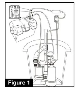
- If necessary, attach the provided battery terminals to the battery (battery is sold separately). Many deep cycle marine & AGM batteries come with a threaded post terminal built-in. NOTE The provided battery terminals are labeled (+) positive and (-) negative. Make sure the terminals are connected to the proper terminal on the battery. Place the battery in the battery box.
- Connect the battery lead wires from the control panel to the corresponding terminals on the battery. Connect the red (+) positive lead to the positive battery terminal and securely tighten the nut. Connect the black (-) negative lead to the negative battery terminal and securely tighten the nut. Secure the battery box cover to the lower case.
- Connect the 12-volt pump power cord to the corresponding receptacle on the control panel. Make sure it is fully seated in the receptacle.
- Connect the 12-volt pump float switch plug to the corresponding receptacle on the control panel. Make sure it is fully seated in the receptacle.
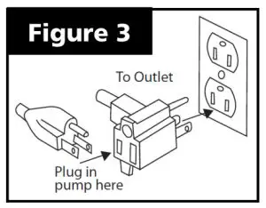
- Connect the control panel power cord to the side of the control panel. Make sure it is fully seated in the receptacle. Plug the power cord into the outlet.
- Plug the primary pump float switch plug into a grounded outlet. Next, plug the primary pump plug into the piggyback plug of the float switch.
- Test the float switch and pump by lifting and holding the float. The alarm will sound and the “PUMP ACTIVATION” light on the control panel will illuminate. The “SYSTEM’ light will also change from green to red. The pump should start after lifting the float. If it does not run, check your connections and retry.
- Test the “MUTE” button when the alarm is sounding. Press once to mute the alarm, or press and hold for 5 seconds to silence the alarm.
NOTE: When silencing the alarm press and hold the “MUTE/SILENCE” button until it beeps (approximately 5-6 seconds). This will indicate that the alarm is silenced To re-activate the alarm, press and hold the TEST/RESET button until it beeps.
9. Secure the float switch and pump cords to the discharge pipe using the provided zip ties. This is to prevent the cords from obstructing the float switches during operation.
Installation – Testing installation
- Once your installation and wiring connections are complete, unplug or disconnect the power to the primary pump.
- Fill the basin using buckets or a hose. Observe the float switches to make sure they are positioned properly when the basin is filling. Fill the basin until the backup float activates the alarm. The pump should start and drain the basin
- Make any necessary adjustments to the float(s) and/or pumps at this time.
Operation
- When the power fails or when there is a problem with the primary pump, the backup pump will automatically start. The backup pump will operate for many hours intermittently on battery power. During prolonged periods of a power outage, the pump may stop pumping when the battery voltage drops below 10.8 volts. When this happens the alarm will sound Signaling that the voltage is too low to operate the pump.
- This unit is equipped with a 2 amp charger. It will charge a discharged battery at a rate of 2 Ah (Amp-hours). Once the battery reaches a full charge, the charger will gradually reduce the charge rate. It will also maintain a charged battery by periodically checking the voltage of the battery.
- The charger is equipped with overcharge protection. It will not let the battery become overcharged.
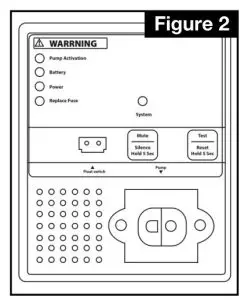
WARNING LIGHTS & CONTROLS
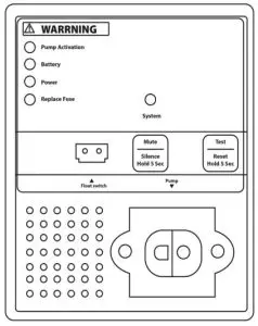
System – When the system is operating normally without any warnings or notifications, this light will illuminate solid green. Pump Activation – This light will illuminate and the alarm will sound when the backup pump has activated. Press and hold the test/reset for 5 seconds (until it beeps) to re-set.
Battery – This light will illuminate and the alarm will sound when the battery voltage drops below 10.8 volts. Press and hold the Test/Reset button (until it beeps) for 5 seconds to reset. Power – This light will illuminate and the alarm will sound when the AC power to the control panel is interrupted or disconnected. This would indicate a loose or disconnected power cord, a power outage, or a blown fuse/circuit breaker, or tripped GFCI outlet. Press and hold the Test/Reset button for 5 seconds (until it beeps) to reset.
Replace Fuse – This light will illuminate and the alarm will sound when the fuse is blown and needs to be replaced. Press and hold the Test/Reset button for 5 seconds (until it beeps) to reset.
Mute / Silence – Press this button once to mute the alarm. The alarm will remain muted until another warning is detected. Press and hold this button for 5 seconds until it beeps to permanently silence the alarm. To reactivate the alarm, press and hold the Test/Reset button for 5 seconds (until it beeps).
Test/Reset – Press this button once to test the status of the control panel and the operation of the backup pump. The green light will flash and the pump will operate for approximately 5 seconds and turn off. If any problems are detected, the alarm will sound and the corresponding light will illuminate. Press and hold this button for 5 seconds (until it beeps) to reset all alarm & warning notifications.
Maintenance
![]() DANGER Risk of electric shock. Always disconnect the power supply before attempting to install, service, or perform maintenance on the pump.
DANGER Risk of electric shock. Always disconnect the power supply before attempting to install, service, or perform maintenance on the pump.![]() WARNING All repairs must be made by an authorized service center.
WARNING All repairs must be made by an authorized service center.![]() CAUTION The primary sump pump contains oil that may become pressurized and hot under normal operating conditions – allow the pump to cool for 2-3 hours before serving.
CAUTION The primary sump pump contains oil that may become pressurized and hot under normal operating conditions – allow the pump to cool for 2-3 hours before serving.
1. The pump motor is hermetically sealed in the housing and does not require any service. Disassembly of the motor housing or modification of the power cord voids the warranty.
2. Periodically check the sump basin for the accumulation of mud, silt, sand, and foreign objects. Clean the basin as needed to prevent damage or clogging of the pump.
3. Periodically inspect and clean the anti-airlock hole.
4. Inspect the float switch for any accumulated debris that may inhibit it from operating properly. Clean if necessary.
5. In applications where the pump may not activate for extended periods of time, it is recommended to cycle the pump at least once per month to ensure the pumping system is working properly when needed.
Performances
Height and/or piping restrictions will reduce the pump output performance. It is recommended to use the same size or larger pipe as the pump discharge for optimum performance.
| Model | Discharge Height | 0′ | 5′ | 10′ | 15′ | 20′ | 25′ |
| PF92910∗12 volt | Gallons Per Minute | 23 | 22 | 18 | 13 | 8 | |
| PF92941 12 volt | Gallons Per Minute | 46 | 36 | 30 | 25 | 12 | 1 |
| PF92952 12 volt | Gallons Per Minute | 60 | 56 | 50 | 35 | 15 | 6 |
*Performance ratings were obtained using a fully charged, 12 volt, deep cycle AGM battery with a 100 Ah rating. Performances may vary depending on the size & type of battery used. The performance will decrease as the battery discharges.
Troubleshooting (12 Volt Backup)
| PROBLEM | POSSIBLE CAUSES | HOW TO CORRECT |
| Pump won’t run. Pump hums but won’t run. | Loose, corroded or reversed wire connections | Tighten, clean or reconnect if necessary |
| Discharged battery | Charge battery | |
| Defective battery | Replace battery | |
| Blown fuse | Replace with 20 amp fuse | |
| Float switch is stuck | Position float so it moves freely | |
| Battery is discharged below 10 volts | Fully charge battery | |
| Pump cycles too often | Float switch positioned improperly | Reposition float switch |
| Defective or missing check valve | Install or replace check valve | |
| Pump runs but moves little or no water | Low or discharged battery | Fully charge battery |
| Obstruction in pipe | Clear obstruction | |
| Discharge pipe height/length exceeds the capacity of the pump | Check performance section for capacity of this pump | |
| Defective check valve | Replace Check Valve if necessary |
120 VOLT AC PRIMARY PUMP
TROUBLESHOOTING
| PROBLEM | POSSIBLE CAUSES | HOW TO CORRECT |
| If the pump does not start or run | Pump is not plugged in, switch or breaker is off | Plug pump in or turn on switch/breaker |
| Check for blown fuses or tripped circuit break- ers or tripped GFCI outlets | Replace fuse, reset breaker, reset GFCI outlet | |
| Float switch is defective | Check and replace if necessary | |
| Motor thermal protector tripped | Allow pump to cool. Pump will reset | |
| Float switch is stuck or obstructed | Remove obstruction or position pump so it will not become stuck | |
| The pump starts and stops too often | Backflow of water from discharge hose/pipe | Install or replace check valve |
| Float switch is defective | Replace float switch | |
| If the pump runs but moves little or no water | Clogged intake screen | Clean or replace screen |
| Clogged discharge hose/pipe | Remove clog | |
| Frozen discharge hose/pipe | Allow hose/pipe to thaw | |
| Pump is air locked | Clean out airlock hole with a paper clip or pipe cleaner | |
| Low line voltage | Check wire size and increase if necessary | |
| Check valve is stuck in the closed position | Inspect, repair or replace if necessary | |
| Check valve is installed backwards | Make sure check valve is installed in the correct direction of flow | |
| Worn, damaged or clogged pump parts | Inspect for wear, damage or clog and clean or replace if necessary | |
| Discharge head exceeds pump capacity | If pumping height is over 25′, the pump will not move water. See performance chart | |
| Pump does not shut off | Float switch is obstructed or stuck | Remove obstruction |
| _ Defective Float Switch | _ Replace switch |
Replacement Parts
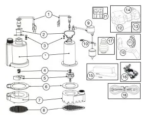
| Ref# | Description | PF92910 | PF92341 | PF92352 |
| 1 | Power Cord – Pump | 99158 | 99108 | 99108 |
| 2 | Handle | 99050 | 99053 | 99053 |
| 3 | Plug with 0-ring | 99056 | 99056 | 99056 |
| 4 | Shaft Seal | 99057 | 99057 | 99057 |
| 5 | Impeller | 99060 | 99096 | 99098 |
| 6 | Gasket | 99062 | 99088 | 99064 |
| 7 | Volute/Base | 99067 | 99078 | 99074 |
| 8 | Intake Screen | 99073 | 99073 | 99074 |
| 9 | Vertical Float Switch (includes switch, float rod, float ball & grommet | 92091 | 92010 | 92010 |
| 10 | Vertical Float Switch Bracket | 99195 | 99105 | 99105 |
| 11 | Stainless Steel Hose Clamp | 99183 | n/a | n/a |
| 12 | Battery Box | 99459 | n/a | n/a |
| 13 | Control Panel (no cover) | 99455 | n/a | n/a |
| 14 | Battery Box Cover with Control Panel | 99456 | n/a | n/a |
| 15 | 2 Amp Charger | 99454 | n/a | n/a |
| 16 | Battery Terminals (+ & – ) One Set | 99460 | n/a | n/a |
| 17 | Check Valve | 99507 | 99509 | 99509 |
| 18 | Power Cord – Control Panel | 99452 | n/a | n/a |
LIMITED WARRANTY – PRIMARY/BATTERY BACKUP PUMPS:
The manufacturer warrants the products specified In this warranty to be free from defects In material or workmanship for three (3) years from the date of purchase. During the time period and subject to the terms and conditions, the manufacturer will repair or replace to the original user or consumer any portion of this product that proves to be defective due to materials or workmanship. At all times the manufacturer shall have and possess the sole right and option to determine whether to repair or replace defective equipment. parts. or components. The manufacturer has the option to inspect any product returned under warranty to confirm that the warranty applies before repair or replacement under warranty is approved. This warranty sets forth the manufacturer’s sole obligation and purchaser’s exclusive remedy for the defective products. Return defective product to the place of purchase for warranty consideration.
WARRANTY PERIOD – PRODUCTS:
If. within the duration of product use by the original user, this product proves to be defective due to materials or workmanship, the product shall be repaired or replaced at the manufacturer’s option, subject to the terms and conditions set forth in this warranty statement. Proof of purchase is required for warranty consideration. In the absence of suitable proof of the purchase date, the effective period of this warranty is 12 months from the product’s date of manufacture.
LABOR, ETC. COSTS:
The manufacturer shall IN NO EVENT be responsible or liable for the cost of field labor or other charges incurred by any customer in removing and/or affixing any product, part, or component thereof.
PRODUCT IMPROVEMENTS:
The manufacturer reserves the right to change or improve its products or any portions thereof without being obligated to provide such a change or improvement for units sold and/or shipped prior to such change or improvement.
GENERAL TERMS AND CONDITIONS:
This warranty shall not apply to damage due to acts of God, normal wear and tear. normal maintenance services and the parts used in connection with such service, lightning, or conditions beyond the control of the manufacturer, nor shall it apply to products which. in the sole judgment of the manufacturer, have been subject to negligence, abuse, accident. misapplication, tampering, alteration; nor due to improper installation, operation, maintenance, or storage; nor to an excess of recommended maximums as set forth in the instructions. Warranty will be VOID if any of the following conditions are found:
1. Product is used for purposes other than those for which it was designed and manufactured
2. Product not installed in accordance with applicable codes, ordinances, and good trade practices
3. Product connected to a voltage other than indicated on nameplate or labels
4. Pump exposed to but not limited to the following: sand, gravel, cement, grease. plaster, mud, tar, oil, gasoline, solvents, or other abrasive or corrosive substances
5. Pump has been used for pumping liquids above 120°F
6. Pump allowed to operate dry (liquid supply cut off)
DISCLAIMER:
Any oral statements about the product made by the seller, the manufacturer, the representatives, or any other parties do not constitute warranties, shall not be relied upon by the user, and are not part of the contract for sale. Seller’s and the manufacturer’s only obligation, and buyers’ only remedy, shall be the replacement and/or repair by the manufacturer of the product as described above. NEITHER SELLER NOR THE MANUFACTURER SHALL BE LIABLE FOR ANY INJURY, LOSS OR DAMAGE, DIRECT, INCIDENTAL, OR CONSEQUENTIAL (INCLUDING, BUT NOT LIMITED TO, INCIDENTAL OR CONSEQUENTIAL DAMAGES FOR LOST PROFITS, LOST SALES, INJURY TO PERSON OR PROPERTY, OR ANY OTHER INCIDENTAL OR CONSEQUENTIAL LOSS), ARISING OUT OF THE USE OR THE INABILITY TO USE THE PRODUCT, AND THE USER AGREES THAT NO OTHER REMEDY SHALL BE AVAILABLE TO IT. Before using, the user shall determine the suitability of the product for his/her intended use, and the user assumes all risk and liability whatsoever in connection therewith.
THE WARRANTY AND REMEDY DESCRIBED IN THIS LIMITED WARRANTY IS AN EXCLUSIVE WARRANTY AND REMEDY AND IS IN LIEU OF ANY OTHER WARRANTY OR REMEDY, EXPRESSED OR IMPLIED, WHICH OTHER WARRANTIES AND REMEDIES ARE HEREBY EXPRESSLY EXCLUDED, INCLUDING BUT NOT LIMITED TO ANY IMPLIED WARRANTY OF MERCHANTABILITY OR FITNESS FOR A PARTICULAR PURPOSE, TO THE EXTENT EITHER APPLIES TO A PRODUCT SHALL BE LIMITED IN DURATION TO THE PERIODS OF THE EXPRESSED WARRANTIES GIVEN ABOVE.
Some states and countries do not allow the exclusion or limitations on how long an implied warranty lasts or the exclusion or limitation of incidental or consequential damages, so the above exclusion or limitations may not apply to you. This warranty gives you specific legal rights, and you may also have other rights which vary from state to state.
![]()
PROFLO.COM 888-6-PROFLO


