![]()
INSTALLATION &
OPERATION MANUAL
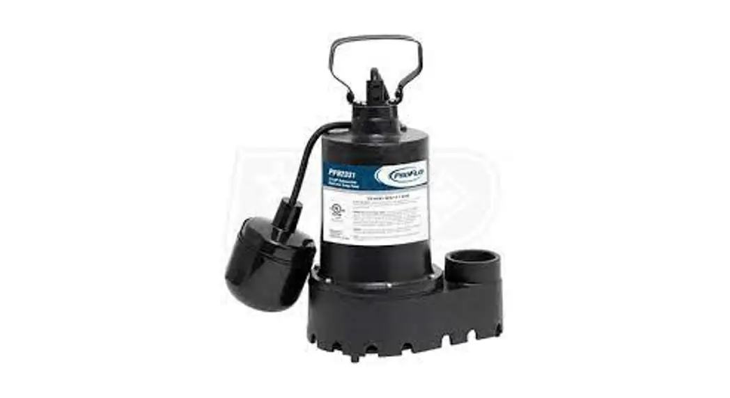
SUBMERSIBLE SUMP PUMPS
Models:
PF92331, PF92341
PF92352, PF92352-25
PF92501, PF92511
Safety Guidelines
Carefully read, understand and follow all safety instructions in this manual.![]() this is the safety alert symbol. When you see this symbol, look for one of the following signal words.
this is the safety alert symbol. When you see this symbol, look for one of the following signal words.![]() DANGER Indicates a hazardous situation that, if not avoided, will result in death or serious injury.
DANGER Indicates a hazardous situation that, if not avoided, will result in death or serious injury.![]() CAUTION Indicates a hazardous situation that, if not avoided, could result in death or serious injury.
CAUTION Indicates a hazardous situation that, if not avoided, could result in death or serious injury.![]() WARNING Indicates a hazardous situation that, if not avoided, could result in minor or moderate injury.
WARNING Indicates a hazardous situation that, if not avoided, could result in minor or moderate injury.
Safety Information
Read these warnings carefully. Know the application and limitations of this pump. Failure to follow these warnings could result in serious bodily injury and/or property damage.![]() DANGER RISK OF ELECTRICAL SHOCK. Disconnect and lockout power supply before removing old pump or installing or servicing this pump.
DANGER RISK OF ELECTRICAL SHOCK. Disconnect and lockout power supply before removing old pump or installing or servicing this pump.![]() DANGEROUS RISK OF ELECTRICAL SHOCK. This pump is supplied with a grounding conductor and grounding-type attachment plug. To reduce the risk of electric shock, be certain that it is connected only to a properly grounded, grounding-type receptacle. For added safety, it is highly recommended to connect this pump to a GFCI (Ground Fault Circuit Interrupter) outlet. Connect only to a receptacle that is adequately rated for the voltage and amperage of this bump
DANGEROUS RISK OF ELECTRICAL SHOCK. This pump is supplied with a grounding conductor and grounding-type attachment plug. To reduce the risk of electric shock, be certain that it is connected only to a properly grounded, grounding-type receptacle. For added safety, it is highly recommended to connect this pump to a GFCI (Ground Fault Circuit Interrupter) outlet. Connect only to a receptacle that is adequately rated for the voltage and amperage of this bump![]() WARNING The installation of this pump must be in accordance with the National Electric Code (NEC), Uniform Plumbing Code (UPC), International Plumbing Code (IPC) as well as all applicable local codes and ordinances.
WARNING The installation of this pump must be in accordance with the National Electric Code (NEC), Uniform Plumbing Code (UPC), International Plumbing Code (IPC) as well as all applicable local codes and ordinances.![]() CAUTION Do not install this pump in any location classified as hazardous by the National Electrical Code, ANSI/NFPA70.
CAUTION Do not install this pump in any location classified as hazardous by the National Electrical Code, ANSI/NFPA70.![]() CAUTION Do not use this pump to pump flammable or explosive fluids such as gasoline, kerosene, etc. Do not use this pump inflammable or explosive environments. Use only with liquids compatible with pump component materials.
CAUTION Do not use this pump to pump flammable or explosive fluids such as gasoline, kerosene, etc. Do not use this pump inflammable or explosive environments. Use only with liquids compatible with pump component materials.![]() WARNING RISK OF ELECTRICAL SHOCK. This pump has not been investigated for use in swimming pools or marine areas.
WARNING RISK OF ELECTRICAL SHOCK. This pump has not been investigated for use in swimming pools or marine areas.![]() WARNING RISK OF ELECTRICAL SHOCK. DO NOT use the power cord to remove or lower the pump into the basin. The cord may pull apart exposing bare wires which could cause a fire or electrical shock. Use the handle supplied with the pump for installing and removing the pump from the basin.
WARNING RISK OF ELECTRICAL SHOCK. DO NOT use the power cord to remove or lower the pump into the basin. The cord may pull apart exposing bare wires which could cause a fire or electrical shock. Use the handle supplied with the pump for installing and removing the pump from the basin.![]() WARNING Do not run the pump dry. This pump relies on water for cooling. Running the pump dry can cause the pump to overheat and the possibility of burns to anyone that handles the pump. Running the pump dry will void the warranty.
WARNING Do not run the pump dry. This pump relies on water for cooling. Running the pump dry can cause the pump to overheat and the possibility of burns to anyone that handles the pump. Running the pump dry will void the warranty.![]() WARNING Don’t expose the pump to freezing temperatures. Discharge lines exposed to freezing temperatures should be positioned with a downward slope to prevent freezing.
WARNING Don’t expose the pump to freezing temperatures. Discharge lines exposed to freezing temperatures should be positioned with a downward slope to prevent freezing.
Safety Information (continued)
![]() WARNING Do not use this pump for potable/drinking water. Use only in applications for which the pump is designed.
WARNING Do not use this pump for potable/drinking water. Use only in applications for which the pump is designed.
![]() WARNING According to the state of California (Prop 65), this product contains chemicals known to the state of California to cause cancer and birth defects or other reproductive harm.
WARNING According to the state of California (Prop 65), this product contains chemicals known to the state of California to cause cancer and birth defects or other reproductive harm.![]() WARNING DOES NOT UNDER ANY CIRCUMSTANCES REMOVE THE GROUND PIN. The 3-prong plug must be inserted into a mating 3-prong grounded receptacle. If the installation does not have such a receptacle, it must be changed to the proper type, wired, and grounded in accordance with the National Electrical Code and all applicable local codes and ordinances.
WARNING DOES NOT UNDER ANY CIRCUMSTANCES REMOVE THE GROUND PIN. The 3-prong plug must be inserted into a mating 3-prong grounded receptacle. If the installation does not have such a receptacle, it must be changed to the proper type, wired, and grounded in accordance with the National Electrical Code and all applicable local codes and ordinances.![]() WARNING All wiring must be performed by a qualified electrician.
WARNING All wiring must be performed by a qualified electrician.![]() WARNING Keep hands clear of suction & discharge openings. To prevent injury, never insert fingers into the pump while it is plugged in.
WARNING Keep hands clear of suction & discharge openings. To prevent injury, never insert fingers into the pump while it is plugged in.![]() WARNINGSump basins must be vented according to local plumbing codes. Sump basins must be vented according to local plumbing codes.
WARNINGSump basins must be vented according to local plumbing codes. Sump basins must be vented according to local plumbing codes.![]() CAUTION Do not handle this pump with wet hands or while standing on wet or damp surfaces or in water.
CAUTION Do not handle this pump with wet hands or while standing on wet or damp surfaces or in water.![]() WARNING If a flexible discharge hose is used, make sure the pump is secured in the basin to prevent movement. Failure to secure the pump could result in flooding from switch malfunction.
WARNING If a flexible discharge hose is used, make sure the pump is secured in the basin to prevent movement. Failure to secure the pump could result in flooding from switch malfunction.![]() CAUTION This pump motor is equipped with an automatic resetting thermal protector and may restart unexpectedly.
CAUTION This pump motor is equipped with an automatic resetting thermal protector and may restart unexpectedly.
Description
This Sump pump is designed to remove groundwater from residential sump pits. The motor is oil-cooled and hermetically sealed. Afloat switch is provided for automatic operation and is equipped with a 10′, 3 prong grounding type power cord.
Specifications
| Model | PF92331 | PF92341 | PF92352 | PF92352 | 25 PF92501 | PF92511 |
| HP | 1/3 | .3 | 1/3 | 1/3 | 1/2 | 1/2 |
| Volts | 120 volt AC | 120 volt AC | 120 volt AC | 120 volt AC | 120 volt AC | 120 volt AC |
| Amps | 4.1 Amps | 4.1 Amps | 5.9 | 5.9 | 7.6 | 7.6 |
| Hz | 60 Hz | 60 Hz | 60 Hz | 60 Hz | 60 Hz | 60 Hz |
| Phase | 1 | 1 | 1 | 1 | 1 | 1 |
| Discharge Size | 1-1/2″ FNPT | 1-1/2″ FNPT | 1-1/2″ FNPT | 1-1/2″ FNPT | 1-1/2″ FNPT | 1-1/2″ FNPT |
| Max. Solids Handling | 3/8″ Spherical | 3/8″ Spherical | 1/2″ Spherical | 1/2″ Spherical | 1/2″ Spherical | 1/2″ Spherical |
| Liquid Temperature Range | 32°F – 120°F 32°F | 32°F – 120°F 32°F | 32°F – 120°F 32°F | 32°F – 120°F 32°F | 32°F – 120°F 32°F | 32°F – 120°F 32°F |
| Cord Length | 10′ | 10′ | 25 | 10 | 10 | 10 |
| Switch Type | Tethered | Vertical | Vertical | Vertical | Vertical | Vertical |
| Switch on Level (Factory Set) | 10″ | 6″ | 8.5″ | 8.5″ | 11″ | 8.5″ |
| Switch off Level (Factory Set) | 5″ | 2″ | 3″ | 3″ | 5″ | 3″ |
| Pump Housing Construction | Cast Iron | Cast Iron | Cast Iron | Cast Iron | Cast Iron | Cast Iron |
| Pump Base Construction | Cast Iron | Cast Iron | Cast Iron | Cast Iron | Cast Iron | Cast Iron |
| Impeller | Stainless Steel | Stainless Steel | Thermoplastic Reinforced | Thermoplastic Reinforced | Thermoplastic Reinforced | Thermoplastic Reinforced |
| Motor Shaft | Stainless Steel | Stainless Steel | Stainless Steel | Stainless Steel | Stainless Steel | Stainless Steel |
| Shaft Seal | Carbon/ Ceramic/ Stainless | Carbon/ Ceramic/ Stainless | Carbon/ Ceramic/ Stainless | Carbon/ Ceramic/ Stainless | Carbon/ Ceramic/ Stainless | Carbon/ Ceramic/ Stainless |
| Fasteners | Steel Stainless | Steel Stainless | Steel Stainless | Steel Stainless | Steel Stainless | Steel Stainless |
| Shut off head | 26′ | 26′ | 26′ | 26′ | 26′ | 26′ |
| Max PSI | 10.8 | 10.8 | 10.8 | 10.8 | 10.8 | 10.8 |
Installation
Removing old pump (if necessary )
- Remove the old pump from the basin. If you need to cut the old discharge pipe to remove the pump, cut it as close to floor level as possible. If a check valve is attached to the pump, be prepared for water to leak from the pipe. Allow water to drain into the sump basin.
- Inspect the basin for accumulated mud, sand, silt, or small stones. Clean out the basin if necessary.
Install new pump
- Connect the discharge pipe to the pump discharge. Do not use pipe joint compound on plastic pipe or plastic pump threads as this can degrade the plastic. Use Teflon tape if necessary.
- Install a full flow, swing type check valve (sold separately) either directly into the pump discharge or on the discharge pipe. Make sure the check valve is positioned in the correct direction of flow.
- Place the pump on a solid, level surface in the basin. Use bricks or blocks to raise the pump off the bottom surface. Do not place the pump directly in mud, sand, silt, or on rocky surfaces as these materials can clog or cause damage to the pump. Do not lower the pump into the basin by the power cord or discharge pipe, use the attached handle.
- Position the pump in the basin making sure that the float switch will operate freely without coming In contact with the sides of the basin.
- Once the pump is positioned in the basin, mark and cut your existing discharge pipe to fit the height of the pump or continue installation of discharge pipe to the outside of the building.
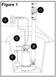 A. Grounded Outlet. A GFCI outlet is strongly recommended.
B. Discharge Pipe
C. Full-flow swing type check valve
D. Sump Basin
E. Position pump so the float switch operates freely without touching the sides of the basin.
Operation
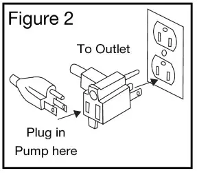
- Plug the piggy-back plug of the float switch into a 120 volt grounded outlet. The use of a GFCI is strongly recommended. Plug the pump plug into the back of the float switch plug. See Figure 2.
- Test your installation by filling the basin with water. Observe the float switch through at least one complete cycle to ensure it operates freely and does not contact the sides of the basin. If necessary, adjust the float switch or reposition the pump to ensure proper operation.

- This pump is equipped with an anti-airlock hole. A stream of water will emit from this hole when the pump is operating. This is a normal feature of this pump. The anti-airlock hole should be cleaned periodically to prevent the pump from becoming air-locked.
- Do not let the pump run dry. The pump depends on water for cooling and lubrication. Operating the pump without water may cause the motor to overheat or cause damage to internal parts. It may also shorten the life of your pump.
- Your pump motor is thermally protected. It is not recommended for pumping liquids over 120° F (49° C). The thermal overload protector will automatically shut down the pump in an overheat situation. The pump will reset itself once the pump cools down. This overload is designed as a safety device and it will fail after repeated use. Normal operation is for fluids between 32° F & 120° F (0° C – 49° C).
Maintenance
![]() DANGER Risk of electric shock. Always disconnect the power supply before attempting to install, service, or perform maintenance on the pump
DANGER Risk of electric shock. Always disconnect the power supply before attempting to install, service, or perform maintenance on the pump![]() WARNING All repairs must be made by an authorized service center.
WARNING All repairs must be made by an authorized service center.![]() CAUTION This submersible pump contains oil that may become pressurized and hot under normal operating conditions – allow the pump to cool for 2-3 hours before serving.
CAUTION This submersible pump contains oil that may become pressurized and hot under normal operating conditions – allow the pump to cool for 2-3 hours before serving.
- The pump motor is hermetically sealed in the housing and does not require any service. Disassembly of the motor housing or modification of the power cord voids the warranty.
- Periodically check the sump basin for the accumulation of mud, silt, sand, and foreign objects. Clean the basin as needed to prevent damage or clogging of the pump.
- Periodically check the removable intake screen for obstructions. Clean if necessary.
- Periodically inspect and clean the anti-airlock hole.
- Inspect the float switch for any accumulated debris that may inhibit it from operating properly. Clean if necessary.
- Inspect the impeller for signs of wear and obstructions.
- Inspect the power cord for signs of damage or wear. Do not operate the pump if the cord is damaged or worn.
- In applications where the pump may not activate for extended periods of time, it is recommended to cycle the pump at least once per month to ensure the pumping system is working properly when needed.
Troubleshooting
| Problem Possible Causes | How to Correct | |
| If the pump does not start or run | Pump ks not plugged in, switch or breaker is turned off | Plug pump in or turn on switch breaker |
| Check for blown fuses or tripped circuit breakers or tripped GFCI outlets | Replace fuse reset breaker, reset GFCI | |
| outlet | ||
| The float switch is defective | Check and replace if necessary | |
| Motor thermal protector tripped | Allow the pump to cool. The pump will reset automatically | |
| The float switch is stuck or obstructed | Remove obstruction or position pump so the float switch will operate freely | |
| The pump starts and stops too often | Backflow of water from discharge hose/pipe pi | Install or replace check valve |
| The float switch is defective | Replace float switch | |
| If the pump runs but moves little or no water | Clogged discharge hose/pipe | Remove clog |
| Frozen discharge hose/pipe | Allow hose/pipe to thaw | |
| The pump is air locked | Check airlock hole for clogs and clean if necessary | |
| Low line voltage | Check wire size and increase If necessary | |
| A check valve is stuck in the closed position | Inspect, repair or replace it necessary | |
| A check valve is installed backward | Make sure the check valve Is installed In the correct direction of flow | |
| Clogged Intake screen | Clean or replace the screen | |
| Worn, damaged, or clogged pump parts | Inspect for wear, damage or clog and clean or replace the part if necessary | |
| Discharge head exceeds pump capacity | See performance chart for pump limitations | |
| Pump does not shut off | The float switch is obstructed or stuck | Remove obstruction |
| Defective Float Switch | Replace float switch | |
Performances
Height and/or piping restrictions will reduce the pump output performance. It is recommended to use the same size or larger pipe as the pump discharge for optimum performance.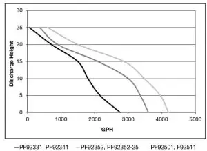
| Model | Discharge Height | 0” | 5” | 10” | 15” | 20” | 25” |
| PF92331 PF92331 | Gallons Per Minute | 46 | 36 | 30 | 25 | 12 | 1 |
| PF92352 PF92352-25
| Gallons Per Minute | 60 | 56 | 50 | 35 | 15 | 6 |
| PF92352 PF92352-11
| Gallons Per Minute | 70 | 66 | 58 | 48 | 25 | 10 |
Replacement Parts – To order replacement parts call 888-6-PROFLO
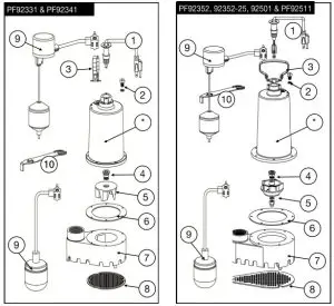
Ref# | Description | PF92331 PF92341 | PF92352 | PF92352- 25 | PF92501 |
| 1 | 10 Ft. Power Cord | 99108 | 99108 | – | 99108 |
| 1 | 25 Ft. Power Cord | – | 99109 | ||
| 2 | Oil Fill Plug with 0-ring | 99056 | 99056 | 99056 | 99056 |
| 3 | Handle | 99053 | 99053 | 99053 | 99053 |
| 4 | Shaft Seal | 99057 | 99057 | 99057 | 99057 |
| 5 | Impeller | 99096 | 99098 | 99098 | 99098 |
| 6 | Gasket | 99088 | 99064 | 99064 | 99064 |
| 7 | BaseNolute | 99078 | 99071 | 99071 | 99071 |
| 8 | Intake Screen | 99073 | 99074 | 99074 | 99074 |
| 9 | Float Switch (92010 Vertical Float Switch includes a switch, float rod, float ball, and grommet) | 92000 | 92010 | 92010 | 92000 |
| 92010 | 92010 | ||||
| 10 | Vertical float Switch Bracket | n/a | 99105 | 99105 | n/a |
| 99105 | 99105 |
‘If the motor fails, replace the entire pump
LIMITED WARRANTY – SUMP PUMPS:
The manufacturer warrants the products specified in this warranty to be free from defects in material or workmanship for five (5) years from the date of purchase. During the time period and subject to the terms and conditions, the manufacturer will repair or replace to the original user or consumer any portion of this product that proves to be defective due to materials or workmanship. At all times the manufacturer shall have and possess the sole right and option to determine whether to repair or replace defective equipment, parts, or components. The manufacturer has the option to inspect any product returned under warranty to confirm that the warranty applies before repair or replacement under warranty is approved. This warranty sets forth the manufacturer’s sole obligation and purchaser’s exclusive remedy for the defective products. Return defective product to the place of purchase for warranty consideration.
WARRANTY PERIOD – PRODUCTS:
If within the duration of product use by the original user, this product proves to be defective due to materials or workmanship, the product shall be repaired or replaced at the manufacturer’s option, subject to the terms and conditions set forth in this warranty statement. Proof of purchase is required for warranty consideration. In the absence of suitable proof of the purchase date, the effective period of this warranty is 12 months from the product’s date of manufacture.
LABOR, ETC. COSTS:
The manufacturer shall IN NO EVENT be responsible or liable for the cost of field labor or other charges incurred by any customer in removing and/or affixing any product, part, or component thereof.
PRODUCT IMPROVEMENTS:
The manufacturer reserves the right to change or improve its products or any portions thereof without being obligated to provide such a change or improvement for units sold and/or shipped prior to such change or improvement.
GENERAL TERMS AND CONDITIONS: This warranty shall not apply to damage due to acts of God, normal wear and tear, normal maintenance services, and the parts used in connection with such service, lightning, or conditions beyond the control of the manufacturer, nor shall it apply to products which, in the sole judgment of the manufacturer, have been subject to negligence, abuse, accident, misapplication, tampering, alteration; nor due to improper installation, operation, maintenance or storage; nor to an excess of recommended maximums as set forth in the instructions. Warranty will be VOID if any of the following conditions are found:
- Product is used for purposes other than those for which it was designed and manufactured
- Product not installed in accordance with applicable codes, ordinances, and good trade practices
- Product connected to a voltage other than indicated on nameplate or labels
- Pump exposed to but not limited to the following: sand, gravel, cement, grease, plaster, mud, tar, oil, gasoline, solvents, or other abrasive or corrosive substances
- The pump has been used for pumping liquids above 120°F
- Pump allowed to operate dry (liquid supply cut off) DISCLAIMER:
DISCLAIMER: Any oral statements about the product made by the seller, the manufacturer, the representatives, or any other parties do not constitute warranties, shall not be relied upon by the user, and are not part of the contract for sale. Seller’s and the manufacturer’s only obligation, and buyer’s only remedy, shall be the replacement and/or repair by the manufacturer of the product as described above. NEITHER SELLER NOR THE MANUFACTURER SHALL BE LIABLE FOR ANY INJURY, LOSS OR DAMAGE, DIRECT, INCIDENTAL, OR CONSEQUENTIAL (INCLUDING, BUT NOT LIMITED TO, INCIDENTAL OR CONSEQUENTIAL DAMAGES FOR LOST PROFITS, LOST SALES, INJURY TO PERSON OR PROPERTY, OR ANY OTHER INCIDENTAL OR CONSEQUENTIAL LOSS), ARISING OUT OF THE USE OR THE INABILITY TO USE THE PRODUCT, AND THE USER AGREES THAT NO OTHER REMEDY SHALL BE AVAILABLE TO IT. Before using, the user shall determine the suitability of the product for his/her intended use, and the user assumes all risk and liability whatsoever in connection therewith. THE WARRANTY AND REMEDY DESCRIBED IN THIS LIMITED WARRANTY IS AN EXCLUSIVE WARRANTY AND REMEDY AND IS IN LIEU OF ANY OTHER WARRANTY OR REMEDY, EXPRESSED OR IMPLIED, WHICH OTHER WARRANTIES AND REMEDIES ARE HEREBY EXPRESSLY EXCLUDED, INCLUDING BUT NOT LIMITED TO ANY IMPLIED WARRANTY OF MERCHANTABILITY OR FITNESS FOR A PARTICULAR PURPOSE, TO THE EXTENT EITHER APPLIES TO A PRODUCT SHALL BE LIMITED IN DURATION TO THE PERIODS OF THE EXPRESSED WARRANTIES GIVEN ABOVE. Some states and countries do not allow the exclusion or limitations on how long an implied warranty lasts or the exclusion or limitation of incidental or consequential damages, so the above exclusion or limitations may not apply to you. This warranty gives you specific legal rights, and you may also have other rights which vary from state to state.![]() PROFLO.COM 888-6-PROFILE
PROFLO.COM 888-6-PROFILE


