![]()
INSTRUCTION MANUAL
www.jbctools.com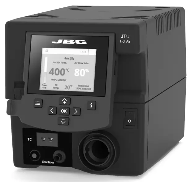
JTU
Hot Air Control Unit
This manual corresponds to the following references:
Packing List
The following items are included:
JTSE-1UA (100V / 120V)
JTSE-2UA (230V) JTU Control Unit …………………………………1 unit
 Power cable ………………………………………….1 unit
Ref. 0023715 (100V / 120V)
0023714 (230V)
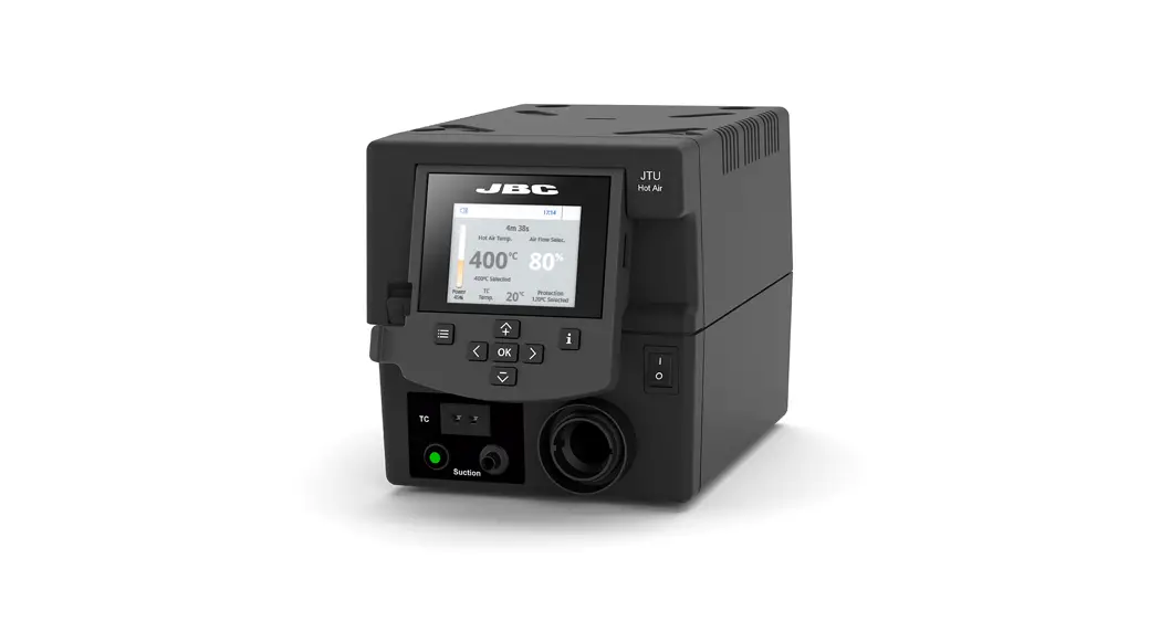
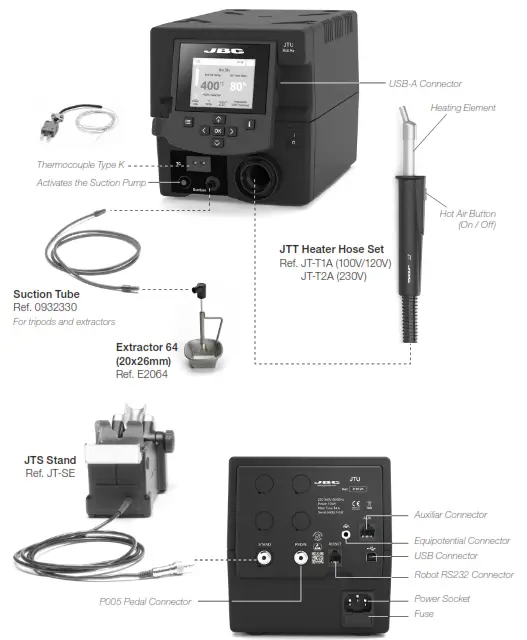
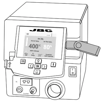
Features and Connections
JT / TE Work Screen
JT/TE offers an intuitive user interface that provides quick access to station parameters.
Default PIN: 0105
Troubleshooting
Station troubleshooting is available on the product page at www.jbctools.com
Advanced Functionalities
 To work with profiles it is essential to use RWB / RWS / RWT rework arms. In this mode, you can set up or edit as many as 25 airflows and temperature profiles.
Rework Arms supports the Hot Air Heater maintaining the distance and position to the component. 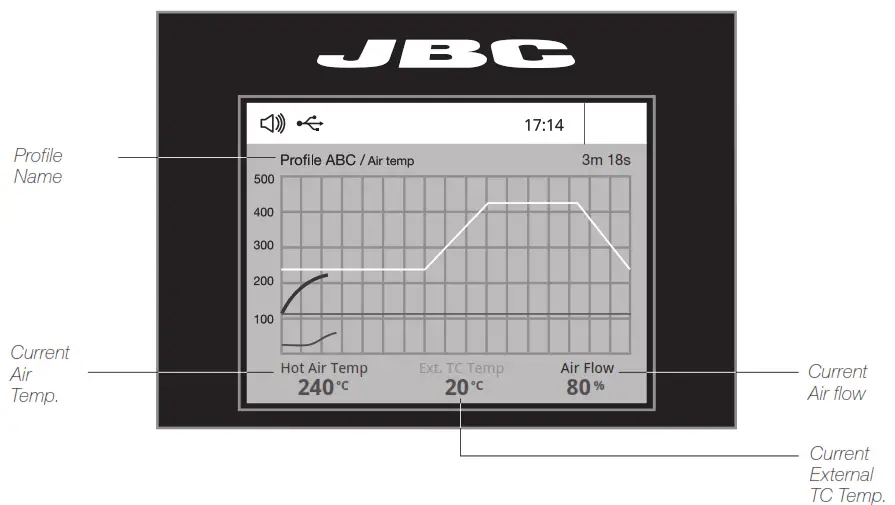 Edit Mode
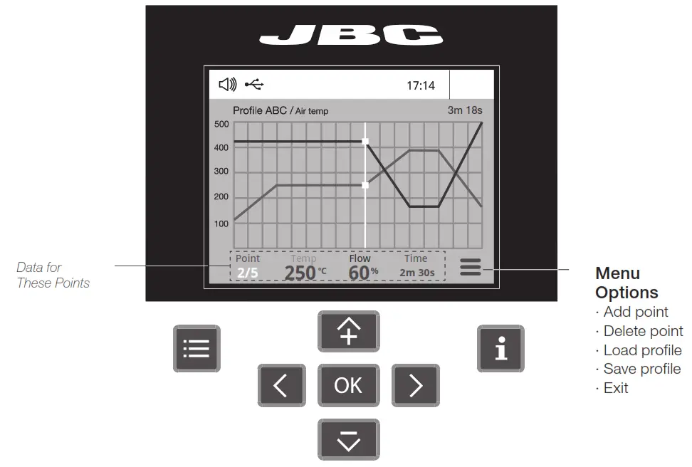
 By pressing Graphics in the main MENU, temperature and power fi figures in real-time are displayed. This helps you decide which nozzle to use to obtain the best quality solder joints.
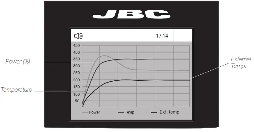
 | The fi rst system to optimize traceability in soldering – Get greater quality and control in your production – Manage your whole soldering process remotely in real-time |
| Export Graphics Insert a USB flash drive into the USB-A connector to save your soldering process in csv format. | |
| Station Update Download the JBC Update File from www.jbctools.com/software.html Insert the USB flash drive with the file downloaded the station. |
System Notifications
The following icons will be displayed on the screen’s status bar.
 | USB fl ash drive is connected. |
| The station is controlled by a PC. | |
| The station is controlled by a robot. |
 | Station software update. Press INFO to start the process. |
| Warning. Press INFO for failure description. | |
| Error. Press INFO for failure description, the type of error and how to proceed. |
Adjustable Stand
Adjust the tool holder angle to suit your work position.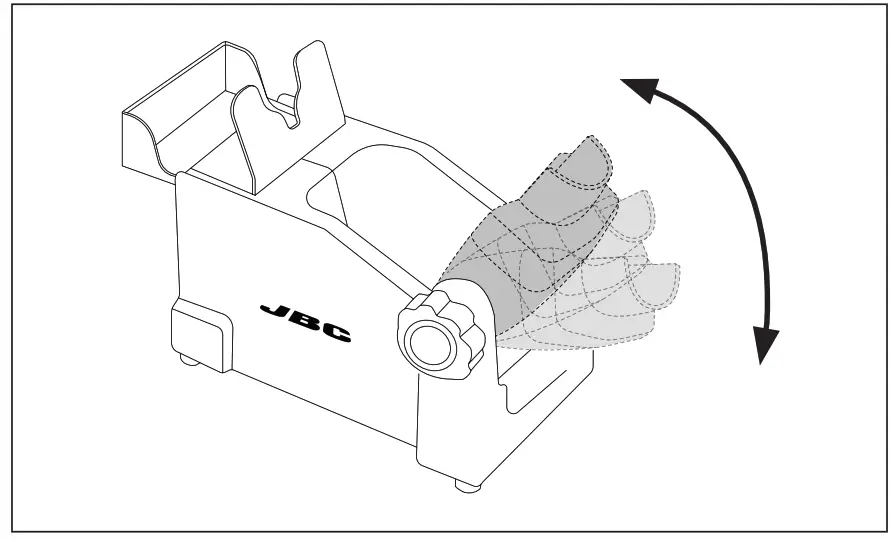
Operation Modes
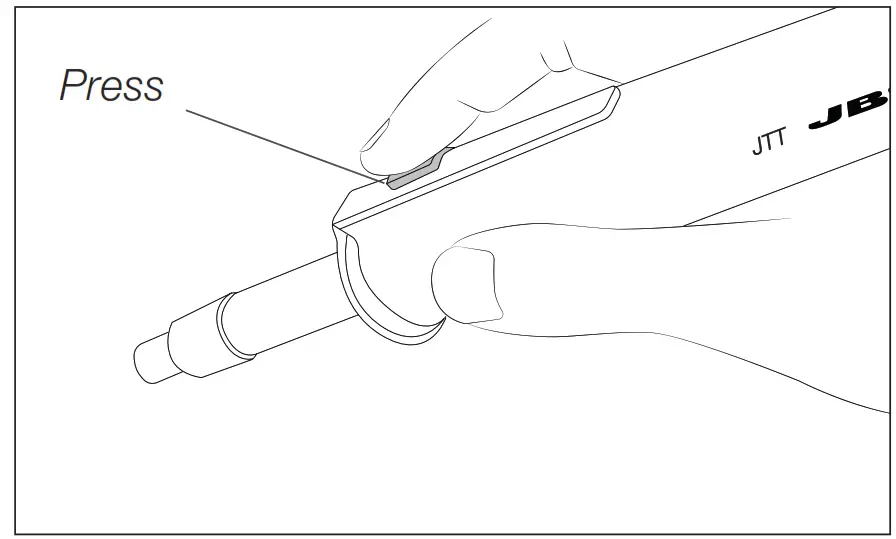
- From the Tool Settings Menu, select the mode to activate the tool depending on the task.
Tool button Press the start/stop button to blow hot air.
Pedal (not included) Press the Pedal (Ref. P-305) to blow hot air and release to stop.
 - The tool stops blowing when pressing the start/stop button.
If the stand is connected to the station and for safety it will also stop when returned to the stand.
 Press the start/stop button to blow hot air.
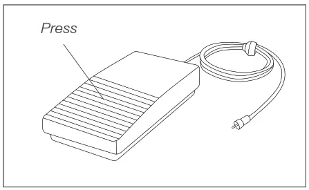 Press the Pedal (Ref. P-305) to blow hot air and release to stop.
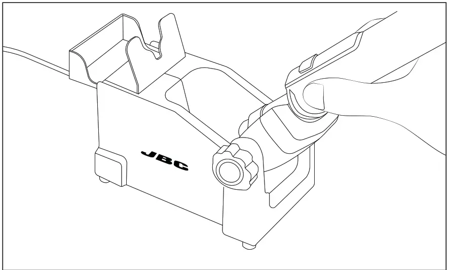
Operation
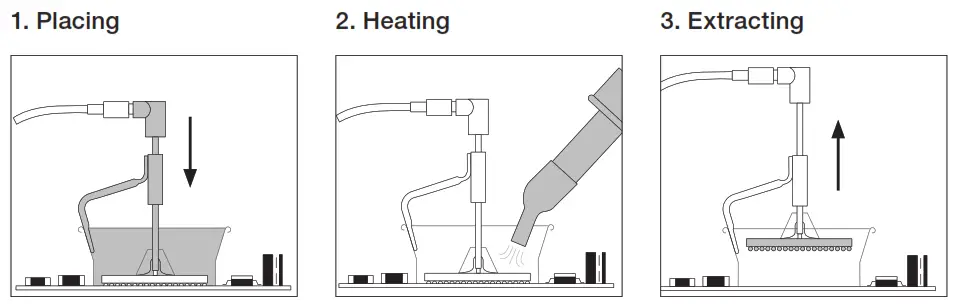 | ||
| Position the extractor with the appropriate suction cup and press the suction button. | Heat the component. | The component lifts off automatically when the solder melts. |
Protectors & Extractors
For small components (fig. 1 and 2).
We recommend using the protector + tripod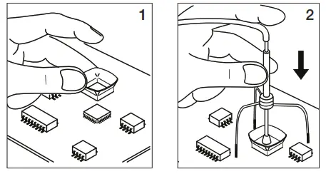
For large components (fig. 3 and 4).
We recommend using the manual extractors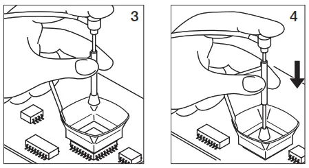
Accessories (not included)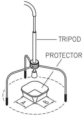
Protectors
| No.* | Ref. | AxB (mm) | AxB (in) | No.* | Ref. | AxB (mm) | AxB (in) |
| P3353 | 4,3 x 3 | 0.16 x 0.12 | P1249 | 12 x 23 | 0.47 x 0.9 | ||
| P3786 | 5,2 x 5,2 | 0.20 x 0.20 | 44 | P4000 | 12,5 x 12,5 | 0.49 x 0.49 | |
| P3352 | 5,2 x 7,5 | 0.20 x 0.29 | P3354 | 13,2 x 13,2 | 0.52 x 0.52 | ||
| P3355 | 5,2 x 9,5 | 0.20 x 0.37 | P4025 | 13,5 x 21,5 | 0.53 x 0.85 | ||
| P3356 | 6,2 x 4,2 | 0.24 x 0.16 | 48 | P2230 | 15 x 15 | 0.59 x 0.59 | |
| P3785 | 7,2 x 7,2 | 0.28 x 0.28 | 60 | P4010 | 17 x 17 | 0.67 x 0.67 | |
| P3784 | 8,2 x 8,2 | 0.32 x 0.32 | P4005 | 18 x 29 | 0.71 x 1.14 | ||
| P4035 | 9 x 13 | 0.35 x 0.51 | P4030 | 18,5 x 18,5 | 0.73 x 0.73 | ||
| P4040 | 9,5 x 19 | 0.7 x 0.74 | P1068 | 18,5 x 24 | 0.73 x 0.94 | ||
| P4080 | 9,5 x 21 | 9.5 x 0.83 | P2685 | 28,5 x 28,5 | 1.12 x 1.12 | ||
| 32 | P2220 | 10 x 10 | 0.39 x 0.39 | P4085 | 31,5 x 31,5 | 1.24 x 1.24 | |
| P4045 | 10,5 x 21 | 0.14 x 0.82 | P2672 | 33 x 46 | 1.30 x 1.18 | ||
| P4090 | 11 x 16 | 0.43 x 0.63 | P4002 | 50 x 50 | 1.97 x 1.97 | ||
| 24 | P2235 | 12 x 17 | 0.47 x 0.67 | P3357 | 52,5 x 14 | 2.06 x 0.55 |
Extractors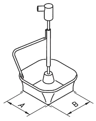
| No.* | Ref. | AxB (mm) | AxB (in) No.* | Ref. | AxB (mm) | AxB (in) | |
| 52 | E2052 | 20 X 20 | 0.79 x 0.79 | E4015 | 31,5 X 31,5 | 1.24 x 1.24 | |
| 64 | E2064 | 20 X 26 | 0.79 x 1.02 | E2084 | 33 X 33 | 1.30 x 1.30 | |
| 80 | E2184 | 24 X 24 | 0.94 x 0.94 | E2100 | 38 X 38 | 1.50 x 1.50 | |
| E2068 | 27 X 27 | 1.06 x 1.06 | E2124 | 45 X 45 | 1.77 x 1.77 | ||
| E4020 | 28,5 X 28,5 | 1.12 x 1.12 | |||||
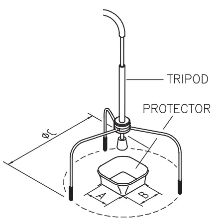
Tripods
| Ref. | øC (mm) | øC (in) |
| T2050 | 39 | 1.53 |
| T2250 | 85 | 3.35 |
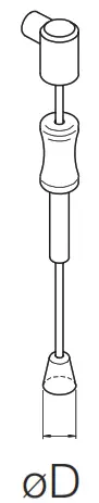
Manual extractor
| Ref. | øD (mm) | øD (in) |
| E2190 | 7 | 0.27 |
* Position in Extractor Stand
Using the Thermocouple Type K
Connect a TC type K (PH218) to the station and use it as a protection or regulation sensor.
You can choose from two work modes:
You can define its use mode by means of the “Ext TC mode” option in the “Tool” menu.
Regulation: the station regulates the air temperature automatically to maintain the External Thermocouple (TC) temperature.
Protection: the station cuts the air supply off when the External Thermocouple (TC) temperature is reached.
Fix the TC with Kapton Tape (Ref. PH217) as near as possible to the component being worked on.
If Kapton tape is not ESD you must use an ionizer.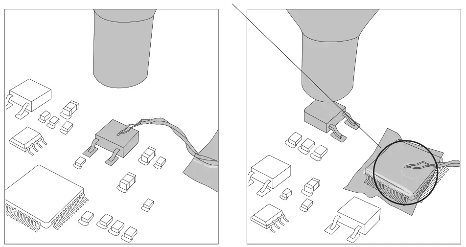
IPC* does not recommend exceeding ramp-up rates over 3-4ºC / sec. (5-7ºF / sec) so as to reduce the risk of thermal stress on the PCB.
* IPC was founded in the U.S. in 1957 as the Institute for Printed Circuits.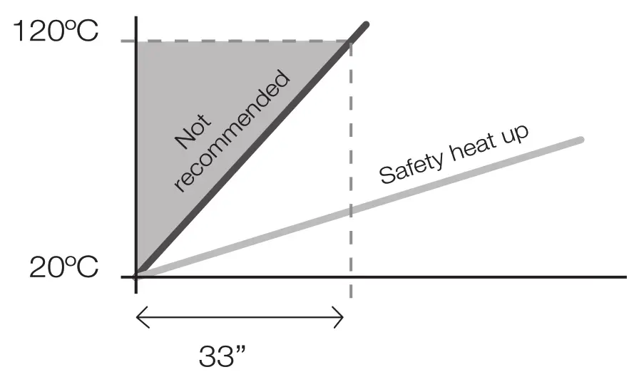
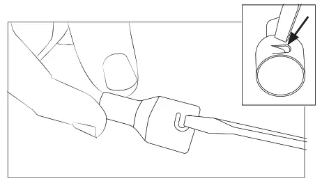
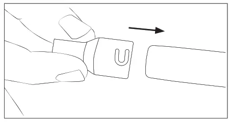
Quick Nozzle Changer
Changing nozzles quickly and safely.![]() Turn the tool off and handle with care.
Turn the tool off and handle with care.
The heating element and the nozzle are still hot.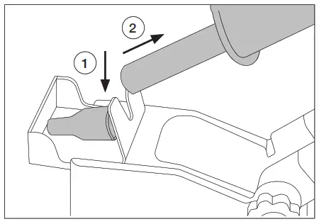
Compatible Nozzles
JTT works with JT nozzles. Find the model that best suits your soldering needs in www.jbctools.com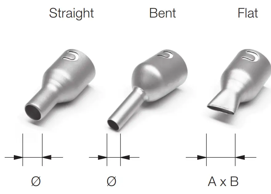
| * | Ref. | Shape | Size (mm) | Size (in) |
| * | JN2020 | Straight | Ø 8 | Ø 0.31 |
| * | JN8417 | Straight | Ø 10 | Ø 0.4 |
| * | JN2015 | Bent | Ø 4 | Ø 0.16 |
| JN2012 | Bent | Ø 6 | Ø 0.24 | |
| JN6633 | Bent | Ø 8 | Ø 0.31 | |
| JN7637 | Flat | 10 x 2 | 0.39 x 0.08 | |
| JN7638 | Flat | 20 x 2 | 0.79 x 0.08 | |
| JN7639 | Flat | 30 x 2 | 1.18 x 0.08 |
* Supplied with JT
In case of a loosely fitting nozzle:
- Push the nozzle tab inwards with a screw-driver or flat-nosed pliers.

- Assemble the nozzle onto JTT again.

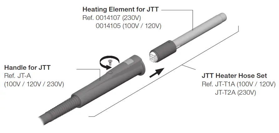
Replacing the Heating Element
Only perform this operation when the element is cold and the unit is disconnected from the mains.
- Loosen the screw.
- Pull the heating element out of the handle.
- Connect the new heating element, ensuring it is pushed all the way in.
- Tighten the screw.
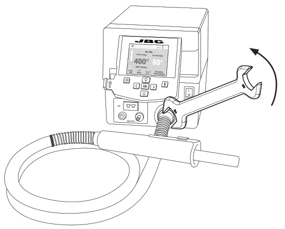
Changing the JTT Heater Hose Set
- Unplug the power cable.
- Use a spanner to unscrew the nut.
- Make sure that the new heater tube fits into the grooves in the socket.
- Tighten the screw.

Maintenance
Before carrying out maintenance, always allow the equipment to cool.
- Clean the station screen with a glass cleaner or a damp cloth.
- Use a damp cloth to clean the casing and the tool. Alcohol can only be used to clean the metal parts.
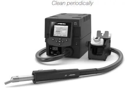
- Periodically check that the metal parts of the tool and stand are clean so that the station can detect the tool status.
- Periodically check all cables and tubes.
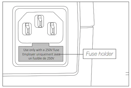
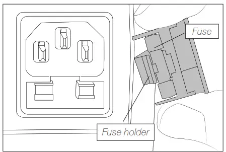
- Replace a blown fuse as follows:

- Pull off the fuse holder and remove the fuse. If necessary use a tool to lever it off.

- Insert the new fuse into the fuse holder and return it to the station.
– Replace any defective or damaged pieces. Use original JBC spare parts only.
– Repairs should only be performed by a JBC-authorized technical service.
Safety
![]() It is imperative to follow safety guidelines to prevent electric shock, injury, fire or explosion.
It is imperative to follow safety guidelines to prevent electric shock, injury, fire or explosion.
- Do not use the units for any purpose other than soldering or rework. Incorrect use may cause fire.
- The power cord must be plugged into approved bases. Be sure that it is properly grounded before use. When unplugging it, hold the plug, not the wire.
- Do not work on electrically live parts.
- The tool should be placed in the stand when not in use in order to activate the sleep mode.
The soldering tip or nozzle, the metal part of the tool and the stand may still be hot even when the station is turned off. Handle with care, including when adjusting the stand position. - Do not leave the appliance unattended when it is on.
- Do not cover the ventilation grills. Heat can cause inflammable products to ignite.
- Avoid flux coming into contact with skin or eyes to prevent irritation.
- Be careful with the fumes produced when soldering.
- Keep your workplace clean and tidy. Wear appropriate protection glasses and gloves when working to avoid personal harm.
- Utmost care must be taken with liquid tin waste which can cause burns.
- This appliance can be used by children over the age of eight and also persons with reduced physical, sensory or mental capabilities or lack of experience provided that they have been given adequate supervision or instruction concerning use of the appliance and understand the hazards involved. Children must not play with the appliance.
- Maintenance must not be carried out by children unless supervised.
Specifications
JTU
Hot Air Control Unit
Ref.: JTSE-1UA 100V – 120V 50/60Hz. Input fuse: 8A. Rated current: 7A
Ref.: JTSE-2UA 230V 50/60Hz. Input fuse: 4A. Rated current: 3A
| – Temperature selection: | Room temp. 150 – 450 °C / 300 – 840 °F |
| – Nominal power: | 700W |
| – Cool mode: | T off. Used to blow air to room temperatur |
| – Ambient operating temp.: | 10 – 50 ºC / 50 – 122 ºF |
| – Air flow regulation: | 5 – 50 SLPM |
| Vacuum: | 30% / 228 mmHg / 9 inHg |
| – Connectors: | USB station-PC Robot RS232 P-005 Pedal |
| – Control Unit Dimension/Weight: | 1.90 kg / 4.2 lb |
| – Total Net Weight: | 230 x 148 x 160 mm / 5.83 x 7.24 x 5.51 in |
| – Total Package Dimension/Weight: | 258 x 328 x 208 mm / 2.56 kg 10.15 x 12.9 x 8.2 in / 5.64 lb |
Complies with CE standards.
ESD safe.
Warranty
JBC’s 2 year warranty covers this equipment against all manufacturing defects, including the replacement of defective parts and labour.
Warranty does not cover product wear or misuse. In order for the warranty to be valid, equipment must be returned, postage paid, to the dealer where it was purchased.
Get 1 extra year JBC warranty by registering here: https://www.jbctools.com/productregistration/within 30 days of purchase.![]() This product should not be thrown in the garbage.
This product should not be thrown in the garbage.
In accordance with the European directive 2012/19/EU, electronic equipment at the end of its life must be collected and returned to an authorized recycling facility.
a manuales – color gris ![]()
www.jbctools.com
0027698-1021


hot Air Station Instruction Manual")
 Precision Hot Air Station Instruction Manual")
high Precision Hot Air Station Instruction Manual")


hot Air Station Extractor Desk Instruction Manual")


