![]() A2 High-Quality Multifunction Inverter
A2 High-Quality Multifunction Inverter
Instruction Manual
Preface
Thank you very much for choosing the high-quality, multifunction, low-level noise, and energy-cost product by Isacson Power Control Tech. Co., Ltd –A2 series inverters.
This manual contains the user setup, parameter setting, fault diagnosis, daily maintenance, and safety precautions.
Please read this manual carefully before installing and operating the products. This manual is contained in the accessories of the productions. Please keep it safe for further referencing.
If there is any problem that isn’t listed in this manual, please contact the local dealer or Isacon’s custom service center.
Phone:057687161633(10 Line)-Department of Technology
Fax.:057687161633-8005
Chapter 1 Safety Precautions
1.1 Safety precautions
- The environment cannot contain any explosive gas.
- It must be wired by professional wiring staff. Otherwise, it may cause electronic shock.
- Cut off the power supply before wiring. Otherwise, it may cause electronic shock.
- Do not touch any control port, internal boards, and electronic components while the electricity is turned on.
- Otherwise, it may cause electronic shock.
- Please make sure that the product’s ground wiring port is correctly connected according to national electrical safety standards or other related standards.
- Do not touch any internal board or component until 10 minutes after power shutdown. Please do an electricity check before internal board maintenance. Otherwise, it may cause electronic shock.
- It is forbidden to connect AC power to the product’s output port (U, V, W) or other control ports except for Lk, Lb,Lz. Otherwise, it may cause damage to the inverter.
- Since internal IC can be destroyed by electrostatic, please do not touch any PCB, IC, or IGBT components without any protection. Otherwise, it may cause an unknown fault.
- Make sure that any unexpected conductor such as screws, gaskets, etc., is not left inside the inverter during maintenance.
- Otherwise, it may cause damage to the inverter or even fire.
- If an overcurrent happens during starting up, please check the wiring and start up again.
- Do not stop the machine by cutting off power. Power can be cut off after the motor stops.
- Do not leave the inverter in the sunshine. Otherwise, it may cause damage to the inverter.
1.2 Package inspection
A2 series inverter production undergoes a strict qualification test.
Please check the damage caused by the delivery and the type specification during package inspection.
- Accessories: 1 Inverter, 1 user manual.
- If anything is missing, please contact the local dealer or Isacon’s custom service center.
Chapter 2 User Setup
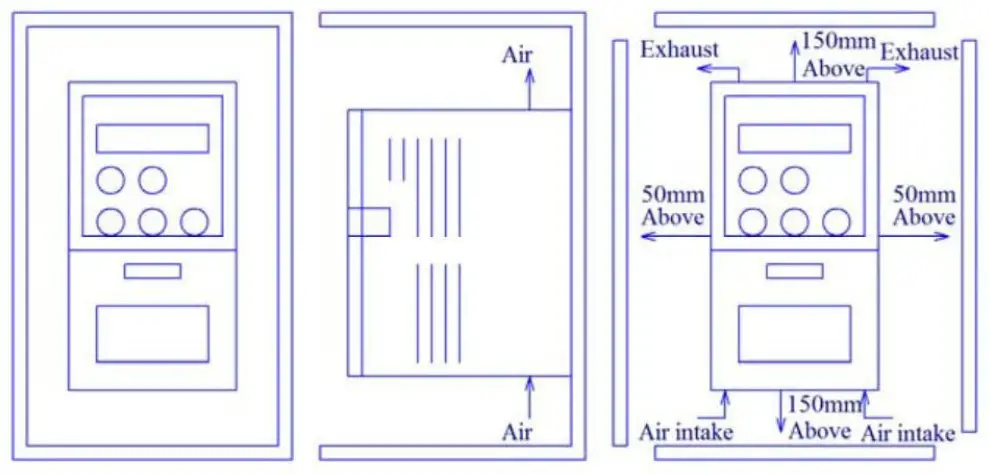
2.1 Environment requirement
- No corrosive gas, vapor, or oily dust. Without direct sunshine.
- No floating dust or mental particles.
- Air moisture 20%~90%.
- Vibration < 5.8m/s2(0.6g).
- No electromagnetic interference.
- Temperature:-10℃~50℃, make sure proper ventilation if the temperature is greater than 40℃.
- Without any inflammable or explosive gas, liquid and solid.
Please use an electric cabinet or remote operation in a non-standard environment. Make sure proper ventilation.
2.2 Install space
2.3 Basic wiring
There is two wiring parts: the main loop and the control loop. Please do wiring correctly according to the following two figures.
Wiring figure (single phase)
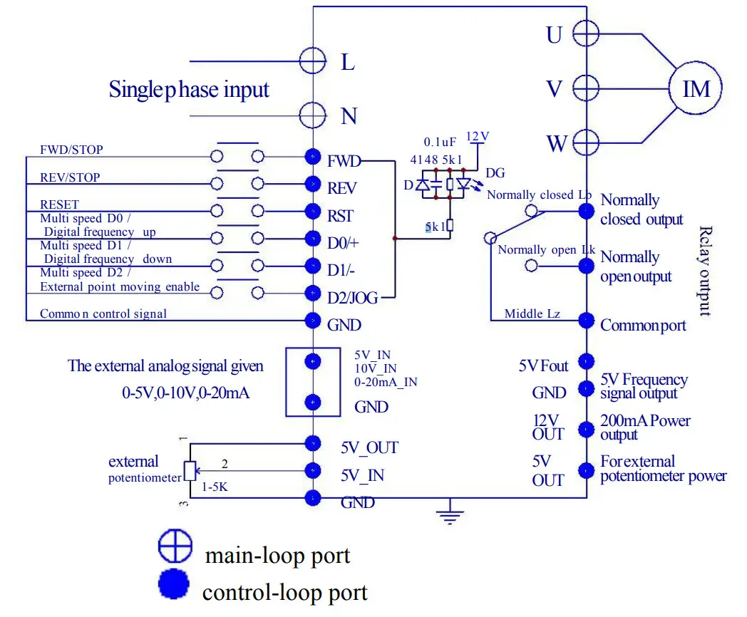
| Port name | Description |
| L N | Single phase power input. |
| U V W | Three-phase AC output ports can only connect to pure resistance or inductance load such as motors or electric heaters. |
Wiring figure (three phases)
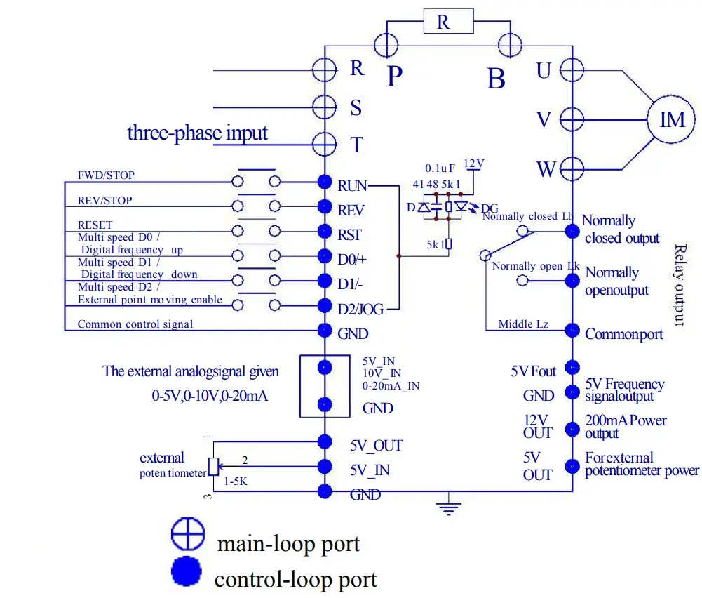
| Port name | Description | ||
| R | S | T | Single phase 220V power connects R and T. |
| Three-phase 220V power connect R, S, and T. | |||
| R | S | T | Voltage specifications: 8m, single phase 220 input connection R and T |
| U | V | W | Three-phase AC output ports can only connect to pure resistance or inductance loads such as motors or electric heaters. |
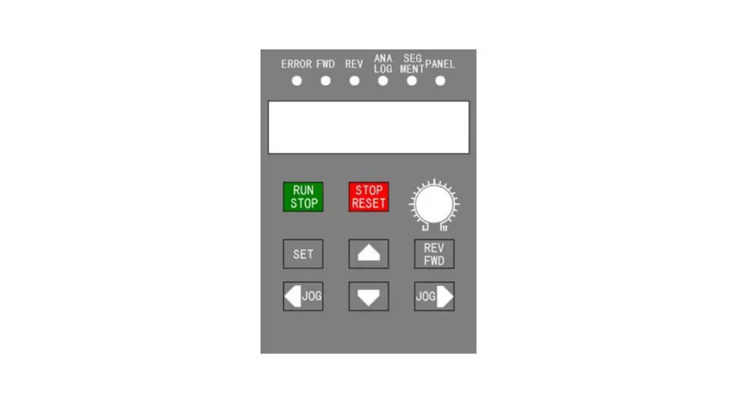
Chapter 3 Control Panel
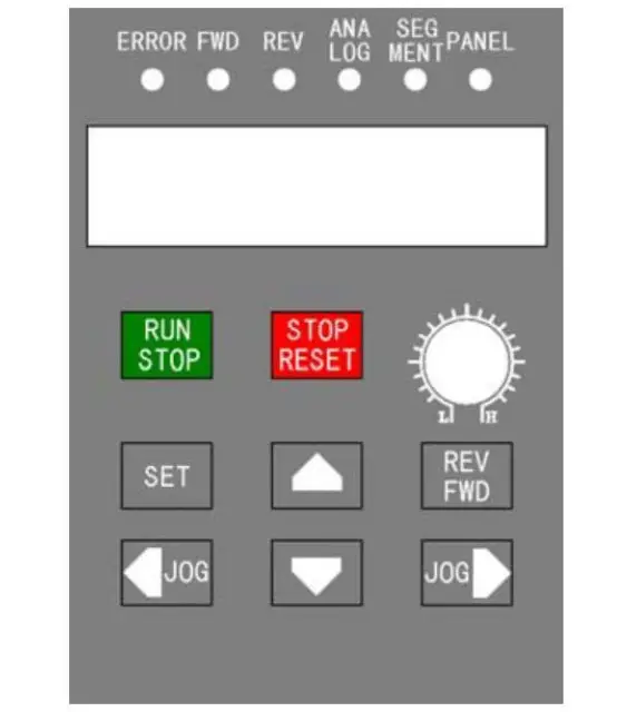
| Button | Description |
| RUN STOP | Switch between run and stop states with a single press. |
| STOP RESET | It has different meanings to push this button during different modes: l. if the inverter is running, it would stop; 2. If a fault happens, the inverter would be reset; 3. If it is operated on menus, it returns to the parent menu. |
| REV | Change the inverter’s direction. It also works during the runtime. |
| SET | Enter menu mode. If it is on an item, the data would be saved and the lower-level menu would be displayed. |
| ♦ V | Change items in the menu or modify the parameter data. |
| • ► | Modify the menu content and point move in the panel. |
| Potentiometer | Change runtime frequency. |
| Content | Description |
| ERROR | Fault indicator. |
| FWD | Clockwise rotation indicator. |
| REV | Anticlockwise rotation indicator. |
| ANALOG | Analog input frequency indicator. |
| SEGMENT | Segment input frequency indicator. |
| PANEL | Panel input frequency indicator. |
| Digital tube | Inverter runtime frequency. If the inverter stops, it flashes. The display data is given by “Pn01” data. |
Chapter 4 Parameter Set Method
4.1 Parameter set and modification
Set the parameter when the inverter is stopped and the parameter is not locked (Pn32=1). First, enter the parameter set menu by pushing the button “SET”. Second, push the button ▲/▼ to choose a certain item. Third, push the button “SET” again to enter the item. Fourth, push button ◄/► to choose a certain bit and push ▲/▼ to modify the value. Finally, push button “SET” to save the new parameter or push the button “STOP” to the parent menu without any saving.
Push the button “SET” to save the new parameter or push the button “STOP” to the parent menu without any saving.
4.2 Button notice
When modify parameters, long push ▲/▼ to rolling number of current bit between 0-9.
Chapter 5 Table of Configure Parameters
| Item | Description Modify by button ▲ or ▼ | Range Modify by button ▲ or ▼ | Default Value | |
| Default (3) | Default (6) | |||
| Pn 01 | Default display content | 1-30000 | 1 | 1 |
| Pn 02 | Initial start-up frequency by a panel or another method | 0.01-400.00.00 | 400Hz | 50 |
| Pn 03 | Source of runtime frequency | 1 —7 | 2 | 1 |
| Pn 04 | Source of runtime command | 1 —2 | 1 | 1 |
| Pn 05 | clockwise / anticlockwise disable | 1 —3 | 3 | 3 |
| Pn 06 | Method to stop inverter | 1 —2 | 2 | 2 |
| Pn 07 | Start again by external signal | 1 —2 | 1 | 1 |
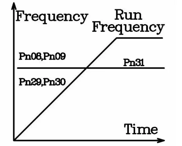
| Pn 08 | Acceleration time | 000.01S-650.00S | 50S | 10S |
| Pn 09 | Deceleration time | 000.01S-650.00S | 505 | 10S |
| Pn 10 | Maximum runtime frequency | 000.10Hz-400.00Hz | 400Hz | 50Hz |
| Pit I I | Minimum runtime frequency | 000.10Hz-400.00II/ | 1.5Hz | 1.5Hz |
| Pn 12 | Motor rating frequency | 010.00Hz-400.00Hz | 400Hz | 50Hz |
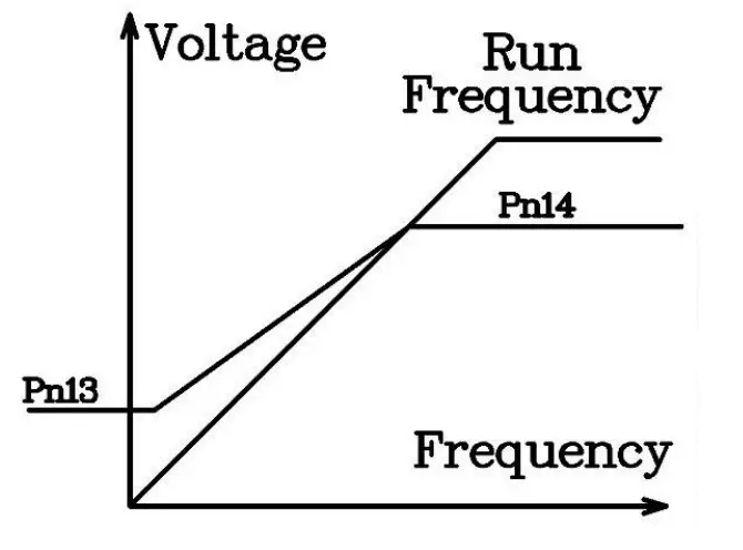
| Pn 13 | Torque compensation | 0.0-4.0 | 0.0 | 0.0 |
| Pn 14 | Torque compensation frequency | 0.01Hz-600.00Hz | 500Hz | 80Hz |
| Pn 15 | Startup DC braking voltage | 1V-100V | 30V | 30V |
| Pn 16 | Startup DC braking time | 000.00S-650.00S | OS | OS |
| Pn 17 | Stop DC braking voltage | 1V-100V | 30V | 30V |
| Pn 18 | Stop DC braking time | 000.00S-650.005 | OS | OS |
| Pn 19 | Source of multi-segment speed 0 | 1-5 | 1 | 1 |
| Pn 20 | Multi-segment speed 1 frequency | 000.10 Hz-400.00Hz | 10 | I 0 |
| Pn 21 | Multi-segment speed 2 frequency | 000.10 Hz-400.00Hz | 20 | 20 |
| Pn 22 | Multi-segment speed 3 frequency | 000.10 Hz-400.00Hz | 30 | 30 |
| Pn 23 | Multi-segment speed 4 frequency | 000.10 Hz-400.00Hz | 40 | 40 |
| Pn 24 | Multi-segment speed 5 frequency | 000.10 Hz— 400.00Hz | 50 | 50 |
| Pn 25 | Multi-segment speed 6 frequency | 000.10 Hz— 400.00Hz | 60 | 60 |
| Pn 26 | Multi-segment speed 7 frequency | 000.10 Hz— 400.00Hz | 70 | 70 |
| Pn 27 | Point move frequency | 000.10 Hz— 400.00Hz | 10Hz | 10Hz |
| Pn 28 | Choice of relay output | 1-6 | 3 | 3 |
| Pn 29 | 2rd acceleration time | 000.01S-650.00S | 2S | 2S |
| Pn 30 | 2rd deceleration time | 000.01S-650.00S | 2S | 2S |
| Pn 31 | 2rd deceleration stop frequency | 000.01Hz— 400.00Hz | 1Hz | 1Hz |
| Pn 32 | Parameter management | 1-6 | 1 | 1 |
| Pn 33 | Software version | 32029 | ***** | ***** |
| Pn 34 | Auto recovery while lost power suddenly | 0-99Hz | 0 | 0 |
| Pn 35 | Production date | * | ***** | ***** |
Please refer to Chapter 7 for a detailed description of each item
Remark: If over-voltage happens during deceleration, it will stop.
Note: If over-voltage happens during deceleration, the inverter will stop deceleration until the voltage goes back to a normal level. If better deceleration is needed, please switch to the inverter with braking.
Chapter 6 Description of Control Ports
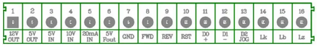
| Port name | Port Description |
| 12V OUT | 12V output, with maximum currency 200mA. |
| 5V OUT | 5V output, with maximum currency 50tnA. |
| 5V IN | 5V input, analog input, with maximum effective voltage 5V, no more than 6V |
| 10V IN | 10V input, analog input, with maximum effective voltage 10y, no more than 12V |
| 20mA IN | 20mA input, analog input, with maximum effective currency 20mA, no more than 25mA |
| 5V Fout | Frequency signal output, maximum output voltage 5V |
| GND | Power source ground OV. |
| FWD | External clockwise rotation input |
| REV | External anticlockwise rotation input |
| RST | External reset signal |
| DO + | Multi-segment speed DO input, external “+” signal means clockwise point move input |
| D1 – | Multi-segment speed DI input, external “-” signal means anticlockwise point move input |
| D2 JOG | Multi-segment speed D2 input, external enable signal input |
| Lk | Relay ON |
| Lb | Relay OFF |
| Lz | Relay ON/OFF |
Chapter 7 Description of Configure Parameters
 |  |
Pn 01
Default display content:1——30000
RUN: 1 means it will display runtime frequency
Otherwise, it displays the motor’s synchronization speed.
2——30000 is motor synchronization speed
STOP: it will display the frequency given by an external signal.
Pn 02
Initial startup frequency by a panel or another method
Range:000.01Hz-400.00Hz, the initial panel data, and external signal frequency during startup.
Chapter 8 Operation Examples
8.1 Operation by a panel
Pn 04 = 1(Command from panel) ,Pn 03 = 1(Frequency from potentiometer) 。
Push the button “RUN” on the panel, the inverter starts up and the running indicator is on.
Push the button again, the inverter would stop.
8.2 Operation by an external signal
Pn 04=2 (command from port “FWD/REV”)
Pn 03=3 (frequency from port “5V”)
8.3 Multi-segment speed
Pn 04=2(command from port “FWD/REV”)
Pn 03=7(frequency from multi-segment 0-7)
8.4 Point move by a panel
Command(Pn 04)must come from panel(=1 ). Frequency(Pn 03)must be
specified by button(=2. After the inverter stops, push the button “←” to the clockwise point move and “→” to the anticlockwise point move.
8.5 Point move by an external signal
Command(Pn 04)must come from port “FWD/REV”(=2 ). Frequency (Pn 03)must come from an external digital port (=6 ). After the inverter stops, connect “D0” and “JOG” to “GND” to point move clockwise, and connect “D1” and JOG” to “GND” to point move anticlockwise.
Chapter 9 Error Message and Fault Diagnosis
9.1 Fault table
| Display | Meaning | Cause | Diagnosis |
| OU -o | Overvoltage | Overvoltage of power source | Check voltage of the power source |
| OU -u | Acceleration overvoltage | Overvoltage of power source | Check voltage of the power source |
| OU -d | Deceleration overvoltage | Overvoltage of power source or large inertia | Overvoltage of power source, increase deceleration time, add brake components |
| OU -r | Steady-state Overvoltage | Overvoltage of power source | Check the voltage of the power source |
| LU -o | Stop state undervoltage | Undervoltage of power source | Check the voltage of the power source |
| LU-u | Acceleration Undervoltage | Undervoltage of power source, small acceleration time | Check the voltage of the power source, increase acceleration time |
| LU -d | Deceleration undervoltage | Undervoltage of power source | Check the voltage of the power source |
| LU -r | Steady-state Undervoltage | Undervoltage of power source or large inertia | Check the voltage of the power source, decrease the load |
| OC -o | Stop state over currency | Component fail, interference | Push “RESET”. The component fails if it happens again. |
| Display | Meaning | Cause | Diagnosis |
| OC —u | Acceleration overcurrency | Small acceleration time or component fail | Increase acceleration time |
| OC —d | Deceleration overcurrency | Small deceleration time or component fail | Increase deceleration time |
| OC —r | Steady-state overcurrency | overload or component fail | Check motor load |
| OT —o | Overheat while stop | High environment temperature or fail temperature sensor | Check whether air temperature is over 50, check the CZ55 connection |
| OT —u | Overheat while acceleration | High environment temperature, small acceleration time | Check whether air temperature is over 50, increase acceleration time |
| OT —d | Overheat while deceleration | High environment temperature, small deceleration time | Check whether the air temperature is over 50, increase the deceleration time |
| OT —r | Overheat in steady state | High environment temperature, overload | Check whether air temperature is over 50, and check for overload |
Chapter 10 Maintenance and Repair
Due to environmental influences such as temperature, humidity, dust, and vibration, etc., and aging components, the inverter may fail at some time. So it needs periodic maintenance and repair.
Notice: please check the following items before maintenance and repair. Otherwise, it may cause electronic shock.
- The power source is cut off.
- The indicator on the panel is OFF.
- Maintenance is performed by professionals.
10.1 Daily maintenance and repair
The Inverter must be installed in the standard environment according to this manual. There may be some unexpected situations during runtime. Please do daily maintenance work according to the following table. Keep a good runtime environment, log daily data and detect fault causes early. It can extend the life of the inverter.
| Item | Check | Criterion | ||
| Content | Period | Method | ||
| environment | (1)temperature, humidity (2)dust, water (3)corrosive gas | anytime | (1)thermometer, hygrometer (2)watch (3)smell | (1)temperature range -10°C — 1-40 t (2)any mark of water (3)odor |
| inverter | (1)heat, vibration (2)noise | anytime | (1)touch shell (2)sound | (1) steady vibration, normal temperature (2)abnormal sound |
| motor | (1)heat (2)noise | anytime | (1)touch (2)sound | (1)abnormal heating (2)abnormal sound |
Chapter 11 Type Description
11.1 Type Description
| A2 | is the VFD series, |
| xxxx | For power and voltage levels. |
| B | is Brake unit |


