EBYTE E108-D01 1 Multi Mode Satellite Positioning Terminal
Overview
Introduction
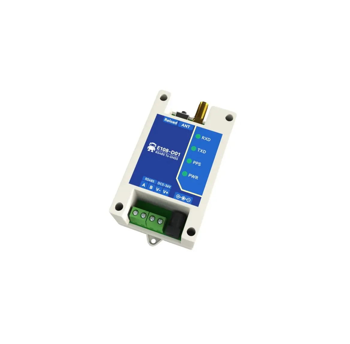
E108-D01 is a positioning terminal that supports multiple positioning systems (GPS, BDS, GLONASS, Galileo, etc.), with fast response and accurate positioning.
It outputs positioning information through the Modbus RTU protocol, supporting the output of RMC-ASCII strings conforming to the NMEA0183 protocol. It also supports separate registers to store (longitude, longitude direction, latitude, latitude direction, etc.), The baud rate of the serial port can reach up to 115200bps, which can be easily modified through the Modbus RTU protocol, convenient and fast.
Features
- Support single-system positioning of BDS/GPS/GLONASS/GALILEO/QZSS/SBAS satellite navigation system, and multi-system joint positioning in any combination;
- Multiple serial port baud rates (1200-115200bps) can be configured;
- Support standard Modbus RTU protocol to read positioning information;
- Multiple output formats for positioning information;
- The antenna positioning status is output through registers and indicator lights;
- The serial port supports TVS and overcurrent protection;
- Industrial grade design, support operating temperature up to -40 ~ 85 ℃;
- Support wide voltage input DC 5-36V;
- The positioning accuracy can reach 2.5 meters (CEP50);
Quick Start
Preparation
Take obtaining the REC positioning information output by the device as an example:
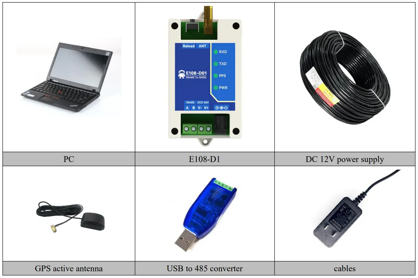
Hard wares preparation:
- A computer;
- E108-D1 positioning module;
- Active GPS antenna (SMA, inner thread, inner needle);
- One USB to RS-485 serial cable;
Software preparation:
- Serial port debugging tool (User can download the “XCOM” serial port debugging tool from Ebyte’s official website www.cdebyte.com);
Operation demonstration
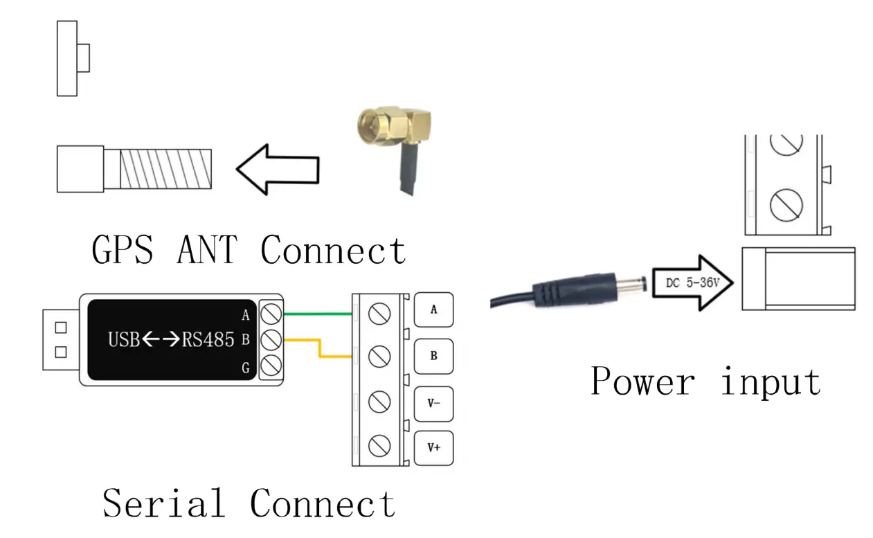
After preparing the above software and hardware, user can query the device positioning information and UTC time through the Modbus RTU command, correctly connect the device power supply and serial port, connect the antenna and move the antenna to an open space, as shown in the following figure:
Select the correct serial port number, adjust the baud rate parameter to 9600-8N1, and send the hexadecimal data.
“0x010300C800110438” to receive the device response data, as shown in the figure below.
If the response data cannot be received, please check whether the serial port is connected correctly, whether the parameter configuration is correct, whether to send hexadecimal data.
If all the configurations are correct, but no response received yet, pls press the button to restore the factory parameters and test again.
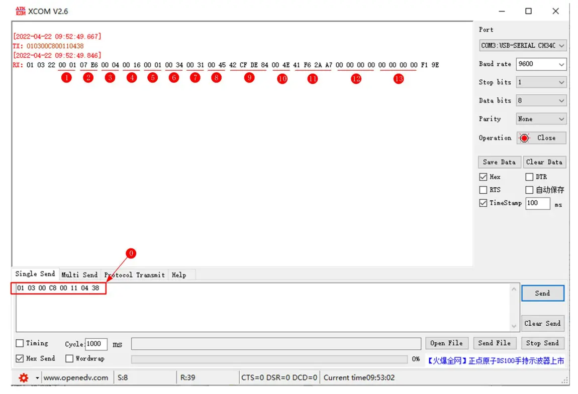
Data analysis table
| No. | Original Value (HEX) | Description | Conversion Rules | After Conversion |
| 1 | 0x00 00 | Positioning Effectiveness | 0x00:invalid 0x01:valid | valid |
| 2 | 0x07 e6 | year | HEXàDEC | 2022 |
| 3 | 0x00 04 | month | HEXàDEC | 4 |
| 4 | 0x00 16 | day | HEXàDEC | 22 |
| 5 | 0x00 01 | hour | HEXàDEC | 1 |
| 6 | 0x00 34 | minute | HEXàDEC | 34 |
| 7 | 0x00 31 | second | HEXàDEC | 31 |
| 8 | 0x00 45 | Longitude direction | Low level is valid, HEXàASCII | E |
| 9 | 0x42 cf de 84 | longitude | 32-bit floating point numbers, big endian-big endian | 103.93460083007812 |
| 10 | 0x00 4e | Latitude direction | Low level is valid, HEXàASCII | N |
| 11 | 0x4e f6 2a a7 | latitude | 32-bit floating point numbers, big endian-big endian | 30.77082633972168 |
| 12 | 0x00 00 00 00 | speed over ground | 32-bit floating point numbers, big endian-big endian | 0 |
| 13 | 0x00 00 00 00 | course over ground | 32-bit floating point numbers, big endian-big endian | 0 |
【Notes】:The time is UTC time.
Technical indicators
General Specifications
| No. | Item | Specifications |
| 1 | voltage | 5V~36V DC |
| 2 | Serial port spec. | Standard RS-485 interface |
| 3 | Baud rate | 4800-115200bps |
| 4 | Communication protocol | Modbus RTU |
| 5 | Position system supported | BDS/GPS/GLONASS/GALILEO/QZSS/SBAS |
| 6 | User configuration | Modify the register through Modbus RTU, restart to take effect |
| 7 | Antenna interface | SMA(External thread, inner hole) |
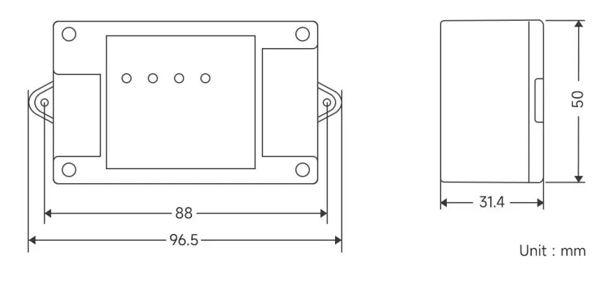
| 8 | Size | 96.5mm*50mm*31.4mm |
| 9 | Weight | 63± 5g |
| 10 | Working temperature | -40 ~ +85℃, industrial grade |
| 11 | Working humidity | 10% ~ 90%, Relative humidity, non-condensing |
GPS performance
| Category | Indicator item | Typical value | Unit |
| positioning time (Test Condition 1) | Cold start | 27.5 | S |
| Hot start | <1 | S | |
| Recapture | <1 | S | |
| A-GNSS | <10 | S | |
| Sensitivity (Test Condition 2) | Cold start | -148 | dBm |
| Hot start | -162 | dBm | |
| Recapture | -164 | dBm | |
| Track | -166 | dBm | |
| precision (Test Condition 3) | Horizontal positioning accuracy | 2.5 | m |
| High positioning accuracy | 3.5 | m | |
| Speed positioning accuracy | 0.1 | m/s | |
| Timing accuracy | 30 | ns | |
| Power consumption | Capture current | 30 | mA |
| (Test Condition 4) | Tracking current | 20 | mA |
| Working temperature | — | -35℃–85℃ | — |
| Storage temperature | — | -55℃–100℃ | — |
| Humidity | — | 5%–95%RH (non-condensing) | — |
【Notes】:The above results are GPS/BDS dual-mode working mode
[Test Condition 1]: More than 6 of receiving satellites, the signal strength of all satellites is -130dBm, the average value is obtained after 10 tests, and the positioning error is less than 10 meters.
[Test Condition 2]:The noise figure of the external LNA is 0.8, the number of receiving satellites is greater than 6, and the received signal strength value under the condition of locking within five minutes or not losing the lock.
[Test Condition 3]:Open and unobstructed environment, 24 hours of continuous power-on test, 50% CEP.
[Test Condition 4]: The number of receiving satellites is greater than 6, and the signal strength of all satellites is -130dBm.
Mechanical dimension drawing
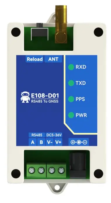
Pin and Indicator light Definitions
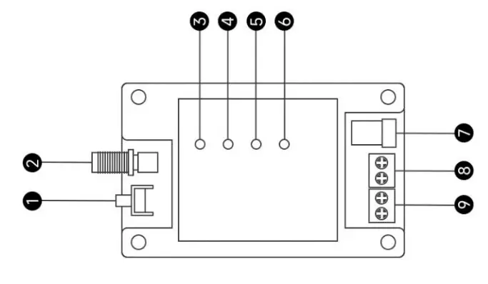
| No. | Identification name | Function description |
| 1 | Factory button | Long press for 5-10s is valid, and the device address and baud rate parameters are restored to the factory parameters; Factory parameters: the device address is 1, the serial port parameter is 9600/8/no parity/1 |
| 2 | ANT | SMA antenna interface, need to use GPS active antenna |
| 3 | RXD Indicator light | Receive indicator, flashes when receiving data from RS485 bus |
| 4 | TXD Indicator light | Transmitting indicator, flashes when transmitting data to RS485 bus |
| 5 | PPS Second pulse indicator | Steady on when the positioning is invalid; flashes once per second after the positioning is valid |
| 6 | PWR Indicator light | Power indicator, steady on when power on |
| 7 | DC_IN | Power interface, 5~36V DC female socket (inner needle diameter 2.0mm, hole diameter 6.4mm) |
| 8 | Power interface | 3.81mm phoenix terminal power input positive (top), power input negative (bottom), 5~36V DC, cannot supply power with socket at the same time |
| 9 | RS-485 interface | RS485 bus B (top), RS485 bus A (bottom) |
Modbus Register
Communication Protocol
The protocol layer of the GPS/BDS positioning module is a standard Modbus communication protocol, which conforms to the national standard GBT 19582.1-2008 “Industrial Automation Network Specification Based on Modbus Protocol”. It adopts the Modbus RTU communication protocol, and return data according to the parsing result by receiving and parsing the frame data on the data bus.
The frame format is as follows:
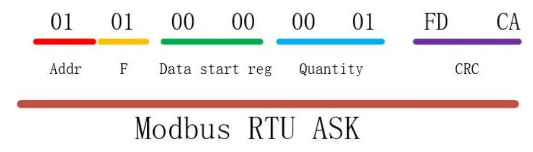
Register description
The following table describes the specific meaning of the decimal registers and the function codes used for operation.
| Register | Read function code (HEX) | Write function code (HEX) | Channel example |
| [Area 1] Discrete Input Register | 02 | —— | 10001, indicating the DI1 register address |
| [Area 0] Switch output register | 01 | 05 0F | 00001, indicating the DO1 register address |
| [Area 3] Input register | 04 | —— | 30001, means address 1 of zone 3 |
| [Area 4] Holding Registers | 03 | 06 10 | 40001, indicating address 1 of area 4 |
【Note】This device will only use the register address of zone 4 (that is, the holding register).
Register table
| Register Function | Register Address | Data Format | Data Range/Remarks | |
| (Decimal) | (Hex) | |||
| Version number | 40001 | 0001 | Int16 | The low byte is valid, where the upper 4 bits represent the major version number, and the lower 4 bits represent the minor version number. 0x0010 represents version 1.0. The version number is read-only. |
| Device address | 40002 | 0002 | Int16 | 1-255, default 1, support to read and modify broadcast address (0x00). |
| Baud rate | 40003 | 0003 | Int16 | Baud rate code: 0x0000:1200bps, 0x0001:2400bps, 0x0002:4800bps, 0x0003:9600bps, 0x0004:19200bps,0x0005:38400bps, 0x0006:57600bps,0x0007:115200bps, |
| Parity | 40004 | 0004 | Int16 | 0x0000:None parity, 0x0001:Odd parity, 0x0002:Even parity, Configuring other parameters does not take effect; |
| RMC-Location Data | 40005 | 0005 | String (70Btye) | Store 70 bytes of RMC-NMEA0183 protocol data, use ASCII encoding, and use AB in the decoding order; |
| … | … | … | … | Reserve; |
| Positioning status | 40200 | 00C8 | Int16 | 0:invalid positioning,1:valid positioning, read only; |
| Year | 40201 | 00C9 | Int16 | 2022 represents year 2022, read only; |
| Month | 40202 | 00CA | Int16 | The value range is 1 to 12, representing January to December respectively, read-only; |
| Day | 40203 | 00CB | Int16 | The value range is 1 to 31, representing 1st to 31st respectively, read-only; |
| Hour | 40204 | 00CC | Int16 | The value range is 0 to 23, representing 0 to 23 o’clock respectively, read-only; |
| Minute | 40205 | 00CD | Int16 | The value ranges from 0 to 59, representing 0 to 59 minutes respectively, read-only; |
| Second | 40206 | 00CE | Int16 | The value ranges from 0 to 59, representing 0 to 59 seconds respectively, read only; |
| Longitude direction | 40207 | 00CF | Int16 | 0x45(ASCII:E) represents the East longitude, 0x57(ASCII:W) represents the West longitude; |
| Longitude | 40208 | 00D0 | Float (4Byte) | The unit is degrees, 5 decimal places after the decimal point, read only Example: 103.93416°, word order: big endian, byte order: big endian; |
| Latitude direction | 40210 | 00D2 | Int16 | 0x4E(ASCII : N) Represents North latitude, read only 0x53(ASCII:S) Represents South latitude |
| Latitude | 40211 | 00D3 | Float (4Byte) | The unit is degrees, 5 decimal places after the decimal point, read only Example: 30.77056°, word |
| order: big endian, byte order: big endian; | ||||
| Speed over ground | 40213 | 00D5 | Float (4Byte) | The unit is Kn, read-only, word order: big endian, byte order: big endian; |
| Course over ground | 40215 | 00D7 | Float (4Byte) | The unit is Kn, read-only, word order: big endian, byte order: big endian; |
Use of Modbus RTU
[Note] In the following demo, the device address is 1. If using a different device address, then the address bits and checking code are different from below values.
Holding Registers
The register used by E108-D01 is holding register. The function code for writing the holding register is 0x06 (write a single holding register), and reading the holding register uses 0x03 (reading the holding register)
0x03 code read instruction format (take the read version as an example):
| Device address | Function code | First address | Read quantity | Check code CRC |
| 01 | 03 | 00 01 | 00 01 | D5 CA |
Return format (take the read version as an example):
| Device address | Function code | Data length | Read quantity | Check code CRC |
| 01 | 03 | 02 | 00 10 | B9 88 |
0x06 code configuration command format (configure device address as an example):
| Device address | Function code | Data length | Value | Check code CRC |
| 01 | 03 | 00 02 | 00 01 | 25 CA |
Return format (configured device address as an example): the same as the command format;
Read Holding Register Instruction
Read version number
Command frame: 01 03 00 01 00 01 D5 CA
| Address | Function code | Register start address | Number of registers | CRC check |
| 0x01 | 0x03 | 0x00 0x01 | 0x00 0x01 | 0xD5 0xCA |
Response frame: 01 03 02 00 10 B9 88
| Address | Function code | Data length | data | CRC check |
| 0x01 | 0x03 | 0x02 | 0x00 0x10 | 0xB9 0x88 |
Note:
The version number in the returned data is 0x0010, indicating that the version number is V1.0.
Read device address (broadcast)
Command frame: 00 03 00 02 00 01 24 1B
| Address | Function code | Register start address | Number of registers | CRC check |
| 0x00 | 0x03 | 0x00 0x02 | 0x00 0x01 | 0x24 0x1B |
Response frame: 00 03 02 00 01 44 44
| Address | Function code | Data length | data | CRC check |
| 0x00 | 0x03 | 0x02 | 0x00 0x01 | 0x44 0x44 |
[Note] This command is a general read command of the address. When using the broadcast command, to avoid conflicts with other devices in the system, please ensure that only the device to be read is connected to the bus when reading.
Read device baud rate
Command frame: 01 03 00 03 00 01 74 0A
| Address | Function code | Register start address | Number of registers | CRC check |
| 0x01 | 0x03 | 0x00 0x03 | 0x00 0x01 | 0x74 0x0A |
Response frame: 01 03 02 00 03 F8 45
| Address | Function code | Data length | data | CRC check |
| 0x01 | 0x03 | 0x02 | 0x00 0x03 | 0xF8 0x45 |
Note:
The returned baud rate is 0x03, which means 9600 bps. For other baud rate codes, see the description of “Modbus register table”.
Read parity
Command frame: 01 03 00 04 00 01 C5 C8
| Address | Function code | Register start address | Number of registers | CRC check |
| 0x01 | 0x03 | 0x00 0x04 | 0x00 0x01 | 0xC5 0xC8 |
Response frame: 01 03 02 00 00 B8 44
| Address | Function code | Data length | data | CRC check |
| 0x01 | 0x03 | 0x02 | 0x00 0x00 | 0xB8 0x44 |
Note: The return check digit is 0x00, which means no parity check. See the description of “Modbus register table” for other check codes.
Read positioning data (RMC)
Command frame: 01 03 00 05 00 23 14 12
| Address | Function code | Register start address | Number of registers | CRC check |
| 0x01 | 0x03 | 0x00 0x05 | 0x00 0x23 | 0x14 0x12 |
Response frame:
| Address | Function code | Data length | data | CRC check |
| 0x01 | 0x03 | 0x46 | 70byte data | 2byte check |
Positioning data (RMC) parsing
The 70-byte data returned by reading the positioning data (RMC) conforms to the NMEA0183 protocol, and the
ASCII display is as follows:
$GNRMC,083429.00,A,3046.26769,N,10356.04948,E,000.00,089.80,190422*21
| Field | Symbol | Meaning | Value Range | Example | Remarks |
| 1 | $ | ||||
| 2 | GNRMC | RMC protocol header, GNRMC means joint positioning | |||
| 3 | hhmmss.ss | UTC time | hhmmss.ss | 072905.00 | Plus 8h for Beijing East Eighth District needs |
| 4 | A | Positioning status | A/V | A-valid, V-invalid | |
| 5 | ddmm.mmmmm | Latitude | ddmm.mmmmm | 3640.46260 | Convert to degrees when calculating: 36 degrees + 40.46260 minutes. 40.46260/60=0.67438 degree, so the value 3640.46260 should be 36.67438 degree |
| 6 | a | Latitude direction | N/S | N-North latitude, S-South latitude | |
| 7 | ddmm.mmmmm | Longitude | ddmm.mmmmm | 3640.46260 | Convert to degrees when calculating: 36 degrees + 40.46260 minutes. 40.46260/60=0.67438 degree, so the value |
| 3640.46260 should be 36.67438 degree | |||||
| 8 | a | Longitude direction | E/W | E-East longitude, W-West longitude | |
| 9 | xxx.xx-xxx.xx | Speed over ground | Knot | 123.2 | Ground speed, unit Kn, range 000.00 to 999.99 knots, zero if the leading digit is insufficient |
| 10 | xxx.xx-xxx.xx | Course over ground | degree | 000.0~359.9 | Ground heading (000.00~359.99 degrees, with true north as the reference), zero if the leading digit is insufficient |
| 11 | xxxxxx | date | DDMMYY | 190422 | Apr.19, 2022 |
| 13 | * | statement terminator | |||
| 14 | 24 | checksum | XOR the data between ‘$’ and ‘*’ (excluding these two characters) by byte, expressed as a hexadecimal value | ||
Write Holding Register Instructions
Modify device address (broadcast)
[Note]This command is a general read command of the address. When using the broadcast command, to avoid conflicts with other devices in the system, please ensure that only the device to be read is connected to the bus when reading.
Command frame: 00 06 00 02 00 01 E8 1B
| Address | Function code | Register start address | Number of registers | CRC check |
| 0x00 | 0x06 | 0x00 0x02 | 0x00 0x01 | 0xE8 0x1B |
Response frame: 00 06 00 02 00 01 E8 1B
| Address | Function code | Register start address | Number of registers | CRC check |
| 0x01 | 0x06 | 0x00 0x02 | 0x00 0x01 | 0xE8 0x1B |
Note:
This command is used to set the device address, use 0x00 as the broadcast address, and modify the device address to 0x01.
Modify baud rate
Command frame: 01 06 00 03 00 03 39 CB
| Address | Function code | Register start address | Number of registers | CRC check |
| 0x01 | 0x06 | 0x00 0x03 | 0x00 0x03 | 0x39 0xCB |
Response frame: 01 06 00 03 00 03 39 CB
| Address | Function code | Register start address | Number of registers | CRC check |
| 0x01 | 0x06 | 0x00 0x03 | 0x00 0x03 | 0x39 0xCB |
Note:
This command is used to set the baud rate of the device to 9600.
The device defaults to 9600 baud rate without verification when it leaves the factory. Users can set the baud rate and verification method according to actual needs.
Modify the parity
Command frame: 01 06 00 06 00 04 09 CB
| Address | Function code | Register start address | Number of registers | CRC check |
| 0x01 | 0x06 | 0x00 0x06 | 0x00 0x04 | 0x09 0xCB |
Response frame: 01 06 00 06 00 04 09 CB
| Address | Function code | Register start address | Number of registers | CRC check |
| 0x01 | 0x06 | 0x00 0x06 | 0x00 0x04 | 0x09 0xCB |
Note:
This command is used to set the parity bit of the device to odd parity.
The final interpretation right belongs to Chengdu Ebyte Electronic Technology Co., Ltd.
Revise history
| Version | Revise date | Revise instruction | Issued by |
| 1.0 | 2022-05-05 | Initial version | LC |
| 1.1 | 2022-05-31 | Content revision | XXN |
About us
Technical support: [email protected]
Documents and RF Setting download link: www.cdebyte.com
Thank you for using Ebyte products! Please contact us with any questions or suggestions: [email protected]