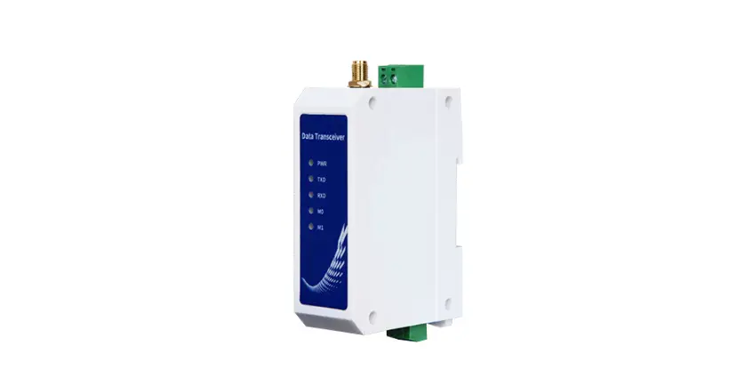
EBYTE E95-DTU 400SL30P-232 Wireless Modem
Disclaimer
EBYTE reserves all rights to this document and the information contained herein. Products, names, logos and designs described herein may in whole or in part be subject to intellectual property rights. Reproduction, use, modification or disclosure to third parties of this document or any part thereof without the express permission of EBYTE is strictly prohibited.The information contained herein is provided “as is” and EBYTE assumes no liability for the use of the information. No warranty, either express or implied, is given, including but not limited, with respect to the accuracy, correctness, reliability and fitness for a particular purpose of the information. This document may be revised by EBYTE at any time. For most recent documents, visit www.ebyte.com
Brief Introduction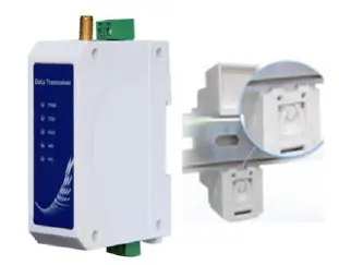
E95-DTU (400SL30P-232) is a wireless data transmission radio station that adopts military-grade LoRa modulation technology. It has a variety of transmission methods. It works in the frequency band (410.125MHz~ 493.125MHz) (default 433.125MHz). The radio provides a transparent RS232interface. Adopt plastic shell, guide rail type installation structure, support DC 8~28V voltage input. LoRa spread spectrum technology will bring longer communication distance, and has the advantage of strong anti-interference ability. As a communication medium, wireless data transmission station has a certain scope of application like optical fiber, microwave, and open wire: it provides real-time and reliable data transmission of monitoring signals in private networks under certain special conditions, with low cost, installation and maintenance Convenience, strong diffraction ability, flexible network structure, and long coverage. It is suitable for many and scattered locations and complex geographic environments. It can be connected with PLC, RTU, rain gauge, level gauge and other data terminals.
Features
- The latest LoRa technology is adopted, which is farther than traditional LoRa digital radio stations and has more powerful performance;
- With data encryption, the packet length can be set;
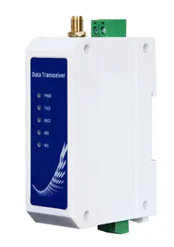
- Adopt flame-retardant plastic shell and guide rail type installation structure, which is convenient and efficient to install
- Hidden buttons are used to switch working modes to avoid false triggers, and the equipment is more reliable in operation;
- Simple high-efficiency power supply design, support power supply configuration or line pressure mode, support DC 8~28V power supply;
- The transmit power is up to30dBm, and supports multi-level adjustment, and all technical indicators meet industrial standards;
- Support Modbus protocol transmission;
- Support LBT function, the radio station automatically waits for transmission according to the current environmental noise intensity. Greatly improve the communication success rate of the radio station in harsh environments;
- Support wireless sending of command data packets, remote configuration or reading radio station parameters;
- Support communication key function, effectively prevent data from being intercepted;
- Multi-level relay networking can be realized, effectively extending the communication distance, and realizing ultra-long-distance communication;
- Using temperature compensation circuit, the frequency stability is better than ±1.5PPM;
- Operating temperature range: -40℃~ +85℃, adapt to various harsh working environments, real industrial grade products;
- Multiple protection functions such as power reverse connection protection, over-connection protection, antenna surge protection, etc., greatly increase the reliability of the radio;
- The communication port and power interface adopt isolation and high protection;
- Powerful software function, all parameters can be set by programming: such as power, frequency, air speed, address ID, etc.;
- Built-in watchdog, and accurate time layout, once an abnormality occurs, the radio will automatically restart, and can continue to work according to the previous parameter settings.
Quick Start
You need to prepare two E95-DTU (400SL30P-232)
First install the antenna for the digital radio, and then install the power supply. The user selects the power adapter for power supply according to the needs.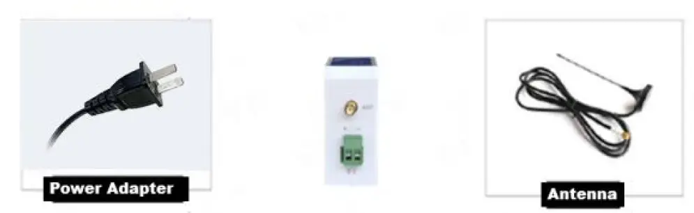
Use USB to RS232 or other methods to connect the computer to the digital radio;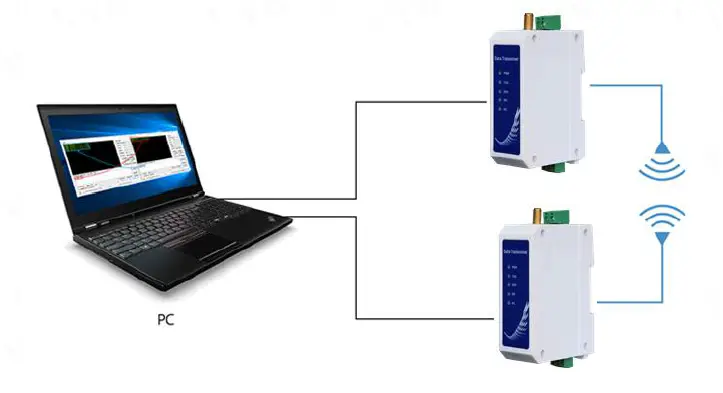
Start two serial port debugging assistants, select the serial port baud rate to be 9600bps (default), and the check method to be 8N1 to realize serial port transparent transmission;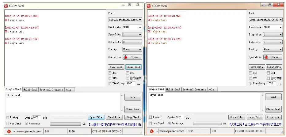
If the customer needs to switch the working mode, it can be controlled by the Mode button to switch between different working modes (M0 indicator, M1 indicator). Long press the Mode button for about 1ms and then release it to switch the mode once. The mode switching details are shown in the table below:\
| Serial number | Class | M1 | M0 | Note |
| mode 1 | Transparent transmission mode | Lights off | Lights off | Serial port open, wireless open, transparent transmission (factory default mode), support special command air configuration. |
| mode 2 | WOR mode | Lights off | Light on | Can be defined as WOR sender and WOR receiver, support air wakeup |
| mode 3 | Configuration mode | Light on | Lights off | The user accesses the register through the serial port to control the working status of the radio station. The user can configure the radio station through the upper computer configuration software. |
| mode 4 | Sleep mode | Light on | Light on | The radio goes to sleep |
Note: The radio has a power-down save mode function (the factory default setting is transparent transmission mode), and the user needs to switch the corresponding mode according to the M1 and M0 indicators (effective immediately).
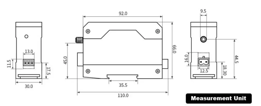
Installation Dimensions
Technical Index
General Specifications
| Serial number | Item | Specification | Note |
| 1 | Product Size | 92*66*30 mm | See installation dimensions for details |
| 2 | product weight | 95 g | Weight tolerance 5g |
| 3 | Operating temperature | -40℃~+85℃ | Industrial grade |
| 4 | voltage range | dC 8~28V | It is recommended to use 12V or 24V for DC |
| 5 | Communication | RS232 | RS232 |
| 6 | Baud rate | Factory default 9600 | Baud rate range 1200~115200 |
| 7 | address code | Factory default 0 | A total of 65536 address codes can be set |
Frequency Range and Number of Channels
| Product Model | Default frequency (MHz) | Frequency Range (MHz) | Channel spacing (MHz) | Number of channels |
| E95-DTU(400SL22P-485) | 433.125M | 410.125~493.125M | 1M | 84, Half duplex |
Note: If multiple groups of digital radios are used in the same area to communicate one to one at the same time, it is recommended that each group of digital radios set a channel spacing of more than 2MHz.
Transmit Power Level
| Product Model | 30dBm | 17dBm | 13dBm | 10dBm / 21dBm |
| E95-DTU(400SL22P-485) | Factory default | √ | √ | √ |
Note: The lower the transmission power, the closer the transmission distance, but the working current will not decrease in the same proportion. It is recommended to use the maximum transmission power.
AirSpeed Class
| Product Model | Default air rate(bps) | Number of levels | Air speed class(kbps) |
| E95-DTU(400SL22P-485) | Factory default | 8 | 0.3\1.2\2.4\4.8\9.6\19.2\38.4\62.5 |
Note: The higher the air speed setting, the faster the transmission rate and the shorter the transmission distance; therefore, when the speed meets the requirements of use, it is recommended that the airspeed be as low as possible.
Sending and Receiving Length and Subcontracting Method
| Product Model | Cache size | Subcontracting method |
| E95-DTU(400SL22P-485) | 1000 bytes | Can be set by instructions to sub-package 32/64/128/240 bytes to send |
Note:
- If the radio’s single received data is greater than the single packet capacity, the excess data will be automatically allocated to the second transmission until the transmission is completed;
- The single received data of the radio station cannot be larger than the buffer capacity.
Detailed Function
Fixed-point Transmission (Hexadecimal)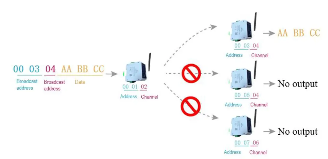
Broadcast Transmission (Hexadecimal) 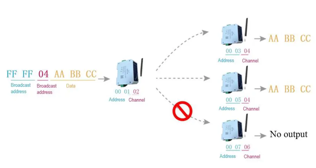
Broadcast Address
- Example: Set the address of station A to 0xFFFF and the channel to 0x04.
- When station A is used as a transmitter (same mode, transparent transmission mode), all receiving stations under the 0x04 channel can receive data to achieve the purpose of broadcasting.
Listening Address
- Example: Set the address of station A to 0xFFFF and the channel to 0x04.
- When the station A is receiving, it can receive all the data under the 0x04 channel to achieve the purpose of monitoring.
Product selection
E95-DTU has four working modes. When there is no demanding low power consumption, it is recommended to configure the radio to transparent transmission mode (mode 0) if normal communication is required. The default setting of the radio at the factory is transparent transmission mode (mode 0).
| Serial number | Category | M1 | M0 | Annotation |
| Mode 0 | Transparent transmission mode | Lights off | Lights off | Serial port open, wireless open, transparent transmission (factory default mode), support |
| special command air configuration. | ||||
| Mode 1 | WOR mode | Lights off | Light on | Can be defined as WOR sender and WOR receiver, support air wakeup |
|
Mode 2 |
Configuration mode |
Light on |
Lights off | The user accesses the register through the serial port to control the working status of the radio station. The user can configure the radio station through the upper computer configuration software. |
| Mode 3 | Deep sleep mode | Light on | Light on | The radio goes to sleep |
Transparent Transmission Mode (Mode 0)
| Type | When the M0 indicator light is off and the M1 indicator light is off, the radio is working in mode 0 |
| Emission | The user can input data through the serial port, and the radio will start wireless transmission. |
| Receive | The radio receiving function is turned on, and the wireless data will be output through the serial port TXD pin after receiving the wireless data. |
WOR Mode (Mode 1)
| Type | When the M0 indicator light is off and the M1 indicator light is off, the radio is working in mode 1 |
| Emission | When defined as the transmitter, the wake-up code for a certain period of time will be automatically added before transmission |
| Receive | Data can be received normally, the receiving function is equivalent to mode 0 |
Configuration Mode (Mode 2)
| Type | When the M0 indicator light is off and the M1 indicator light is on, the radio is working in mode 2 |
| Emission | Can be configured wirelessly |
| Receive | Can be configured wirelessly |
| Configurat ion | The user can access the register to configure the working status of the radio |
Deep Sleep Mode (Mode 3)
| Type | When the M0 indicator light is on and the M1 indicator light is on, the radio is working in mode 3 |
| Emission | Unable to transmit wireless data. |
| Receive | Cannot receive wireless data. |
Register Read and Write Control
Instruction Format
In configuration mode (mode 2: M1 indicator light is on, M0 indicator light is off), the supported command list is as follows (when setting, only 9600, 8N1 format is supported):
| Serial number | Instruction format | Detailed description |
|
1 | Set register | Command: C0+start address+length+parameter Response: C1+start address+length+parameter
Example 1: Configure the channel as 0x09 Instruction start address length parameter Send: C0 05 01 09 Returns: C1 05 01 09
Example 2: Configure the radio address (0x1234), network address (0x00), serial port (9600 8N1), airspeed (1.2K) at the same time Send: C0 00 04 12 34 00 61 Return: C1 00 04 12 34 00 61 |
|
2 | Read register | Command: C1+start address+length Response: C1+start address+length+parameter
Example 1: Read the channel Instruction start address length parameter Send: C1 05 01 Returns: C1 05 01 09 Example 2: Read the radio address, network address, serial port, airspeed at the same time Send: C1 00 04 Return: C1 00 04 12 34 00 61 |
|
3 | Set up temporary registers | Command: C2 + start address + length + parameters Response: C1 + start address + length + parameters
Example 1: Configure the channel as 0x09 Instruction start address length parameter Send: C2 05 01 09 Returns: C1 05 01 09
Example 2: Configure the radio address (0x1234), network address (0x00), serial port (9600 8N1), airspeed (1.2K) at the same time Send: C2 00 04 12 34 00 61 Return: C1 00 04 12 34 00 61 |
|
5 | Wireless configuration | Instructions: CF CF + regular instructions Response: CF CF + regular response
Example 1: The wireless configuration channel is 0x09 Wireless command header command start address length parameter Send: CF CF C0 05 01 09 Returns: CF CF C1 05 01 09
Example 2: Wirelessly configure the radio address (0x1234), network address (0x00), serial port (9600 8N1), airspeed (1.2K) at the same time Send: CF CF C0 00 04 12 34 00 61 Return: CF CF C1 00 04 12 34 00 61 |
| 6 | wrong format | Malformed response FF FF FF |
Register Description
| Serial number | Read and write | name | description | Remarks |
| 00H | Read/ Write | ADDH | ADDH(Default 0) | High byte and low byte of radio address; Note: When the radio station address is equal to FFFF, it can be used as the broadcast and monitor address, that is: the radio station will not perform address filtering at this time |
|
01H | Read/ Write |
ADDL |
ADDL(Default 0) | |
|
02H | Read/ Write |
NETID |
NETID(Default 0) | Network address, used to distinguish networks; When communicating with each other, they should be set to the same. |
|
03H |
Read/ Write |
REG0 | 7 | 6 | 5 | UART Serial port rate (bps) | For two radios that communicate with each other, the serial port baud rate can be different, and the verification method can also be different;
When continuously transmitting large data packets, users need to consider the data congestion caused by the same baud rate, and may even be lost;
It is generally recommended that the baud rate of the two communication parties be the same. |
| 0 | 0 | 0 | Serial port baud rate1200 | ||||
| 0 | 0 | 1 | Serial port baud rate2400 | ||||
| 0 | 1 | 0 | Serial port baud rate4800 | ||||
| 0 | 1 | 1 | Serial port baud rate9600 (Default) | ||||
| 1 | 0 | 0 | Serial port baud rate19200 | ||||
| 1 | 0 | 1 | Serial port baud rate38400 | ||||
| 1 | 1 | 0 | Serial port baud rate57600 | ||||
|
1 |
1 |
1 |
Serial port baud rate115200 | ||||
| 4 | 3 | Serial port check digit |
The serial port mode of the two communication parties can be different; | ||||
| 0 | 0 | 8N1(Default) | |||||
| 0 | 1 | 8O1 | |||||
| 1 | 0 | 8E1 | |||||
| 1 | 1 | 8N1 (equivalent to 00) | |||||
| 2 | 1 | 0 | Wireless air rate (bps) |
The air rate of both parties must be the same
The higher the air rate, the smaller the delay and the shorter the transmission distance. | |||
| 0 | 0 | 0 | Air speed0.3k | ||||
| 0 | 0 | 1 | Air speed1.2k | ||||
| 0 | 1 | 0 | Air speed2.4k(Default) | ||||
| 0 | 1 | 1 | Air speed4.8k | ||||
| 1 | 0 | 0 | Air speed9.6k | ||||
| 1 | 0 | 1 | Air speed19.2k | ||||
| 1 | 1 | 0 | Air speed38.4k | ||||
| 1 | 1 | 1 | Air speed62.5k | ||||
|
04H |
Read/ Write |
REG1 | 7 | 6 | Subcontracting settings | The data sent by the user is less than the sub-packet length, and the serial port output of the receiving end appears as an uninterrupted continuous output;
If the data sent by the user is larger than the packet length, the serial port of the receiving end will output in packets. | |
| 0 | 0 | 240byte(Default) | |||||
| 0 | 1 | 128byte | |||||
| 1 | 0 | 64byte | |||||
| 1 | 1 | 32byte | |||||
| 5 | RSSI Environmental noise enable | After enabling, you can send commands C0 C1 C2 C3 in transmission mode or WOR sending mode to read registers; Register 0x00: Current environmental noise RSSI; Register 0X01: RSSI when receiving data last time (The current channel noise is: dBm =-RSSI/2); Instruction format: C0 C1 C2 C3 + start address + read length; Return: C1 + address address + read length + read valid value; for example: | |||||
| 0 | Disabled (default) | ||||||
|
1 |
Enable | ||||||
| send C0 C1 C2 C3 00 01 Return C1 00 01 RSSI | ||||||||
| 4 | 3 | 2 | Keep | |||||
| 1 | 0 | Transmit power | The relationship between power and current is non-linear. At the maximum power, the power supply has the highest efficiency; the current will not decrease in the same proportion as the power decreases. | |||||
| 0 | 0 | 30dBm(default) | ||||||
| 0 | 1 | 17dBm | ||||||
| 1 | 0 | 13dBm | ||||||
| 1 | 1 | 10dBm / 21dBm | ||||||
| 05H | Read/ Write | REG2 | Channel Control (CH) 0-83 respectively represent a total of 84 channels | Actual frequency = 410.125 + CH *1M | ||||
|
06H |
Read/ Write |
REG3 | 7 | zEnable RSSI byte | After being enabled, the radio receives wireless data and outputs it through the serial port TXD, followed by an RSSI strength byte. | |||
| 0 | Disabled (default) | |||||||
| 1 | Enable | |||||||
| 6 | transfer method | During fixed-point transmission, the radio will recognize the three bytes of serial data as: address high + address low + channel, and use it as a wireless transmission target. | ||||||
| 0 | Transparent transmission (default) | |||||||
| 1 | Fixed-point transmission | |||||||
| 5 | Relay function | After the relay function is enabled, if the target address is not the radio station itself, the radio station will start a forwarding; In order to prevent data return, it is recommended to use it in conjunction with the fixed-point mode; that is, the destination address and the source address are different. | ||||||
| 0 | Disable relay function (default) | |||||||
|
1 | Enable relay function | |||||||
| 4 | LBT enable | After enabling, the wireless data will be monitored before transmission, which can avoid interference to a certain extent, but it may cause data delay;
The maximum stay time of LBT is 2 seconds, and it will be issued forcibly when it reaches 2 seconds. | ||||||
| 0 | Disabled (default) | |||||||
|
1 | Enable | |||||||
| 3 | WOR mode transceiver control | Only valid for mode 1;
After the WOR receiver receives the wireless data and outputs it through the serial port, it will wait 1000ms before entering the WOR again. During this period, the user can input the serial data and return it wirelessly;
Each serial port byte will be refreshed for 1000ms;
The user must initiate the first byte within 1000ms. | ||||||
|
0 | WOR receiver (default) The radio transceiver is turned on, and when transmitting data, a wake-up code for a certain period of time is added. | |||||||
|
1 | WOR transmitter The radio cannot transmit data and works in WOR monitoring mode. The monitoring period is shown below (WOR period), which can save a lot of power consumption. | |||||||
| 2 | 1 | 0 | WOR cycle | Only valid for mode 1; | ||||
| 0 | 0 | 0 | 500ms | Cycle T= (1+WOR)*500ms, the maximum is 4000ms, the minimum is 500ms;
The longer the WOR monitoring interval period, the lower the average power consumption, but the greater the data delay;
Both sender and receiver must agree (very important) | |||
| 0 | 0 | 1 | 1000ms | ||||
| 0 | 1 | 0 | 1500ms | ||||
| 0 | 1 | 1 | 2000ms | ||||
| 1 | 0 | 0 | 2500ms | ||||
| 1 | 0 | 1 | 3000ms | ||||
| 1 | 1 | 0 | 3500ms | ||||
| 1 | 1 | 1 | 4000ms | ||||
| 07H | Write | CRYPT _H | High byte of key (default 0) | Only write, read returns 0; Used for encryption to avoid interception of wireless data in the air by similar radio stations; The radio station will use these two bytes as a calculation factor to transform and encrypt the wireless signal in the air. | |||
|
08H |
Write |
CRYPT _L | Low byte of key (default 0) | ||||
| 80H~ 86H | Read | PID | Product information 7 bytes | Product information 7 bytes | |||
Factory Default Parameters
| Product model | Factory default parameter value:C0 00 00 62 00 00 | ||||||
| Radio model | Frequency | Address | Channel | Air rate | Baud rate | Serial format | Transmit power |
| E95-DTU(400SL22P-48 5) | 433.125M Hz | 0x0000 | 0x17 | 2.4kbps | 9600 | 8N1 | 30dBm (small power) |
Relay Networking Mode Use
| Serial number | Relay mode description |
| 1 | After setting the relay mode through the configuration mode, switch to the normal mode, and the relay starts to work. |
| 2 | In the relay mode, ADDH and ADDL are no longer used as the radio address, but correspond to the NETID forwarding pairing respectively. If one of the networks is received, it will be forwarded to the other network. The network ID of the repeater itself is invalid. |
| 3 | In the relay mode, the relay station cannot send and receive data, and cannot perform low-power operation. |
| 4 | When the user enters other modes from Mode 3 (sleep mode) or is in the reset process, the radio will reset the user parameters, during which AUX outputs low level. |
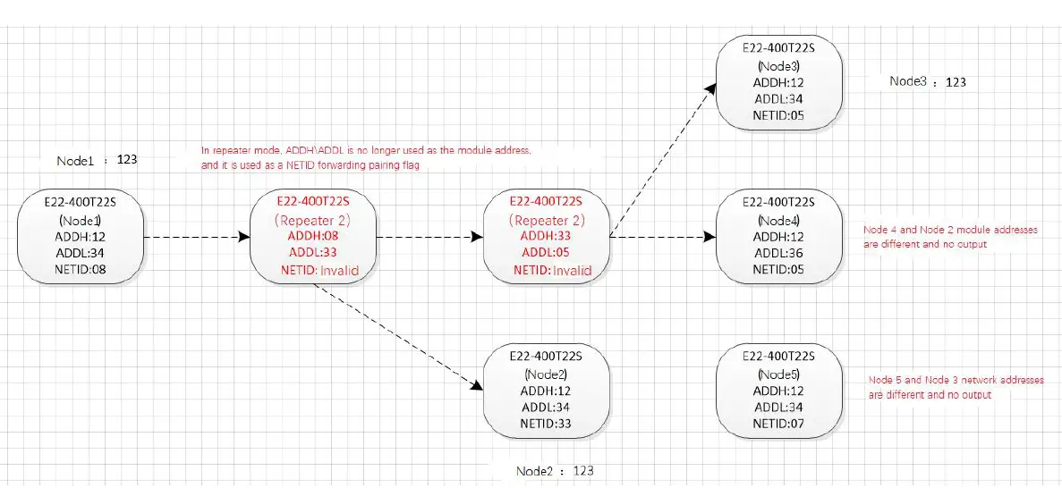
- Forwarding rules, the relay can forward data in both directions between two NETIDs.
- In the relay mode, ADDH\ADDL is no longer used as a radio address, but as a NETID forwarding pairing. As shown in the figure:
① First level relay
“Node 1” NETID is 08.
“Node 2” NETID is 33.
The ADDH\ADDL of relay 1 are 08 and 33 respectively.
So the signal sent by node 1 (08) can be forwarded to node 2 (33)
At the same time, node 1 and node 2 have the same address, so the data sent by node 1 can be received by node 2.
② Secondary relay
The ADDH\ADDL of relay 2 are 33 and 05 respectively.
So relay 2 can forward the data of relay 1 to the network NETID: 05.
Therefore, node 3 and node 4 can receive node 1 data. Node 4 normally outputs data, and node 3 has a different address from node 1, so no data is output.
③ Two-way relay
As shown in the configuration: the data sent by node 1 can be received by nodes 2 and 4, and the data sent by nodes 2 and 4 can also be received by node
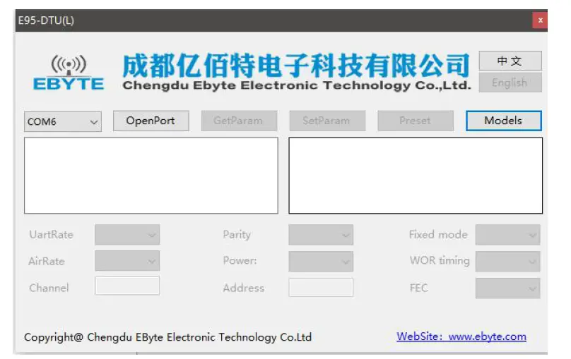
Relay Networking Mode Use
- The following figure shows the display interface of the E95-DTU (400SL30P-232) configuration host computer. The user can switch to the configuration mode through the MODE button, and quickly configure and read the parameters on the host computer.

- In the configuration of the host computer, the radio address, frequency channel, network ID, and key are all displayed in decimal mode. The range of each parameter is:
Network address: 0~65535
Frequency channel: 0~83
Network ID: 0~255
Key: 0~65535 - When using the host computer to configure the relay mode, the user needs to pay special attention. Since the parameters in the host computer are in decimal display mode, the radio address and network ID need to be converted when filling in the radio station address and network ID. If the network ID input by the transmitting terminal A is 02 and the network ID input by the receiving terminal B is 10, when the relay terminal R sets the radio address, the hexadecimal value 0X020A is converted to the decimal value 522 as the relay terminal R. Radio address. That is, the radio address value that needs to be filled in by the relay terminal R at this time is 522.
Program the Radio
| Operating mode | M1 | M0 | 注释 |
| Configuration mode | The indicator light is on | The indicator light is off | Only use the configuration software to program the radio in the current mode |
- Programming can only be carried out in a specific working mode (see the above table). If the programming fails, please confirm whether the working mode of the radio is correct.
- If you don’t need complicated programming to open the E95-DTU (400SL30P-232) configuration software, you can modify the relevant parameters.
|
Product Number | Interface Type | Working Frequency MHz | Transmit Power dBm | Commu nication Distanc e km |
Features |
| E95-DTU(400SL22-485) | RS485 | 410.125 ~ 493.125 | 22 | 5 | A new generation of LoRa, rail type, RS485, E90-DTU SL series intercommunication, DC power supply |
| E95-DTU(400SL22-232) | RS232 | 410.125 ~ 493.125 | 22 | 5 | A new generation of LoRa, rail type, RS232, E90-DTU SL series intercommunication, DC power supply |
| E95-DTU(400SL30-485) | RS485 | 410.125 ~ 493.125 | 30 | 10 | A new generation of LoRa, rail type, RS485, E90-DTU SL series intercommunication, DC power supply |
| E95-DTU(400SL30-232) | RS232 | 410.125 ~ 493.125 | 30 | 10 | A new generation of LoRa, rail type, RS232, E90-DTU SL series intercommunication, DC power supply |
| E95-DTU(400SL22P-485 ) |
RS485 |
410.125 ~ 493.125 |
22 |
5 | A new generation of LoRa, rail type, RS485, E90-DTU SL series intercommunication, high protection, DC power supply |
| E95-DTU(400SL22P-232 ) |
RS232 |
410.125 ~ 493.125 |
22 |
5 | A new generation of LoRa, rail type, RS232, E90-DTU L series intercommunication, high protection, DC power supply |
| E95-DTU(400SL30P-485 ) |
RS485 |
410.125 ~ 493.125 |
30 |
10 | A new generation of LoRa, rail type, RS485, E90-DTU SL series intercommunication, high protection, DC power supply |
| E95-DTU(400SL30P-232 ) |
RS232 |
410.125 ~ 493.125 |
30 |
10 | A new generation of LoRa, rail type, RS232, E90-DTU SL series intercommunication, high protection, DC power supply |
| E96-DTU(400SL22-485) | RS485 | 410.125 ~ 493.125 | 22 | 5 | A new generation of LoRa, rail type, RS485, E90-DTU SL series intercommunication, AC power supply |
| E96-DTU(400SL22-485) | RS232 | 410.125 ~ 493.125 | 22 | 5 | A new generation of LoRa, rail type, RS232, E90-DTU SL series intercommunication, AC power supply |
| E96-DTU(400SL30-485) | RS485 | 410.125 ~ 493.125 | 30 | 10 | A new generation of LoRa, rail type, RS485, E90-DTU SL series |
| intercommunication, AC power supply | |||||
| E96-DTU(400SL30-232) | RS232 | 410.125 ~ 493.125 | 30 | 10 | A new generation of LoRa, rail type, RS232, E90-DTU SL series intercommunication, AC power supply |
Precautions for Use
- Do not operate this radio in the vicinity of some flammable places (such as coal mines) or explosive dangerous objects (such as detonators for detonation).
- A suitable DC stabilized power supply should be selected, which requires strong anti-high frequency interference, low ripple, and sufficient load capacity; preferably, it should also have over-current, over-voltage protection and lightning protection functions to ensure data transmission The radio is working normally.
- Do not use it in a working environment that exceeds the environmental characteristics of the digital radio, such as high temperature, humidity, low temperature, strong electromagnetic field or dusty environment.
- Don’t let the digital radio station continuously be in full load transmitting state, otherwise the transmitter may be burnt out.
- The ground wire of the digital transmission radio station should be well connected with the ground wire of the external equipment (such as PC, PLC, etc.) and the ground wire of the power supply, otherwise the communication interface may be burnt out; do not plug or unplug the serial port with power on.
- When testing the digital radio station, you must connect a matching antenna or a 50Ω dummy load, otherwise the transmitter will be easily damaged; if the antenna is connected, the distance between the human body and the antenna should be more than 2 meters to avoid injury. Do not touch the antenna while transmitting.
- Wireless data transmission stations often have different communication distances in different environments. The communication distance is often affected by temperature, humidity, obstacle density, obstacle volume, and electromagnetic environment; in order to ensure stable communication, it is recommended to reserve 50 % Or more of the communication distance margin.
- If the measured communication distance is not ideal, it is recommended to analyze and improve the communication distance from the antenna quality and antenna installation method. You can also contact [email protected] for help.
- When selecting the power supply, in addition to retaining 50% of the current margin as recommended, it should also be noted that its ripple should not exceed 100mV.
Important Statement
- Mbyte reserves the right of final interpretation and modification of all contents in this manual.
- Due to the continuous improvement of the hardware and software of the product, this manual may be changed without prior notice. The latest version of the manual shall prevail.
Revision history
| Version | Date | Description | Issued by |
| 1.0 | 2020-10-23 | Initial version | Li |
| 1.1 | 2021-02-04 | Integrated SL series | ken |
About us
Technical support: [email protected]
Documents and RF Setting download link: www.ebyte.com
Thank you for using Ebyte products! Please contact us with any questions or suggestions: [email protected]
Phone: +86 028-61399028
Web: www.ebyte.com
Address: B5 Mould Park, 199# Xiqu Ave, High-tech District, Sichuan, China


