
TOREX XC9145B50CER-G Evaluation Board
XC9145B50CER-G Evaluation Board User Manual
The XC9145B50CER-G Evaluation Board is designed for engineering evaluation purposes only. It is strictly prohibited to use this evaluation board for any other purpose. Torex Semiconductor does not guarantee that all samples will perform in exactly the same way and it is recommended that you always consult our product data sheets for the minimum and maximum specifications. It is important that you evaluate all our products carefully before mass production.
Product Features
- Ultra-low quiescent current of 400nA
- 0.8A PWM/PFM Step-up DC/DC converters
- Input voltage range of 0.65V to 5.5V
- Operation start voltage of 1.6V
- Output voltage range of 3.0V to 5.5V (step 0.1V)
- Switching frequency of 1.2MHz
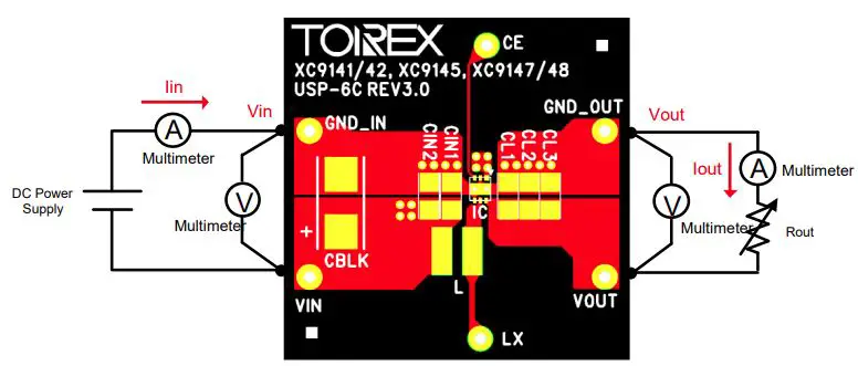
Quick Start Procedure
The following components are required for the quick start procedure:
- DC power supply
- Multimeter (for measuring input voltage, output voltage, output current, and output resistance)
Connect the DC power supply to the input voltage (Vin) and use the multimeter to measure the input voltage (Iin), output voltage (Vout), output current (Iout), and output resistance (Rout). Refer to the schematic diagram below for component placement.
Schematic

Test Results
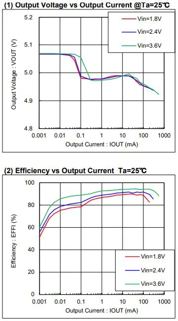
The following test results were obtained at Ta=25:
- Output Voltage vs Output Current
- Efficiency vs Output Current
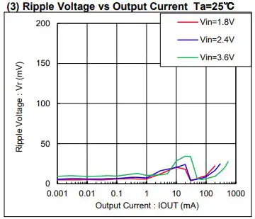
- Ripple Voltage vs Output Current
Refer to Graphs 1-3 in the manual for more information.
CAUTION
ENGINEERING EVALUATION PURPOSES ONLY
This evaluation board is made for the purpose of the product evaluation. It is strictly prohibited to use this evaluation board for any other purpose.
Torex Semiconductor does not guarantee that all samples will perform in exactly the same way and we recommend that you always consult our product data sheets for the minimum and maximum specifications.
It is also important that you evaluate all our products carefully before mass
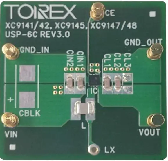
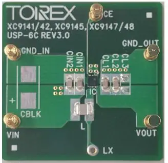
Evaluation Board Picture
Evaluation Board SPEC
| CONDITON. | MIN. | TYP. | MAX. | UNIT | ||
| Vin | Input Voltage Range | – | 0.65 | – | 5.5 | V |
| Operation Start Voltage | – | – | – | 1.6 | V | |
| Vout | Setting Output Voltage | – | – | 5.0 | – | V |
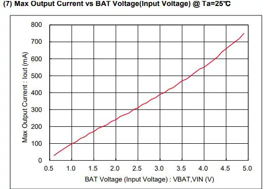
| Iout | Output Current | – | Refer to Graph 7 | mA | ||
| fosc | Switching frequency | – | – | 1.2 | – | MHz |
XC9145 Series Features
- Input Voltage Range ・・・・・・・・・・・・・・・・・・0.65V ~ 5.5V
- Operation Start Voltage ・・・・・・・・・・・・・・・・・・1.6V
- Output Voltage Range ・・・・・・・・・・・・・・・・・・3.0V ~ 5.5V (step 0.1V)
- Switching frequency ・・・・・・・・・・・・・・・・・・1.2MHz
- Ultra Low Power Solution
Quick Start Procedure
Schematic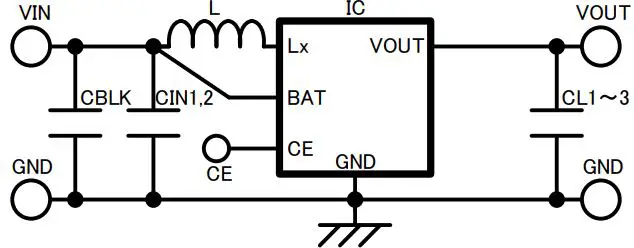
BOM
Required Circuit Component
| Item | Value | Description | Size [mm] | Part Number | Manufacture |
| IC | – | Step-up DC/DC converter | USP-6C | XC9145B50CER-G | TOREX |
| L | 4.7uF | Inductor, Isat=2.1A | 2520 | DFE252012F-4R7M | Murata |
| CIN1 | 10uF | Ceramic cap., 16V/10uF | 1608 | GRM188R61C106MA73 | Murata |
| CIN2 | 10uF | Ceramic cap., 16V/10uF | 1608 | GRM188R61C106MA73 | Murata |
| CL1 | 10uF | Ceramic cap., 16V/10uF | 1608 | GRM188R61C106MA73 | Murata |
| CL2 | 10uF | Ceramic cap., 16V/10uF | 1608 | GRM188R61C106MA73 | Murata |
| CL3 | – | – | – | – | – |
Additional Demo Board Circuit Components
| Item | Value | Description | Size [mm] | Part Number | Manufacture |
| CBLK | – | – | – | – | – |
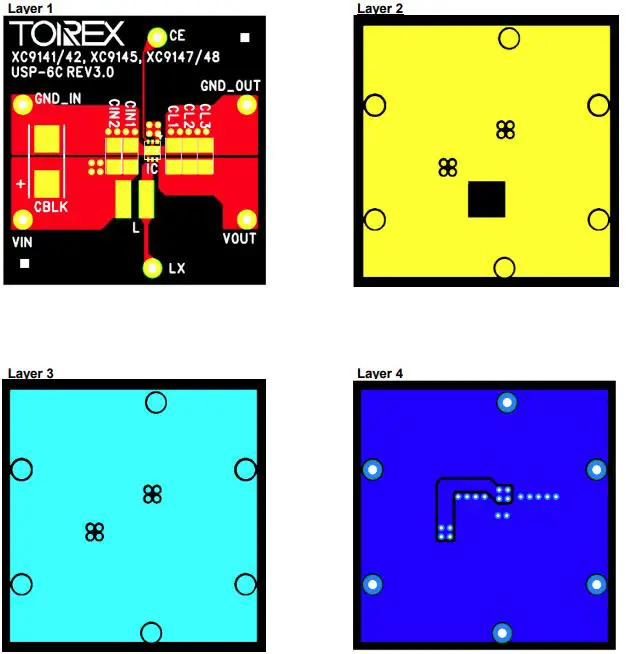
PCB Layout
Test Result
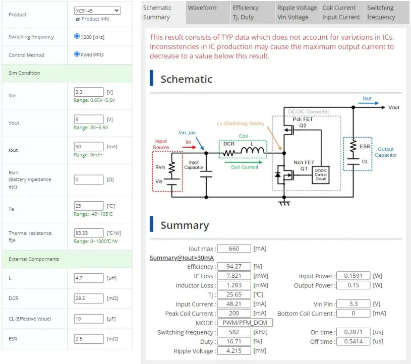
【Appendix】 How to calculate DC/DC Converter or DC/DC Controller.
It can be calculated by the following “WEB DC/DC Simulation”.
【Appendix】 How to reduce the spike noise caused by measurement (Probing method with oscilloscope
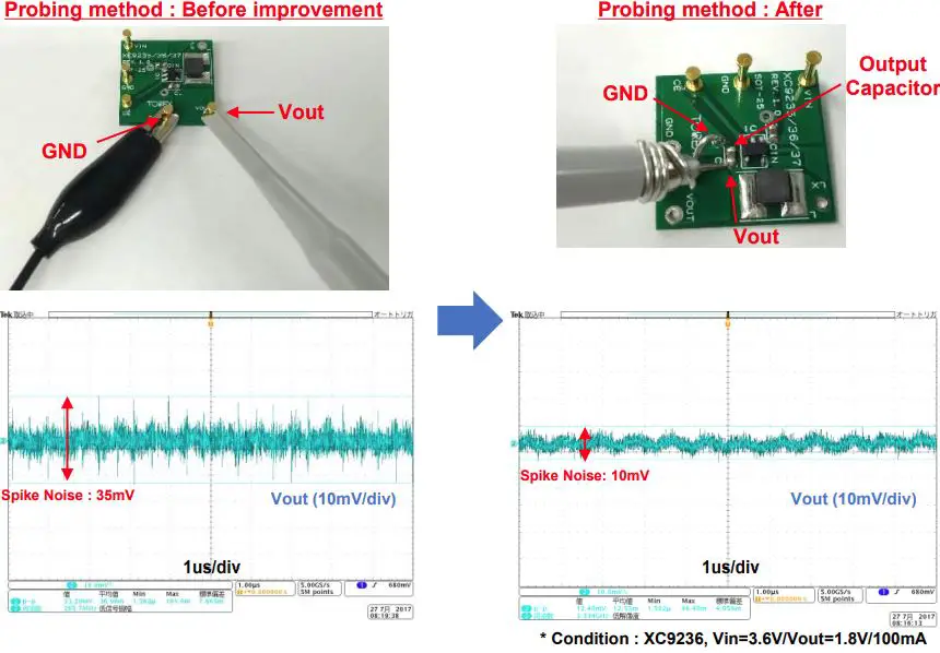
https://www.torexsemi.com/technical-support/tips/reduction-spike-noise/
References
 電源ICのトレックス・セミコンダクター(TOREX)
-
DC/DCシミュレーション | トレックス・セミコンダクター株式会社 | 電源ICのトレックス・セミコンダクター
-
技術情報 | トレックス・セミコンダクター株式会社 | 電源ICのトレックス・セミコンダクター
 DC/DC模拟器 | 特瑞仕半导体株式会社 | 电源IC专业厂家 特瑞仕半导体
 DC/DC Simulation | TOREX SEMICONDUCTOR LTD. | Your analog power IC and the best power management
-
Technical Information | TOREX SEMICONDUCTOR LTD. | Your analog power IC and the best power management


