
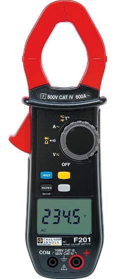
CHAUVIN ARNOUX F201 Clamp Multimeter
F402 Clamp Multimeter
The F402 clamp multimeter is a versatile device designed for measuring AC/DC voltage, current, resistance, continuity, diode test, frequency, and starting current or over-current. It is capable of measuring up to 1000V CAT IV and 1500V CAT III.
Delivery Condition
The F402 clamp multimeter is delivered with the following items:
- F402 clamp multimeter
- Test leads
- Battery (installed)
- User manual
Keys
The F402 clamp multimeter has several keys:
 key: freezes the displayed value
- REL key: used for relative measurements
 key: displays the maximum or minimum value measured
 key: used for frequency measurements
Usage Instructions
Before using the F402 clamp multimeter, it is important to read the user manual and observe the precautions for its use.
To measure voltage or current, follow these steps:
- Make sure the device is turned off and the test leads are connected properly
- Turn on the device and select the appropriate measurement category (IV, III, or II)
- Select AC or DC measurement mode using the dial
- Place the clamp around the wire or conductor to be measured
- Read the measured value on the display
To measure resistance, continuity, diode, or frequency, follow the instructions provided in the user manual.
Always use caution when working with electrical devices and follow proper safety procedures to avoid injury or damage to the device.
You have just acquired an F402 clamp multimeter and we thank you. For best results from your device:
- read this user manual attentively,
- observe the precautions for its use.
- WARNING, risk of DANGER ! The operator should refer to this user’s manual whenever this danger symbol appears.
- Application or withdrawal authorized on bare conductors carrying dangerous voltages. Type A current sensor as per IEC/EN 61010-2-032 or BS EN 61010-2-032.
Battery. - Equipment protected throughout by double or reinforced insulation.
- Earth.
- The CE marking indicates compliance with the European Low Voltage Directive (2014/35/EU), Electromagnetic Compatibility Directive (2014/30/EU), and Restriction of Hazardous Substances Directive (RoHS, 2011/65/EU and 2015/863/EU).
- The UKCA marking certifies that the product is compliant with the requirements that apply in the United Kingdom, in particular as regards Low-Voltage Safety, Electromagnetic
- Compatibility, and the Restriction of Hazardous Substances.
- AC – Alternating current.
- AC and DC – Alternating and direct current.
- The rubbish bin with a line through it indicates that, in the European Union, the product must undergo selective disposal in compliance with Directive WEEE 2012/19/EU. This equipment must not be treated as household waste.
Definitions of the measurement categories
- Measurement category IV corresponds to measurements taken at the source of low-voltage installations.
Example: power feeders, meters and protection devices. - Measurement category III corresponds to measurements on building installations.
Example: distribution panel, circuit-breakers, machines or fixed industrial devices. - Measurement category II corresponds to measurements taken on circuits directly connected to low-voltage installations. Example: power supply to domestic electrical appliances and portable tools.
PRECAUTIONS FOR USE
This device complies with safety standards IEC/EN 61010-1 or BS EN 61010-1 and IEC/EN 61010-2-032 or BS EN 61010-2-032 for voltages of 1 000 V in category IV and 1 500 V in category III, less than 2 000 m, indoors, with a degree of pollution not exceeding 2.
These safety instructions are intended to ensure the safety of persons and proper operation of the device. If the tester is used other than as specified in this data sheet, the protection provided by the device may be impaired.
- The operator and/or the responsible authority must carefully read and clearly understand the various precautions to be taken in use.
- If you use this instrument other than as specified, the protection it provides may be compromised, thereby endangering you.
- Do not use the instrument in an explosive atmosphere or in the presence of flammable gases or fumes.
- Do not use the instrument on networks of which the voltage or category exceeds those mentioned.
- Do not exceed the rated maximum voltages and currents between terminals or with respect to earth.
- Do not use the instrument if it appears to be damaged, incomplete, or not properly closed.
- Before each use, check the condition of the insulation on the leads, housing, and accessories. Any element of which the insulation is deteriorated (even partially) must be set aside for repair or scrapped.
- Use leads and accessories rated for voltages and categories at least equal to those of the instrument. If not, an accessory of a lower category lowers the category of the combined Clamp + accessory to that of the accessory.
- Observe the environmental conditions of use.
- Do not modify the instrument and do not replace components with “equivalents”. Repairs and adjustments must be done by approved qualified personnel.
- Replace the batteries as soon as the symbol
 appears on the display unit. Disconnect all cords before opening the battery compartment cover.
 - Use personal protective equipment when conditions require.
- Keep your hands away from the unused terminals of the instrument.
- When handling the test probes, crocodile clips, and clamp ammeters, keep your fingers behind the physical guard.
- As a safety measure, and to avoid repeated overloads on the inputs of the device, we recommend performing configuration operations only when the device is disconnected from all dangerous voltages.
DELIVERY CONDITION
The F402 clamp multimeter is delivered in its packaging box with:
- 2 banana-banana leads, one red and one black
- 2 test probes, one red and one black
- 1 K thermocouple with banana terminations
- 4 1.5 V batteries
- 1 carrying bag
- 1 multilingual getting started guide.
For accessories and spares, visit our web site: www.chauvin-arnoux.com
PRESENTATION
The F402 is a professional electrical measuring instrument that combines the following functions:
- Current measurement,
- Measurement of inrush current / over current (True-Inrush),
- Voltage measurement,
- Frequency measurement,
- Continuity test with buzzer,
- Resistance measurement,
- Diode test,
- Temperature measurement,
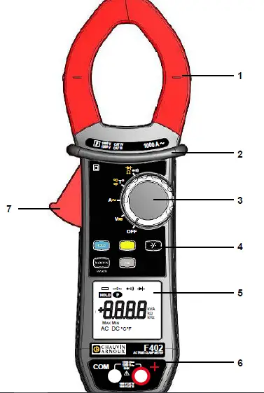
Figure 1: the F402 clamp multimeter
| Item | Designation | See § |
| 1 | Jaws with centering marks (see connection principles) | 4.5 to 4.12 |
| 2 | Physical guard | – |
| 3 | Switch | 2.1 |
| 4 | Function keys | 3 |
| 5 | Display unit | 2.3 |
| 6 | Terminals | 2.4 |
| 7 | Trigger | – |
THE SWITCH
The switch has five positions. To access the ![]() ,
,![]() ,
, ![]()
 functions, set the switch to the desired function. Each setting is confirmed by an audible signal. The functions are described in the table below:
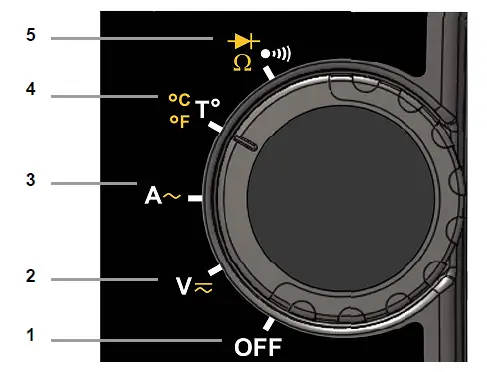
| Item | Function | See § | |||
| 1 | OFF mode – Switches the clamp multimeter off | 4.3 | |||
| 2 | AC, DC voltage measurement (V) | 4.5 | |||
| 3 | AC, current measurement (A) | 4.9 | |||
| 4 | Temperature measurement (°C/°F) | 4.12 | |||
| 5 | Continuity test Resistance measurement Ω Diode test | 4.6 | |||
THE KEYS OF THE KEYPAD
Here are the five keys of the keypad:

Figure 3: the keys of the keypad
| Item | Function | See § |
| 1 | Storage of values, disabling of display Compensation of the resistance of the leads in the continuity and ohmmeter function | 3.1 |
| 2 | Selection of the type of measurement (AC, DC) | 3.2 |
| 3 | Activation or de-activation of the backlighting of the diplay unit | 3.3 |
| 4 | Activation or de-activation of the | 3.4 |
| 5 | Measurements of frequency ( | 3.5 |
THE DISPLAY UNIT
Here is the display unit of the clamp multimeter:
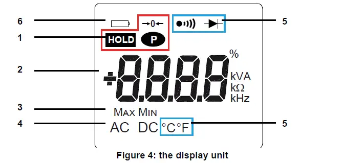
| Item | Function | See § |
| 1 | Display of the modes selected (keys) | 3 |
| 2 | Display of the measurement value and unit | 4.5 to 4.12 |
| 3 | Display of the | 3.4 |
| 4 | Type of measurement (AC or DC) | 3.2 |
| 5 | Display of the selected modes (switch) | 4.5 |
| 6 | Spent battery indication | 6.2 |
THE SYMBOLS OF THE DISPLAY UNIT
| Symbol | Designation | ||
| AC | Alternating current or voltage | ||
| DC | Direct current or voltage | ||
| Storage of the values and hold of the display | |||
| Max | Maximum RMS value | ||
| Min | Minimum RMS value | ||
| V | Volt | ||
| Hertz | |||
| A | Ampere | ||
| Ω | Ohm | ||
| m | Milli-prefix | ||
| k | Kilo-prefix | ||
| → o ← | Compensation of the resistance of the leads | ||
 | Continuity test | ||
 | Diode test | ||
 | Permanent display (automatic switching off de-activated) | ||
| Spent battery indicator | |||
MEASUREMENT CAPACITY EXCEEDED ( O.L)
The O.L (Over Load) symbol is displayed when the display capacity is exceeded.
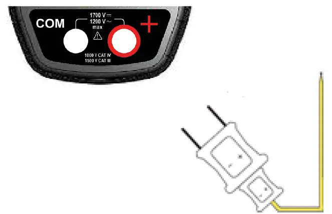
THE TERMINALS
The terminals are used as follows:
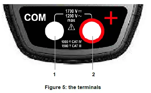
| Item | Function |
| 1 | Cold terminal (COM) |
| 2 | Hot terminal (+) |
THE KEYS
The keys of the keypad respond differently to short, long, and sustained presses.
The ![]() and
and ![]() keys provide new functions and allow the detection and acquisition of parameters complementary to the usual elementary measurements.
keys provide new functions and allow the detection and acquisition of parameters complementary to the usual elementary measurements.
Each of these keys can be used independently of the others or in perfect complementarity with them: this makes navigation simple and intuitive for looking up all measurement results.
It is possible, for example, to look up in turn the MAX, MIN, etc. values of the RMS voltage only, then display relative values in parallel.
In this section, the![]() icon represents the possible positions of the switch for which the key concerned has some action.
icon represents the possible positions of the switch for which the key concerned has some action.
![]() HOLD KEY
HOLD KEY
This key is used to:
- store and look up the last values acquired specific to each function (V, A, Ω, T°) according to the specific modes previously activated (, ); the present display is then maintained while the detection and acquisition of new values continues;
- perform automatic compensation of the resistance of the leads (see also § 4.6.1);
| Successive presses on HOLD |
| … serve |
| short |
| to stored the results of the present measurements, to hold the display of the last value displayed, to return to normal display mode (the value of each new measurement is displayed) |
| sustained |  | to perform automatic compensation of the resistance of the leads (see § 4.6.1) |
See also § 3.4.2 and § 3.5.2 for the action HOLD key with the action of the ![]() key and with the action of the
key and with the action of the ![]() key.
key.
![]() KEY (SECOND FUNCTION)
KEY (SECOND FUNCTION)
This key is used to select the type of measurement (AC, DC) and the second functions marked in yellow next to the relevant positions of the switch.
It can also be used, in the configuration mode, to modify the default value (see § 4.4).
Remark: the key is invalid in the ![]() and
and ![]() modes.
modes.
| Successive presses on | … serve | |
| to select AC or DC. Depending on your choice, the screen displays AC or DC. | |
| to cycle through the Ω and diode test modes and to return to the continuity test . | |
| to select °C or °F as the unit |
KEY
This key is used to backligth the display unit.
| Successive presses on | … serve | |
| to activate or de-activate the backlighting of the screen |
Remark: the backlighting is switched off automatically at the end of 2 minutes.
![]() KEY
KEY
IN THE NORMAL MODE
This key activates detection of the MAX and MIN values of the measurements made. Max and Min are the extreme mean values in DC and the extreme RMS values in AC.
Remark: in this mode, the “automatic switching off” function of the device is automatically de-activated. The ![]() symbol is displayed on the screen.
symbol is displayed on the screen.
| Successive presses on | … serve | |
| short |
|
Remark: the MAX, MIN symbols are both displayed, but only the symbol of the quantity selected blinks. Example: If MIN ha been selected, MIN blinks and MAX is lit steadily. |
| long (> 2 sec) |
| to exit from the Remark: if the HOLD function is activated, it is not possible to exit from the MAX/ MIN mode. The |
THE ![]() MODE + ACTIVATION OF THE HOLD MODE
MODE + ACTIVATION OF THE HOLD MODE
| Successive presses on | … serve | |
| short |
| to display successively the
|
Note: the HOLD![]() function does not interrupt the acquisition of new MAX, MIN values.
function does not interrupt the acquisition of new MAX, MIN values.
ACCESS TO THE TRUE-INRUSH MODE ( ![]() SET TO A )
SET TO A )
This key allows measurement of the True-Inrush current (starting current, or over-current in steady-state operation) for AC or DC current only.
| Successive presses on | … serves | |
| long (> 2 sec) | 
|
|
| short (< 2 sec) Note: a short press is functional only if an True-Inrush value has been detected. | |
Remark: the A symbol is displayed steadily this sequence. |
![]() KEY
KEY
This key is used to display the frequency measurements of a signal. Remark: this button is not functional in DC.
THE Hz FUNCTION IN THE NORMAL MODEL
| Successive presses on | … serves | |
| short |  |
|
THE ![]() FUNCTION + ACTIVATION OF THE HOLD MODE
FUNCTION + ACTIVATION OF THE HOLD MODE
| Successive presses on | … serves | |
| short | |
|
USE
COMMISSIONING
Insert the batteries supplied with the device as follows:
- Using a screwdriver, unscrew the screw of the battery compartment cover (item 1) on the back of the housing and open it ;
- Place the 4 batteries in the compartment (item 2), taking care to get the polarities right ;
- Close the battery compartment cover and screw it to the housing.
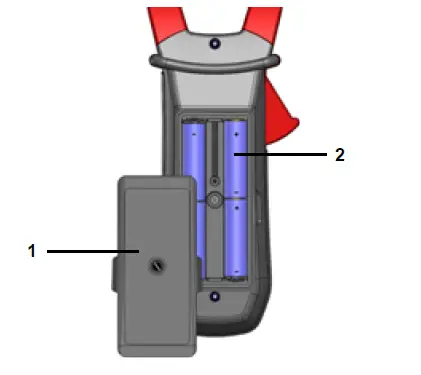
Figure 6: the battery compartment cover
STARTING UP THE CLAMP MULTIMETER
The switch is set to OFF. Turn the switch to the function of your choice. The whole display lights (all symbols) for a few seconds (see § 2.3), then the screen of the function chosen is displayed. The clamp multimeter is then ready to make measurements.
SWITCHING THE CLAMP MULTIMETER
The clamp multimeter can be switched off either manually, by setting the switch to OFF, or automatically, after ten minutes with no action on the switch and/or the keys. Thirty (30) seconds before the device is switched off, an audible signal sounds intermittently. To re-activate the device, press any key or turn the switch.
CONFIGURATION
As a safety measure, and to avoid repeated overloads on the inputs of the device, we recommend performing configuration operations only when the device is disconnected from all dangerous voltages.
PROGRAMMING OF THE MAXIMUM RESISTANCE ALLOWED FOR A CONTINUITY
To program the maximum resistance allowed for a continuity:
- From the OFF position, hold the
 key down while turning the switch to
 , until the “full screen” display ends and a beep is emitted, to enter the configuration mode. The display unit indicates the value below which the buzzer is activated and the symbol is displayed
 .
.
The value stored by default is 40 Ω. The possible values lie between 1 Ω and 999 Ω. - To change the threshold, press the key. The right-hand digit flashes: each press on the to the next digit, apply a long press (> 2 s) to the key.
To exit from the programming mode, turn the switch to another setting. The detection threshold chosen is stored (emission of a double beep).
DE-ACTIVATION OF AUTOMATIC SWITCHING OFF (AUTO POWER OFF)
To de-activate automatic switching off:
- In the OFF position, hold the HOLD key down while turning the switch to
 , until the “full screen” display ends and a beep is emitted, to enter the configuration mode. The
  symbol is displayed.
 - When the HOLD key is released, the device is in the voltmeter function in the normal mode.
- The return to Auto Power OFF takes place when the clamp is switched back on.
PROGRAMMING OF THE CURRENT THRESHOLD FOR THE TRUE INRUSH MEASUREMENT
To program the triggering current threshold of the True INRUSH measurement:
- In the OFF position, hold the key down while turning the switch to
 , until the “full screen” display ends and a beep is emitted, to enter the configuration mode. The display unit indicates the percentage overshoot to apply to the measured current to determine the measurement triggering threshold.
The value stored by default is 10 %, representing 110 % of the established current measured. The possible values are 5 %, 10 %, 20 %, 50 %, 70 %, 100 %, 150 %, and 200 %. - To change the threshold, press the key. The value flashes: each press on the key displays the next value. To record the chosen threshold, apply a long press (> 2 s) on the key. A confirmation beep is emitted.
To exit from the programming mode, turn the switch to another setting. The chosen threshold is stored (emission of a double beep).
Note: The starting current measurement triggering threshold is fixed at 1 % of the least sensitive range. This threshold is not adjustable.
CHANGE OF TEMPERATURE MEASUREMENT UNIT
To program the measurement unit, °C or °F:
- In the OFF position, hold the key down while turning the switch to
 , until the “full screen” display ends and a beep is emitted, to enter the configuration mode. The display unit indicates the existing unit (°C or °F). The default unit is °C.
 - Pressing the key toggles between °C and °F.
When the desired unit is displayed, turn the switch to another setting. The unit chosen is stoored (emission of a double beep).
DEFAULT CONFIGURATION
To reset the clamp to its default parameters (factory configuration):
In the OFF position, hold the key ![]() down while turning the switch to
down while turning the switch to ![]() , until the “full screen” display ends and a beep is emitted, to enter the configuration mode. The “rSt” symbol is displayed.
, until the “full screen” display ends and a beep is emitted, to enter the configuration mode. The “rSt” symbol is displayed.
After 2 s, the clamp emits a double beep, then all of the symbols of the screen are displayed until the![]() default parameters are then restored:
default parameters are then restored:
- Continuity detection threshold = 40 Ω
- True Inrush triggering threshold = 10 %
- Temperature measurement unit = °C
- Adapter function scale factor = 1
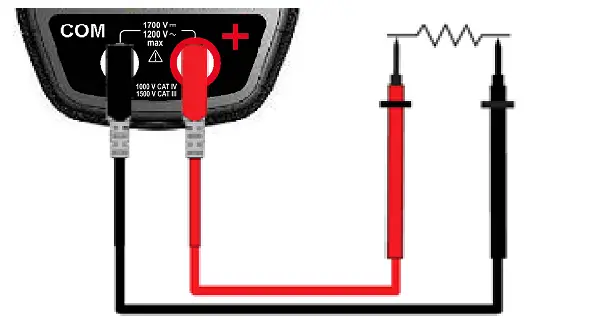
VOLTAGE MEASUREMENT (V)
To measure a voltage, proceed as follows:
- Set the switch to ,
- Connect the black lead to the COM terminal and the red lead to “+”,
- Place the test probes or the crocodile clips on the terminals of the circuit to be measured. The device selects AC or DC automatically according to which measured value is larger. The AC or DC symbol lights in blinking mode.
To select AC or DC manually, press the yellow key to reach the desired choice. The symbol corresponding to the choice made then lights in fixed mode.
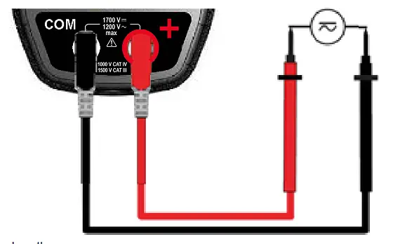
The measured value is displayed on the screen.
CONTINUITY TEST
Warning: Before performing the test, make sure that the circuit is off an any capacitors have been discharged.
- Set the switch to , the symbol is displayed.
- Connect the black lead to the “COM” terminal and the red lead to “+”.
- Place the test probes or the crocodile clips on the terminals of the circuit or component to be tested.
An audible signal is emitted if there is continuity, and the measured value is displayed on the screen.
AUTOMATIC COMPENSATION OF THE RESISTANCE OF THE LEADS
Warning: before the compensation is executed, the ![]() and
and ![]() modes must be de-activated.
modes must be de-activated.
To perform automatic compensation of the resistance of the leads, proceed as follows:
- Short-circuit the leads connected to the device.
- Hold the key down until the display unit indicates the lowest value. The device measures the resistance of the leads.
- Release the key. The correction and the →0← symbol are displayed. The value displayed is stored.
Remark: The correction value is stored only if it is ≤ 2 Ω. Above 2 Ω, the value displayed blinks and is not stored.
RESISTANCE MEASUREMENT Ω
Warning: Before making a resistance measurement, make sure that the circuit is cold and any capacitors have been discharged.
- Set the switch to and press the key.
The Ω symbol is displayed. - Connect the black lead to the “COM” terminal and the red lead to “+”.
- Place the test probes or the crocodile clips on the terminals of the circuit or component to be measured.
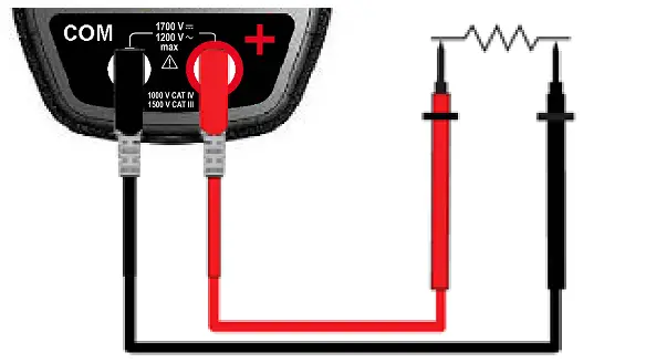
The measured value is displayed on the screen.
Remark: to measure low resistance values, first carry out the compensation of the resistance of the leads (see § 4.6.1)
DIODE TEST
Warning: Before performing the diode test, make sure that the circuit is cold and any capacitors have been discharged.
- Set the switch to and press the key twice. The
 symbol is displayed.
 - Connect the black lead to the “COM” terminal and the red lead to “+”.
- Place the test probes or the crocodile clips on the terminals of the component to be tested.

The measured value is displayed on the screen.
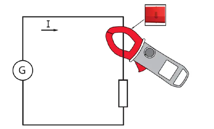
CURRENT MEASUREMENT (A)
The jaws are opened by pressing the trigger on the body of the device. The arrow on the jaws of the clamp (see the diagram below) must point in the presumed direction of flow of the current, from the generator to the load. Make sure that the jaws have closed correctly.
Remark: the measurement results are optimal when the conductor is centered in the jaws (aligned with the centering marks).
AC MEASUREMENT
For an AC current measurement, proceed as follows:
- Set the switch to
- Encircle only the conductor concerned with the clamp.
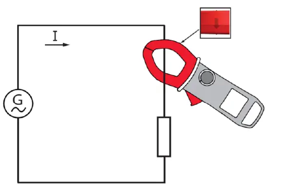
The measured value is displayed on the screen.
STARTING CURRENT OR OVER-CURRENT (TRUE INRUSH) MEASUREMENT
To measure a starting current or over current, proceed as follows:
- Set the switch to , then apply the clamp around the single conductor concerned.
- Effect a long press on the key. The InRh symbol is displayed, then the triggering threshold. The clamp then awaits detection of the True-Inrush current. “——” is displayed and the “A” symbol flashes.
- After detection and acquisition for 100 ms, the RMS value of the True-Inrush current is displayed, along with the PEAK+/PEAK- values subsequently.
- A long press on the key or a change of function leads to exiting from the True-Inrush mode.
Remark: the triggering threshold in A is 20 A if the initial current is zero (starting of installation), it is that set in the configuration (see § 4.4) for an established current (overload in a installation).
FREQUENCY MEASUREMENT (![]() )
)
The frequency measurement is available in V and A for AC quantities. The measurement is based on a count of the passages of the signal through zero (positive-going edges).
FREQUENCY MEASUREMENT IN VOLTAGE
To measure the frequency in voltage, proceed as follows:
- Set the switch to and press the key. The symbol is displayed.
- Select AC by pressing the yellow key until the desired choice is reached.
- Connect the black lead to the “COM” terminal and the red lead to “+”.
- Place the test probes or the crocodile clips on the terminals of the circuit to be measured.
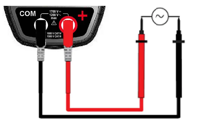
The measured value is displayed on the screen.
FREQUENCY MEASUREMENT IN CURRENT
- Set the switch to and press the key. The “” symbol is displayed.
- Select AC by pressing the yellow key until the desired choice is reached.
- Encircle only the conductor concerned with the clamp.
The measured value is displayed on the screen.
TEMPERATURE MEASUREMENT
MEASUREMENT WITHOUT EXTENAL SENSOR
- Set the switch to .
The temperature displayed (blinking) is the internal temperature of the device, equal to the ambient temperature after a sufficiently
long thermal stabilization time (at least one hour).
MEASUREMENT WITH EXTERNAL SENSOR
The device measures the temperature using a K thermocouple.
- Connect the K thermocouple to the + and COM input terminals of the device.
- Set the switch to .
- Place the K thermocouple on the element or zone to be measured, which must not be at a dangerous voltage
The temperature is displayed on the screen.
To change the unit, °F or °C, press the key![]() .
.
Remarks:
- If the external sensor is defective, the temperature displayed blinks.
- If there are large variations of the environment of the device, the measurement must be preceded by a stabilization time.
CHARACTERISTICS
REFERENCE CONDITIONS
| Quantities of influence | Reference conditions |
| Temperature | 23°C ± 2°C |
| Relative humidity | 45 % to 75 % |
| Supply voltage | 6.0 V ± 0.5 V |
| Frequency range of the applied signal | 45 – 65 Hz |
| Sine wave | pure |
| Peak factor of the applied alternating signal | √ 2 |
| Position of the conductor in the clamp | centred |
| Adjacent conductors | none |
| Alternating magnetic field | none |
| Electric field | none |
CHARACTERISTICS UNDER THE REFERENCE CONDITIONS
The uncertainties are expressed in ± (x % of the reading (R) + y points (pt)).
DC VOLTAGE MEASUREMENT
| Measurement range | 0.00 V to 99.99 V | 100.0 V to 999.9 V | 1 000 V to 1 700 V |
| Specified measurement range | 0 to 1 600 V | ||
| Uncertainties | from 0.00 V to 9.99 V ± (1 % R + 10 pts) from 10.00 V to 99.99 V ± (1 % R + 3 pts) | ± (1 % R + 4 pts) | |
| Resolution | 0.01 V | 0.1 V | 1 V |
| Input impedance | 10 MΩ | ||
AC VOLTAGE MEASUREMENT
| Measurement range | 0.15 V to 99.99 V | 100.0 V to 999.9 V | 1 000 V to 1 200 V RMS 1 700 V peak (1) |
| Specified measurement range (2) | 0 to 1 100 VAC / 1 600 V peak | ||
| Uncertainties | from 0.15 V to 9.99 V ± (1 % R + 10 pts) from 10.00 V to 99.99 V ± (1 % R + 3 pts) | ± (1 % R + 4 pts) | |
| Resolution | 0.01 V | 0.1 V | 1 V |
| Input impedance | 10 MΩ | ||
Note
- The display indicates “OL” above 1 700 V.
Above 1 200 V RMS, a repetitive beep indicates that the voltage being measured is greater than the safety voltage for which the device is guaranteed.
Bandwidth in AC = 3 kHz. - Any value between zero and the min. threshold of the measurement range (0.15 V) is forced to “——” on the display.
AC CURRENT MEASUREMENT
| Measurement range (2) | 0.25 A to 99.99 A | 100.0 A to 999.9 A | 1 000 A (1 500 A peak) (1) |
| Specified measurement range | 0 to 100 % of the measurement range | ||
| Uncertainties | ± (1 % R + 10 pts) | ± (1 % R + 3 pts) | |
| Resolution | 0.01 A | 0.1 A | 1 A |
Note
- The display indicates “OL” above 1 500 A. Bandwidth in AC = 1 kHz.
- Any value between zero and the min. threshold of the measurement range (0.25 A) is forced to “——” on the display.
TRUE-INRUSH MEASUREMENT
| Measurement range | 10 A to 1 000 AAC | 10 A to 1 500 ADC |
| Specified measurement range | 0 to 100 % of the measurement range | |
| Uncertainties | ± (5 % R + 5 pts) | |
| Resolution | 1 A | |
Specific characteristics in PEAK mode in True-Inrush (from 10 Hz to 1 kHz in AC):
- Uncertainties: add ± (1.5 % R + 0.5 A) to the values in the tables above.
- PEAK capture time: 1 ms min. to 1.5 ms max.
CONTINUITY MEASUREMENT
| Measurement range | 0.0 Ω to 999.9 Ω |
| Open-circuit voltage | ≤ 3.6 V |
| Measurement current | 550 µA |
| Uncertainties | ± (1 % R + 5 pts) |
| Buzzer triggering threshold | Adjustable from 1 Ω to 999 Ω (40 Ω is the default) |
RESISTANCE MEASUREMENT
| Measurement range (1) | 0.0 Ω to 99.9 Ω | 100.0 Ω to 999.9 Ω | 1 000 Ω to 9999 Ω | 10.00 kΩ to 99.99 kΩ |
| Specified measurement range | 1 to 100 % of the measurement range | 0 to 100 % of the measurement range | ||
| Uncertainties | ± (1% R + 10 pts) | ± (1 % R + 5 pts) | ||
| Resolution | 0.1 Ω | 1 Ω | 10 Ω | |
| Open-circuit voltage | ≤ 3.6 V | |||
| Measurement current | 550 µA | 100 µA | 10 µA | |
Note
- Above the maximum display value, the display unit indicates “OL”.
The “-” and “+” signs are not managed.
Specific characteristics in MAX-MIN mode:
- Uncertainties: add 1 % R to the values of the table above.
- Capture time of the extrema: approximately 100 ms.
DIODE TEST
| Measurement range | 0.000 V to 3.199 VDC |
| Specified measurement range | 1 to 100 % of the measurement range |
| Uncertainties | ± (1 % R + 10 pts) |
| Resolution | 0.001 V |
| Measurement current | 0.55 mA |
| Indication: junction reversed or open-circuit | Display of “OL” when the measured voltage > 3,199 V |
Note: The “-” sign is disabled for the diode test function.
FREQUENCY MEASUREMENT
Characteristics in voltage
| Measurement range (1) | 5.0 Hz to 999.9 Hz | 1 000 Hz to 9 999 Hz | 10.00 kHz to 19.99 kHz |
| Specified measurement range | 1 to 100 % of the measurement range | 0 to 100 % of the measurement range | |
| Uncertainties | ± (0.4 % R + 1 pt) | ||
| Resolution | 0.1 Hz | 1 Hz | 10 Hz |
Characteristics in current
| Measurement range (1) | 5.0 Hz to 999.9 Hz |
| Specified measurement range | 1 to 100 % of the measurement range |
| Uncertainties | ± (0.4 % R + 1 pt) |
| Resolution | 0.1 Hz |
Note
- If the level of the signal is too low (U < 3 V or I < 3 A) or if the frequency is less than 5 Hz, the device cannot determine
the frequency and displays dashes “——“.
Specific characteristics in ![]() mode (from 10 Hz to 1 kHz in voltage and from 10 Hz to 1 kHz in current):
mode (from 10 Hz to 1 kHz in voltage and from 10 Hz to 1 kHz in current):
- Uncertainties: add 1 % R to the values of the table above.
- Capture time of the extrema: approximately 100ms.
TEMPERATURE MEASUREMENT
| Function | External temperature | |
| Type of sensor | K thermocouple | |
| Measurement range | -60.0°C to +999.9°C -76.0°F to +1 831.8°F | +1 000°C to +1 200°C +1 832°F to +2 192°F |
| Etendue de mesure spécifiée | 1 to 100 % of the measurement range | 0 to 100 % of the measurement range |
| Uncertainties (1) | 1% R ±3°C 1% R ±5.4°F | 1% R ±3°C 1% R ±5.4°F |
| Resolution | 0.1°C 0.1°F | 1°C 1°F |
Note
- The stated external temperature measurement accuracy does not take the accuracy of the K thermocouple into account.
- Use of the thermal time constant (0.7 min/°C):
If there is a sudden variation of the temperature of the clamp, by 10°C for example, the clamp will be at 99 % (cnst=5) of the final temperature after 0.7 min/°Cx5-35 min (to which must be added the constant of the external sensor).
Specific characteristics in ![]() mode:
mode:
- Uncertainties: add 1 % R to the values of the table above.
- Capture time of the extrema: approximately 100 ms.
ENVIRONMENTAL CONDITIONS
| Environmental conditions | in use | in storage |
| Temperature | – 20°C to + 55°C | – 40°C to + 70°C |
| Relative humidity (RH) | ≤ 90 % to 55°C | ≤ 90 % up to 70°C |
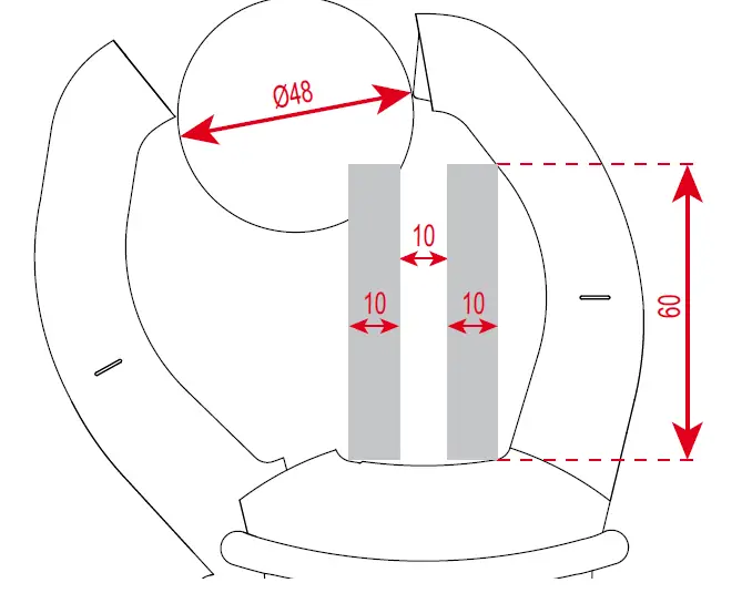
CHARACTERISTICS OF CONSTRUCTION
| Housing | Rigid polycarbonate shell with moulded elastomer covering |
| Jaws | Polycarbonate Opening: 48 mm Clamping diameter: 48 mm |
| Screen | LCD display unit Blue backlighting Dimension: 41 x 48 mm |
| Dimension | H-272 x W-92 x D-41 mm |
| Weight | 600 g (with the batteries) |
POWER SUPPLY
| Batteries | 4 x 1.5 V LR6 |
| Mean life | > 350 hours (without backlighting) |
| Duration of operation before automatic switching off | After 10 minutes without action on the switch and/or keys |
COMPLIANCE WITH INTERNATIONAL STANDARDS
| Electric safety | Compliant with standards IEC/EN 61010-1 or BS EN 61010-1, IEC/EN 61010-2-032 or BS EN 61010-2-032: 1 000 V CAT IV and 1 500 V CAT III |
| Electromagnetic compatibility | Compliant with standard IEC/EN 61326-1 or BS EN 61326-1 Classification: residential environment |
| Mechanical strength | Free fall: 2 m (in accordance with standard IEC 68-2-32) |
| Level of protection of the housing | Housing: IP 54 (per standard IEC 60529) Jaws: IP 40 |
VARIATIONS IN THE DOMAIN OF USE
| Quantity of influence | Range influence | Quantity influenced | Influence | ||||
| Typical | MAX | ||||||
| Temperature | – 20 … + 55°C | VAC VDC A* Ω
T°C | – 0.1 % R / 10°C 1 % R / 10°C* – (0.2 % R +1°C) / 10°C | 0.1 % R / 10°C 0.5 % R / 10°C + 2 pts 1.5 % R / 10°C + 2 pts* 0.1 % R / 10°C + 2 pts (0.3 % R + 2°C) / 10°C | |||
| Humidity | 10 % … 90 %HR | Ω | V A | ≤ 1 pt – 0.2 % R | 0.1 % R + 1 pt 0.1 % R + 2 pts 0.3 % R + 2 pts | ||
| Frequency | 10 Hz … 1 kHz 1 kHz … 3 kHz 10 Hz … 400 Hz 400 Hz … 2 kHz | V A | 1 % R + 1 pt 8 % R + 1 pt 1 % R + 1 pt 4 % R + 1 pt | 1 % R + 1 pt 9 % R + 1 pt 1 % R + 1 pt 5 % R + 1 pt | |||
| Position of the conductor in the jaws (f ≤ 400 Hz) | Any position on the internal perimeter of the jaws | A | 1,5 % R | 3 % R + 1 pt | |||
| Adjacent conductor carrying a current of 150 A DC or RMS | Conductor touching the external perimeter of the jaws | A | 42 dB | 35 dB | |||
| Conductor enclosed by the clamp | 0-500 ADC or RMS | V | < 1 pt | 1 pt | |||
| Application of a voltage of the clamp | 0-1 600 VDC or RMS | A | < 1 pt | 1 pt | |||
| Peak factor | 1.4 to 3.5 limited to 1 500 A peak 1 400 V peak | A (AC) V (AC) | 1 % R 1 % R | 3 % R + 1 pt 3 % R + 1 pt | |||
Note * in temperature: Influence specified until 1 000 ADC
MAINTENANCE
The instrument has no parts that can be replaced by personnel who are not trained and approved. Any non-approved repair or other work, or replacement of a part by an “equivalent”, may severely compromise safety.
CLEANING
- Disconnect everything connected to the device and set the switch to OFF.
- Use a soft cloth moistened with soapy water. Rinse with a damp cloth and dry quickly using a dry cloth or forced air.
- Dry perfectly before putting back into use.
REPLACEMENT OF THE BATTERIES
The symbol ![]() indicates that the batteries are spent. When this symbol appears on the display unit, the batteries must be replaced. The measurements and specifications are no longer guaranteed. To replace the batteries, proceed as follows:
indicates that the batteries are spent. When this symbol appears on the display unit, the batteries must be replaced. The measurements and specifications are no longer guaranteed. To replace the batteries, proceed as follows:
- Disconnect the measurement leads from the input terminals,
- Set the switch to OFF,
- Use a screwdriver to unscrew the screw securing the battery compartment cover to the back of the housing and open the cover (see § 4.1),
- Replace all of the batteries (see § 4.1),
- Close the cover and screw it to the housing.
WARRANTY
Except as otherwise stated, our warranty is valid for 3 years starting from the date on which the equipment was sold. The extract from our General Conditions of Sale is available on our website. www.chauvin-arnoux.com/en/general-terms-of-sale The warranty does not apply in the following cases:
- Inappropriate use of the equipment or use with incompatible equipment;
- Modifications made to the equipment without the explicit permission of the manufacturer’s technical staff;
- Work done on the device by a person not approved by the manufacturer;
- Adaptation to a particular application not anticipated in the definition of the equipment or not indicated in the user’s manual;
- Damage caused by shocks, falls, or floods.
FRANCE
Chauvin Arnoux
12-16 rue Sarah Bernhardt
92600 Asnières-sur-Seine
Tél : +33 1 44 85 44 85
Fax : +33 1 46 27 73 89
[email protected]
www.chauvin-arnoux.com
INTERNATIONAL
Chauvin Arnoux
Tél : +33 1 44 85 44 38
Fax : +33 1 46 27 95 69
Our international contacts
www.chauvin-arnoux.com/contacts


