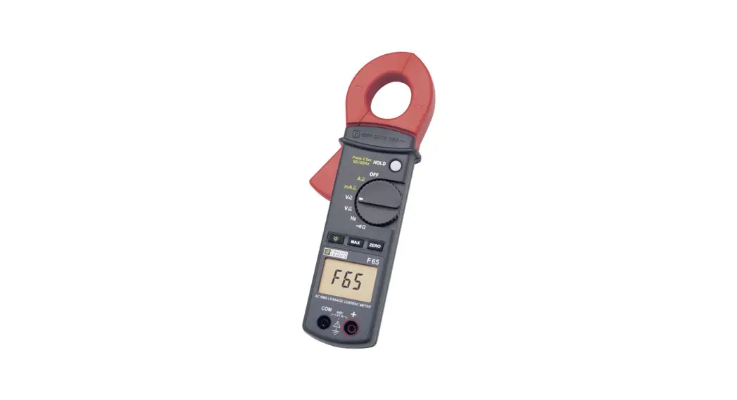
![]() F 65 Clamp meter Digital CAT III 600 V Display
F 65 Clamp meter Digital CAT III 600 V Display
User Manual
Thank you for purchasing a Leakage Clamp-on Meter F65.
For best results from your instrument:![]() read this user manual carefully,
read this user manual carefully,![]() comply with the precautions for use.
comply with the precautions for use.![]() WARNING, DANGER! The operator should refer to this user’s manual whenever this danger symbol appears.
WARNING, DANGER! The operator should refer to this user’s manual whenever this danger symbol appears.![]() Equipment is protected by double insulation.
Equipment is protected by double insulation.![]() Application or withdrawal authorized on bare conductors carrying dangerous voltages, Type A current sensor as per IEC 61010-2-032.
Application or withdrawal authorized on bare conductors carrying dangerous voltages, Type A current sensor as per IEC 61010-2-032.![]() Useful information or tip.
Useful information or tip.![]() The CE marking indicates compliance with the European Low Voltage Directive (2014/35/EU), Electromagnetic Compatibility Directive (2014/30/EU), and Restriction of Hazardous Substances Directive (RoHS, 2011/65/EU, and 2015/863/EU).
The CE marking indicates compliance with the European Low Voltage Directive (2014/35/EU), Electromagnetic Compatibility Directive (2014/30/EU), and Restriction of Hazardous Substances Directive (RoHS, 2011/65/EU, and 2015/863/EU). The rubbish bin with a line through it indicates that, in the European Union, the product must undergo selective disposal in compliance with Directive WEEE 2012/19/EU. This equipment must not be treated as household waste.
GENERAL INSTRUCTIONS
1.1. PRECAUTIONS AND SAFETY MEASURES
1.1.1. BEFORE USE
This clamp-on meter F65 complies with the IEC 61010 safety standard for electronic measuring instruments. For your own safety, and that of the instrument, it is best to follow the instructions given in this manual.
This instrument can be used for measurements on circuits in installation category III, in a pollution level 2 environment, with voltages not exceeding 300 V with respect to the ground.
1.1.2. MEASUREMENT CATEGORIES
(EN 61010-2-032, EN 61010-2-033)
Measurement category IV corresponds to measurements taken at the source of low-voltage installations.
Example: power feeders, meters, and protection devices.
Measurement category III corresponds to measurements on building installations.
Example: distribution panel, circuit-breakers, machines, or fixed industrial devices.
Measurement category II corresponds to measurements taken on circuits directly connected to low-voltage installations.
Example: power supply to domestic electrical appliances and portable tools. 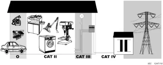
Legend
O: Autrey circuits non connectes directement au RE EAU
CAT II: CATEGORIE DIE MESURE II
CAT III: CATEGORIE DE MESURE III
CAT IV: CATEGORIE DE MESURE IV
For your safety, use only cords that comply with the IEC 61010 standard.
Before each use, check that they are in perfect working condition.
1.1.3. WHILE IN USE
- Never exceed the maximum safe values indicated in the specifications for each type of measurement.
- When the clamp-on meter is connected to the measuring circuits, do not touch any unused terminal.
- Before changing functions, disconnect the measuring cords from the circuit being measured.
- Never perform resistance measurements on a live circuit.
1.1.4. INSTRUCTIONS
Before opening the instrument,
you must disconnect it from the measuring circuits and check that you are not charged with static electricity, which could destroy internal components.
A “qualified person» is someone familiar with the installation, construction, use, and hazards. He/she is authorized to start up and shut down the installation and equipment, in conformity with the safety rules.
1.1.5. UNPACKING – REPACKING
All of the equipment has been checked mechanically and electrically before shipping. Every precaution has been taken to ensure that the instrument reaches you undamaged. It is wise to check it promptly in order to detect any deterioration is found, and state your reservations to the carrier.
Attention! For reshipment, it is best to use the original packaging and state the reasons for returning the equipment as clearly as possible in a note enclosed with it.
DESCRIPTION OF THE INSTRUMENT
2.1. DESCRIPTION OF THE FRONT AND REAR PANELS
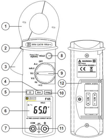
- Jaws
- Protective guard
- Trigger
- MAX function
- Backlighting function
- Display unit
- COM input terminals
- HOLD function / 50-60 Hz filter
- Switch
- Display reset (zero) key
- + Input terminal
- Battery well
2.2. DESCRIPTION OF THE DISPLAY UNIT
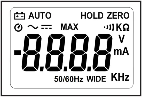
| Batteries low | |
| AUTO | Automatic range |
| MAX | Maximum value display |
| HOLD | Hold mode display |
| ZERO | Relative Measurement displayed |
| Continuity measurement | |
| V | Voltage measurement |
| A | Current measurement |
| …Hz | Frequency measurement |
| 50-60 Hz | Fundamental filter active |
| WIDE | Measurement over the whole passband |
| Automatic shut-off activated | |
| Alternating current / voltage |
GENERAL DESCRIPTION
3.1. PREPARATION FOR USE
3.1.1. POWER SUPPLY
Batteries: AAA or LR03 1.5 V (two)
Battery life: 45 hours (alkaline batteries)
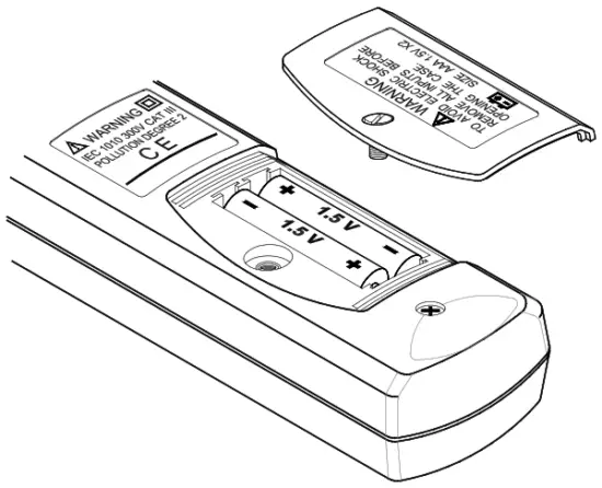
3.1.2. INSTALLATION AND REPLACEMENT OF THE BATTERIES
 is displayed when the voltage delivered by the batteries is below the operating voltage.
- Before replacing the batteries, set the switch to “OFF”, disconnect the measuring cords, and disconnect the clamp from the circuit being measured.
- Loosen the screw and open the cover of the battery compartment with a screwdriver.
- Replace the used batteries with two new 1.5 V LR03 batteries.
- Put the cover back in place and tighten the attachment screw.

3.2. AUTOMATIC RANGES
Range selection is automatic for all functions. The AUTO symbol on the display indicates this operating mode.
3.3. MAXIMUM VALUE (MAX)
In the Ac current and AC&DC voltage measurement modes, the largest value can be measured simply by pressing the «MAX» button.
The MAX symbol then appears on the screen.
The acquisition time is 100 ms.
To deactivate this function, press the «MAX» button again.
3.4. HOLD MODE (HOLD)
The value displayed can be frozen simply by pressing the «HOLD» button. The «HOLD» symbol is then displayed on the screen. To deactivate this function, press the «HOLD» button again.
3.5. RELATIVE VALUE (ZERO)
It is possible to compare two values, in any function except frequency measurement, simply by pressing the «ZERO» button.
When the first value is displayed on the screen, press the ZERO button.
The ZERO symbol then appears on the screen and the display unit indicates the value zero.
Make your second measurement. The display unit then indicates the difference between the second value and the first value.
To deactivate this function, press the «ZERO» button again.
This function can be used to compare two voltage measurements (e.g. to determine a voltage drop) or to correct for the resistance of the cords when making a resistance measurement.
3.6. 50-60 Hz FILTER
It is possible to filter the signal (when making a current measurement), in order to display only the fundamental, by a long press on the «HOLD» button.
The 50/60 Hz symbol, then appears on the screen.
To deactivate this function and return to measuring over the whole passband of the instrument, effect another long press on the «50-60 Hz» button.
The WIDE symbol then appears on the screen.
3.7. AUTOMATIC SHUT-OFF (INSTRUMENT)
The clamp is shut off automatically after 10 minutes if no operation is performed.
The ![]() symbol indicates that the automatic shut-off mode is activated.
symbol indicates that the automatic shut-off mode is activated.
To deactivate automatic shut-off, hold the «ZERO» button down and operate the switch.
The ![]() symbol disappears from the display unit, indicating that the automatic shut-off is deactivated.
symbol disappears from the display unit, indicating that the automatic shut-off is deactivated.
3.8. BACKLIGHTING
Pressing the ![]() key activates the backlighting of the display.
key activates the backlighting of the display.
The backlighting can be switched off manually by pressing the ![]() key; otherwise, it is switched off automatically after 180 seconds.
key; otherwise, it is switched off automatically after 180 seconds.
FUNCTIONAL DESCRIPTION
4.1. ALTERNATING CURRENT MEASUREMENT
(A range)
Set the switch to A~.
Open the clamp by pressing the trigger.
Place the clamp around the conductor to be measured and release the trigger; check that the clamp is properly closed. Read the measurement on the display unit.
Note: As a safety measure, disconnect the measuring cords from the clamp before performing this operation.
The clamp must be placed around a single conductor of a circuit, since otherwise the measurement may be thrown off. The measurement is optimal with the conductor centered in the middle of the jaws
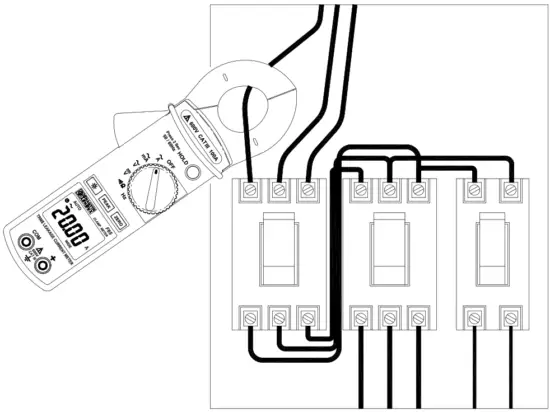
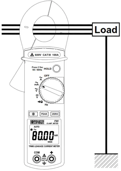
4.2. LEAKAGE CURRENT MEASUREMENT
(mA range)
Note: As a safety measure, disconnect the measuring cords from the clamp before performing this operation.
The measurement is optimal with the conductor centered in the middle of the jaws.
Set the switch to mA~.
Open the clamp by pressing the trigger.
Place the clamp around the active conductors (Phase conductors and Neutral). and release the trigger; check that the clamp is properly closed. Read the measurement on the display unit.
The reading can be filtered to reflect only fundamentals by a long press on the HOLD key, giving an indication of the impact of the harmonics.
4.3. AC AND DC VOLTAGE MEASUREMENT
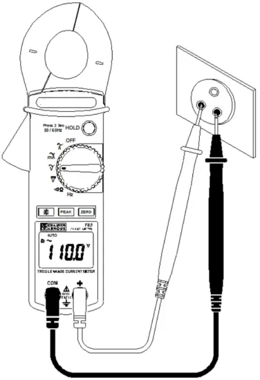
Set the switch to V~ for an AC voltage measurement and to V= for ADC voltage measurement.
Connect the red test cord to the “+” input terminal and the black test cord to the «COM» input terminal.
Then place the probe tips in contact with the points where the AC voltage is to be measured.
Read the result on the display unit.
4.4. RESISTANCE MEASUREMENT
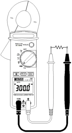
Set the switch to Ω.
Connect the red test cord to the «+» input terminal and the black test cord to the «COM» input terminal.
Place the probe tips in contact with the points to be measured and read the result on the display unit.
Note: Before making a measurement on a circuit, check that it is OFF and that ANY capacitors are discharged.
4.5. AUDIBLE CONTINUITY TEST
Set the switch to ![]() Ω.
Ω.
Connect the red test cord to the «+» terminal and the black test cord to the «COM» input terminal.
Place the probe tips in contact with the circuit to be tested.
If the resistance is less than 35 Ω, the buzzer will sound continuous.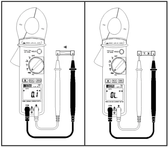
4.6. FREQUENCY MEASUREMENT (HZ)
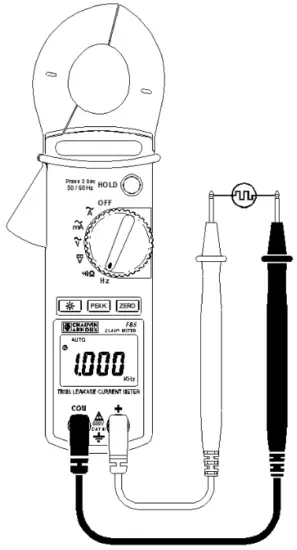 Set the switch to Hz for a frequency measurement in AC voltage mode.
Connect the red test cord to the «+» input terminal and the black test cord to the «COM» input terminal.
Then place the probe tips in contact with the points where the AC voltage is to be measured.
Read the result on the display unit.
Disconnect the probe tip cords from the clamp-on meter.
Set the switch to Hz for a frequency measurement in AC current mode.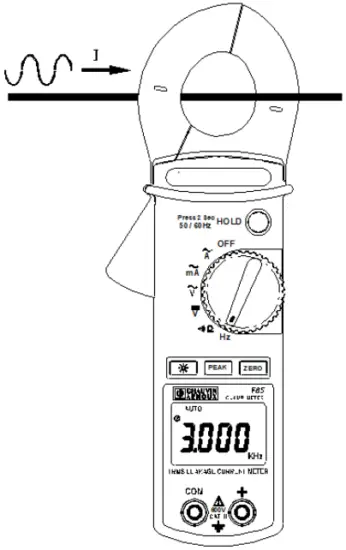 Open the clamp by pressing the trigger.
Place the clamp around the active conductors (Phase conductors and Neutral) and release the trigger; check that the clamp is properly closed.
Read the measurement result on the display unit.
Note: The frequency measurement cannot be made if the clamp-on meter detects both a current measurement and a voltage measurement.
SPECIFICATIONS
5.1. GENERAL
Only values with tolerances or stated limits are guaranteed. Values without tolerances are stated for information only.
5.2. CHARACTERISTICS
The precision is ± [% of reading (L) + a number of representation units (digits or D)] under the reference conditions (see Appendix).
5.2.1. AC CURRENT (AUTOMATIC RANGES)
| Ranges | Resolution | Accuracy |
| 10:00 AM | 1 mA | 1.2 % ± 5 cts (50-60 Hz) 2.5 % ± 5 cts (60-500 Hz) F65: 3.5 % ± 10 cts (500-3 kHz) |
| 80 A | 10 mA | |
| 80 – 100 A | 10 mA | 5 % ± 5 cts (50-60 Hz) |
Overload protection: 150 Arms
F65: RMS measurement (Rooth Mean Square value)
5.2.2. mAC CURRENT (AUTOMATIC RANGES)
| Ranges | Resolution | Accuracy |
| 60 mA | 10 µA | 1.2 % ± 5 cts (50-60 Hz) 2.5 % ± 5 cts (60-500 Hz) F65: 3.5 % ± 10 cts (500-3 kHz) |
| 600 mA | 100 µA |
Overload protection: 150 A
F65: RMS measurement (Rooth Mean Square value)
5.2.3. AC VOLTAGE (AUTOMATIC RANGES)
| Range | Resolution | Accuracy |
| 600 V | 0.1 V | 1.0 % ± 5 cts (50-60 Hz) 1.2 % ± 5 cts (60-500 Hz) F65: 2.5 % ± 5 cts (500-3 kHz) |
Input impedance: 1 MΩ
Overload protection: 660 Vrms
F65: RMS measurement (Rooth Mean Square value)
5.2.4. DC VOLTAGE (AUTOMATIC RANGES)
| Range | Resolution | Accuracy |
| 600 V | 0.1 V | 1.0 % ± 2 cts |
Input impedance: 1 MΩ
Overload protection: 660 Vrms
F65: RMS measurement (Rooth Mean Square value)
5.2.5. RESISTANCE (Ω) AND CONTINUITY ![]()
| Range | Resolution | Accuracy |
| 1 kΩ | 0.1 Ω | 1 % + 3 cts |
Max. voltage: 3.3 VDC during the measurement
Overload protection: 600 Vrms
Continuity selection threshold: R < 35 Ω
5.2.6. FREQUENCY (AUTOMATIC RANGES)
| Function | Ranges | Resolution | Accuracy |
| A-Hz | 5-100 Hz | 0.1 Hz | 0.5 % ± 2 cts |
| A-Hz | 100-1 kHz | 1 Hz | |
| V-Hz | 5-100 Hz | 0.1 Hz | 0.5 % ± 2 cts |
| V-Hz | 100-1 kHz | 1 Hz |
Frequency measurement for currents greater than10 mA AC.
Frequency measurement for voltages greater than 5 V AC.
5.2.7. SAFETY
IEC 61010-1, IEC 61010-2-032 and IEC 61010-2-033:
- Insulation: class III
- Pollution level: 2
- Altitude < 2000 m
- Installation category: CAT III 300 V
5.2.8. GENERAL INFORMATION
Digital display unit
4 LCD digits with max. reading of 9,999 points.
Overload
If a reading overshoots the range, the ![]() symbol is displayed.
symbol is displayed.
Battery Low indicator![]() is displayed when the voltage delivered by the battery is less than the operating voltage.
is displayed when the voltage delivered by the battery is less than the operating voltage.
Sampling
2 measurements/s for the digital display, and 100 ms for the MAX function.
Degree of protection of the enclosure
IP 30 as per NF EN 60529
Maximum opening of jaws
Ø 28 mm
Dimensions
(L x l x H) : 218 x 64 x 30 mm
Weight
280 g (with batteries)
5.3. ENVIRONMENT
5.3.1. TEMPERATURE
Operation: 0°C to 40°C, < 80 % RH
Storage: -10°C to 60°C, < 70 % RH
5.3.2. EMC
Emissions and immunity in an industrial setting compliant with EN 61326-1
5.3.3. DELIVERY CONDITION
A Leakage Clamp-on Meter F65 delivered in a box with:
– 1 operating manual
– 1 set of measuring cords (D4 mm, one black and one red)
– 2 1.5 V AAA or LR03 batteries
– 1 carrying bag
APPENDIX: Reference conditions
Sine-wave signal:
– Frequency from 48 to 65 Hz
– No DC component
– Temperature 23°C ± 5°C, RH < 80 %
– External magnetic field < 40 A/m
– No alternating magnetic field
– Conductor being measured centered (in A)
– Specifications are given for values from 5 to 100 % of each range.
Note: For a crest factor CF between 1.4 and 3 at full scale, add 1 % to these specifications.
WARRANTY
This equipment is warranted 3 years against defects in materials and workmanship.
During the warranty period, the instrument may be repaired only by the maker, who shall be free to decide whether to repair or replace all or part of the instrument. If the equipment is returned to the maker, the cost of transport to the maker is borne by the customer.
The warranty does not cover the following cases:
- Improper use of the hardware or use in association with incompatible equipment,
- Modification of the equipment without the explicit authorization of the maker’s technical staff,
- Work done by a person not approved by the maker,
- Adaptation to a particular application not anticipated in the definition of the equipment or in the operating instructions,
- Impact, fall, or flood.
The contents of this manual may not be reproduced in any form without our permission.
Note: warranty does not cover the magnetic head gap.
![]()
![]()
FRANCE
Chauvin Arnoux
12-16 rue Sarah Bernhardt
92600 Asnières-sur-Seine
Tél : +33 1 44 85 44 85
Fax : +33 1 46 27 73 89
[email protected]
www.chauvin-arnoux.com
INTERNATIONAL
Chauvin Arnoux
Tél : +33 1 44 85 44 38
Fax : +33 1 46 27 95 69
Our international contacts
www.chauvin-arnoux.com/contacts
691435B00 – Ed. 1 – 03/2021 © Chauvin Arnoux
– All rights reserved and reproduction prohibited


