![]() 83196 Luminaire
83196 Luminaire
Instruction Manual
Mounting Instruction
Item no: 83196
- Find a clear area in which you can work.
- Unpack fixture and glass from carton.
- Carefully review instructions prior to assembly.
Shut off electrical current before starting. If the fixture you are replacing is turned on and off by a wall switch, simply turn the switch off. If not, remove the appropriate fuse (or open the circuit breakers) until the fixture is dead.DO NOT restore current – either by fuse, breaker, or switch until the new fixture is completely wired and in place.
- Determine the desired height the pendant will be installed.
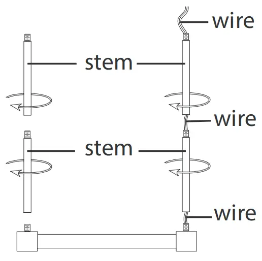
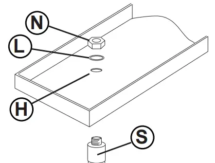
- The fixture is supplied with assorted stem sizes. Determine what combinations of stems are needed to achieve desired length. see Drawing 1
- Slip stems over wire and thread first stem onto top of pendant, longest stem first. Repeat this process until all required stems are threaded together.
- Slip wire through center hole of canopy swivel and thread swivel onto the top of the last stem installed.
SAFETY WARNING: READ WIRING AND GROUNDING INSTRUCTIONS (I.S. 18) AND ANY ADDITIONAL DIRECTIONS. TURN POWER SUPPLY OFF DURING INSTALLATION. IF NEW WIRING IS REQUIRED, CONSULT A QUALIFIED ELECTRICIAN OR LOCAL AUTHORITIES FOR CODE REQUIREMENTS.
Make electrical connections from supply wire to fixture lead wires. Refer to instruction sheet (I.S. 18) and follow all instructions to make all necessary wiring connections. Then refer back to this sheet to complete installation of this fixture.
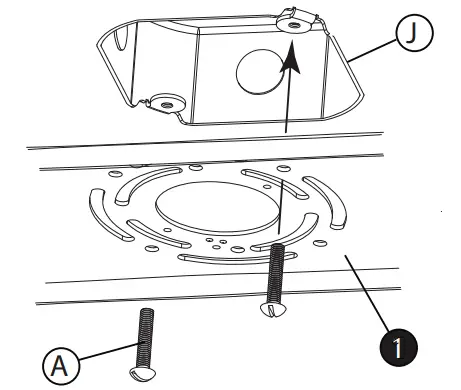
Mounting Plate Installation Instructions
ADDITIONAL ANCHOR POINTS
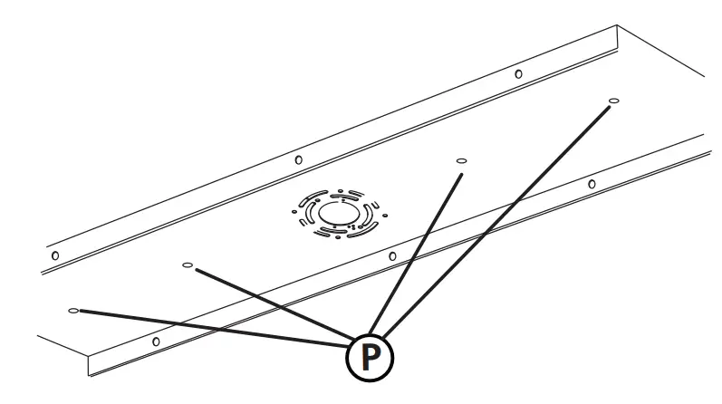
IT IS RECOMMENDED THAT THIS FIXTURE BE MOUNTED INDEPENDENTLY OF THE JUNCTION BOX. THE MOUNTING PLATE MUST BE MOUNTED TO THE CEILING USING APPROPRIATE MOUNTING HARDWARE AND BE MOUNTED TO A JOIST OR OTHER STRUCTURE THAT WILL PROPERLY SUPPORT THE WEIGHT.
NOTE: USE THE APPROPRIATE HARDWARE FOR ANCHORING. DIFFERENT MATERIALS REQUIRE DIFFERENT HARDWARE. IT IS UP TO THE INSTALLER TO ACQUIRE THE REQUIRED HARDWARE AND TO ENSURE THE FIXTURE IS INSTALLED INDEPENDENTLY OF THE JUNCTION BOX.
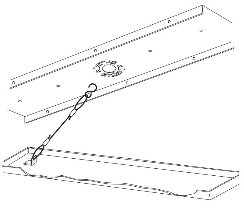
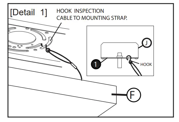
This luminaire is supplied with inspection cablesthat can be hooked onto the canopy to ease the wiring process during installation
see Drawing 1.
After wiring is completed see mounting instructions supplied to finish installation.
wiring grounding instructions
Drawing 1- Flush Moun
Drawing 2-Chain Hun
Drawing 3- Post-Mount
Indoor Fixtures
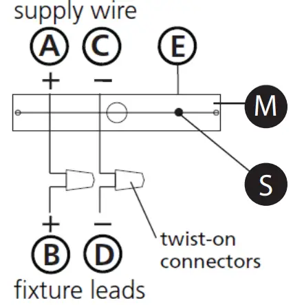
- Connect positive supply wire (A) (typically black or the smooth, unmarked side of the two-conductor cord) to positive fixture lead (B)with appropriately sized twist on connector – see Drawings 1 or 2.
- Connect negative supply wire (Cl (typically white or the ribbed, marked side of the two-conductor cord) to negative fixture lead (D).
- Please refer to the grounding instructions below to complete all electrical connections
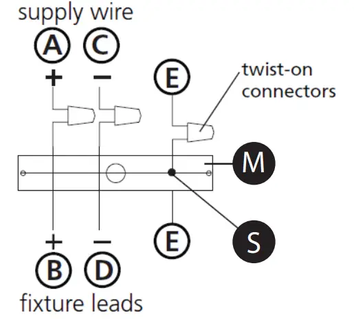
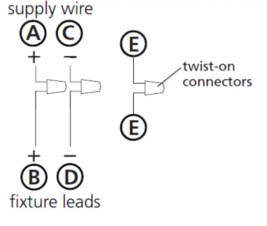
- Connect positive supply wire (A) (typically black or the smooth unmarked side of the two-conductor cord) to positive fixture lead (B) with appropriately sized twist on connector – see Drawings 2 or 3.
- Connect negative supply wire (Cl (typically white or the ribbed, markeside of the two-conductor cord) to negative fixture lead (D).
- Cover open end of connectors with silicone sealant to form a watertight seal. If installing a wall mount fixture, use caulk to seal gaps between the
fixture mounting plate (backpla te) and the wall. This will help prevenwater from entering the out let box. If the wal I surface is lap siding, ucaulk and a fixture mounting platform specially. - Please refer to the grounding instructions below to complete allelectrical connections.
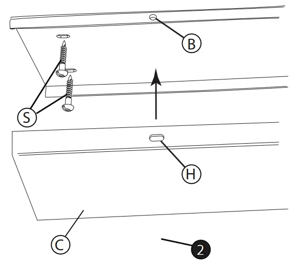
For positive grounding in a 3-wire electrical system, fasten the fixture ground wire ( E) (typically copper or green plastic coated) to the fixture mounting strap (M) with the ground screw (S) see Drawing 1.
Note: On straps for screw supported fixtures, first install the two mounting
Loop fixture ground wire (E) (typicallycoppe r or green plastic coated) under the head of the ground screw (S) on fixture mounting strap (M) and connect to the loose end of the fixture ground wire directly to the ground wire of the building system with appropriately sized twist-on connectors-see Drawing 2.
Post-Mou nt Fixtures
Connect fixture ground wire (E) (typically copper or green plastic coated) to power supply ground with appropriately sized twist-on connector inside post. Cover open end of connector with silicone sealant to form a watertight seal – see Drawing 3.
Larkliving.com


