![]() Installation Guide
Installation Guide
ACC-SVN150G-EN
Accessory Electric Heat
Foundation Packaged Rooftop Units
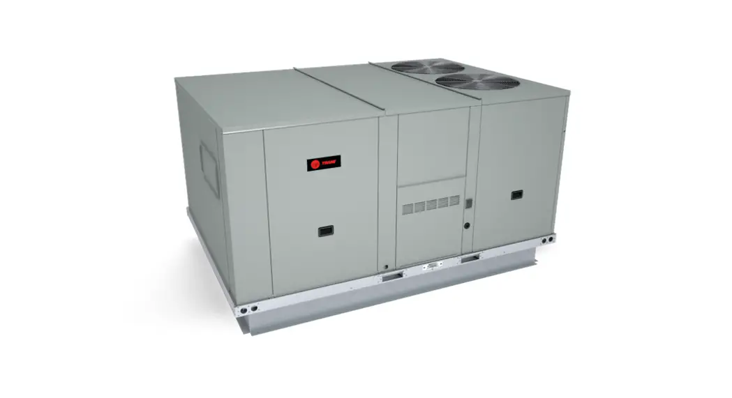
15 to 25 Tons
| BAYHTFB318* BAYHTFC336* BAYHTFD336* BAYHTFC354* BAYHTFD354* BAYHTFC372* BAYHTFD372* BAYHTFB418* BAYHTFC436* BAYHTFD436* | BAYHTFC454* BAYHTFD454* BAYHTFC472* BAYHTFD472* BAYHTFBW18* BAYHTFCW36* BAYHTFDW36* BAYHTFCW54* BAYHTFDW54* BAYHTFCW72* | BAYHTFDW72* BAYHTFBK18* BAYHTFCK36* BAYHTFCK54* BAYHTFDK18* BAYHTFDK36* BAYHTFDK54* BAYHTFDK72* |
BAYHTFB318 Accessory Electric Heat Foundation Packaged Rooftop
![]() SAFETY WARNING
SAFETY WARNING
Only qualified personnel should install and service the equipment. The installation, starting up, and servicing of heating, ventilating, and air-conditioning equipment can be hazardous and requires specific knowledge and training. Improperly installed, adjusted or altered equipment by an unqualified person could result in death or serious injury. When working on the equipment, observe all precautions in the literature and on the tags, stickers, and labels that are attached to the equipment.
Introduction
Read this manual thoroughly before operating or servicing this unit.
Warnings, Cautions, and Notices
Safety advisories appear throughout this manual as required. Your personal safety and the proper operation of this machine depend upon the strict observance of these precautions.
The three types of advisories are defined as follows:
![]() WARNING
WARNING
Indicates a potentially hazardous situation which, if not avoided, could result in death or serious injury.![]() CAUTION
CAUTION
Indicates a potentially hazardous situation which, if not avoided, could result in minor or moderate injury. It could also be used to alert against unsafe practices.
NOTICE
Indicates a situation that could result in equipment or property-damage only accidents.
Important Environmental Concerns
Scientific research has shown that certain man-made chemicals can affect the earth’s naturally occurring stratospheric ozone layer when released to the atmosphere. In particular, several of the identified chemicals that may affect the ozone layer are refrigerants that contain Chlorine, Fluorine and Carbon (CFCs) and those containing Hydrogen, Chlorine, Fluorine and Carbon (HCFCs). Not all refrigerants containing these compounds have the same potential impact to the environment. Trane advocates the responsible handling of all refrigerantsincluding industry replacements for CFCs and HCFCs such as saturated or unsaturated HFCs and HCFCs.
Important Responsible Refrigerant Practices
Trane believes that responsible refrigerant practices are important to the environment, our customers, and the air conditioning industry. All technicians who handle refrigerants must be certified according to local rules. For the USA, the Federal Clean Air Act (Section 608) sets forth the requirements for handling, reclaiming, recovering and recycling of certain refrigerants and the equipment that is used in these service procedures. In addition, some states or municipalities may have additional requirements that must also be adhered to for responsible management of refrigerants. Know the applicable laws and follow them.
![]() WARNING
WARNING
Proper Field Wiring and Grounding Required!
Failure to follow code could result in death or serious injury.
All field wiring MUST be performed by qualified personnel. Improperly installed and grounded field wiring poses FIRE and ELECTROCUTION hazards. To avoid these hazards, you MUST follow requirements for field wiring installation and grounding as described in NEC and your local/state/national electrical codes.
WARNING
Personal Protective Equipment (PPE) Required!
Failure to wear proper PPE for the job being undertaken could result in death or serious injury.
Technicians, in order to protect themselves from potential electrical, mechanical, and chemical hazards, MUST follow precautions in this manual and on the tags, stickers, and labels, as well as the instructions below:
- Before installing/servicing this unit, technicians MUST put on all PPE required for the work being undertaken (Examples; cut resistant gloves/sleeves, butyl gloves, safety glasses, hard hat/bump cap, fall protection, electrical PPE and arc flash clothing). ALWAYS refer to appropriate Safety Data Sheets (SDS) and OSHA guidelines for proper PPE.
- When working with or around hazardous chemicals, ALWAYS refer to the appropriate SDS and OSHA/GHS (Global Harmonized System of Classification and Labelling of Chemicals) guidelines for information on allowable personal exposure levels, proper respiratory protection and handling instructions.
- If there is a risk of energized electrical contact, arc, or flash, technicians MUST put on all PPE in accordance with OSHA, NFPA 70E, or other country-specific requirements for arc flash protection, PRIOR to servicing the unit. NEVER PERFORM ANY SWITCHING, DISCONNECTING, OR VOLTAGE TESTING ITHOUT PROPER ELECTRICAL PPE AND ARC FLASH CLOTHING.
ENSURE ELECTRICAL METERS AND EQUIPMENT ARE PROPERLY RATED FOR INTENDED VOLTAGE.
![]() WARNING
WARNING
Follow EHS Policies!
Failure to follow instructions below could result in death or serious injury.
- All Trane personnel must follow the company’s Environmental, Health and Safety (EHS) policies when performing work such as hot work, electrical, fall protection, lockout/tagout, refrigerant handling, etc. Where local regulations are more stringent than these policies, those regulations supersede these policies.
- Non-Trane personnel should always follow local regulations.
Copyright
This document and the information in it are the property of Trane, and may not be used or reproduced in whole or in part without written permission. Trane reserves the right to revise this publication at any time, and to make changes to its content without obligation to notify any person of such revision or change.
Trademarks
All trademarks referenced in this document are the trademarks of their respective owners.
Revision History
Model number updates in the General Information and Installation chapter.
General Information
These instructions cover the installation of accessory electric heat in Cooling Only units. Limit control settings are listed in the following chart.
Table 1. Limit control settings (in Deg. F)
| Heater Rated Voltage | Downflow and Horizontal |
| 240 | 160 |
| 460 | 150 |
| 600 | 150 |
The following tables show the air temperature rise across the electric heaters:
Table 2. Air temperature rise across electric heaters -cooling – 60Hz
| kW | Stages | ECC180 NOM. CFM 6000 | ECC210 NOM. CFM 7000 | ECC240 NOM. CFM 8000 | ECC300 NOM. CFM 9000 |
| 18 | 1 | 9.5 | |||
| 36 | 1 | 19.0 | 16.3 | 14.2 | 12.6 |
| 54 | 2 | 28.5 | 24.4 | 21.3 | 19.0 |
| 72 | 2 | – | 32.5 | 28.5 | 25.3 |
Table 3. Air temperature rise across electric heaters cooling- 50Hz
| kW | Stages | EA*180AD NOM. CFM 6000 | EA*210AD NOM. CFM 7000 | EA*240AD NOM. CFM 8000 | EA*300AD NOM. CFM 9000 |
| 18 | 2 | 9.5 | – | – | – |
| 36 | 2 | 19 | 20.3 | 16.3 | 16.3 |
| 54 | 2 | 28.5 | 30.5 | 24.5 | 24.5 |
| 72 | 2 | 37.9 | 40.6 | 32.5 | 32.5 |
Unit Inspection
To protect against loss due to damage incurred in transit, perform inspection immediately upon receipt of the unit.
Check carefully for shipping damage. If any damage is found, report it immediately, and file a claim against the transportation company.
Exterior Inspection
If the job site inspection reveals damage or material shortages, file a claim with the carrier immediately. Specify the type and extent of the damage on the bill of lading before signing. Notify the appropriate sales representative.
Important: Do not proceed with installation of a damaged unit without sales representative approval.
- Verify that the nameplate data matches the sales order and bill of lading.
- Verify that the unit is properly equipped and there are no material shortages.
- Verify the power supply complies with the unit nameplate specifications.
Inspection for Concealed Damage
Inspect the components for concealed damage as soon as possible after delivery and before it is stored.
If concealed damage is discovered:
- Notify the carrier’s terminal of the damage immediately by phone and by mail.
- Concealed damage must be reported within 15 days.
- Request an immediate, joint inspection of the damage with the carrier and consignee.
- Stop unpacking the unit.
- Do not remove damaged material from receiving location.
- Take photos of the damage, if possible.
- The owner must provide reasonable evidence that the damage did not occur after delivery.
Parts List
Table 4. Parts list
| Quantity | Description |
| 1 | Heater element assembly |
| 1 | Heater control assembly |
| 31 | Sheet metal screws (3/4-in.) |
| 4 | Screws (1/2-in. with blunt point) |
| 1 | Hinged access panel with support pre-assembled |
| 1 | Wiring diagram(s) |
| 1 | Foam tape |
| 1 | Conduit plates (one or more with different size holes) |
| 1 | Wire ties (with eye for screw) |
Installation
Removing Heater from Packaging
- Remove all cardboard supports from the box.
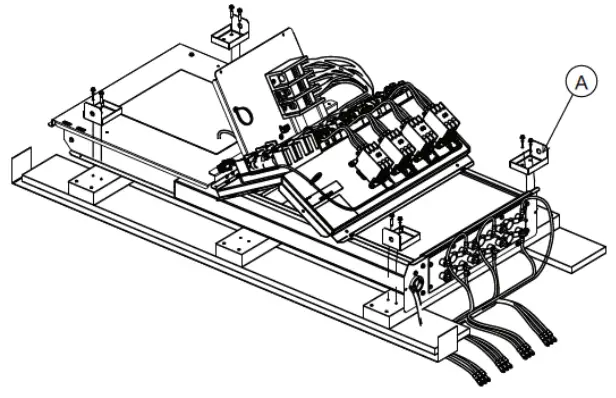
- Unfasten and discard the four L-brackets (A) along with the eight screws holding the heater assembly to the wooden base.
Figure 1. Remove L brackets
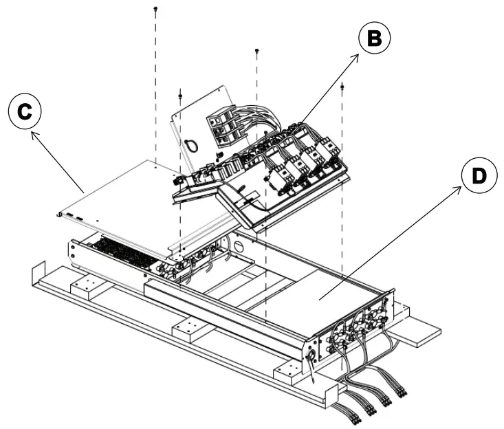
- Remove and discard five screws in order to separate the control panel (B) and the hinged access door (C) from the electric heater, as shown in figure below.
Figure 2. Remove screws and cardboard pad
- Remove the cardboard pad (D) from the top of the front heater element before installing the heater.
Heater Installation
![]() WARNING
WARNING
Hazardous Voltage!
Failure to disconnect power before servicing could result in death or serious injury.
Disconnect all electric power, including remote disconnects before servicing. Follow proper lockout/tagout procedures to ensure the power can not be inadvertently energized. Verify that no power is present with a voltmeter.
- Open and lock unit disconnect.
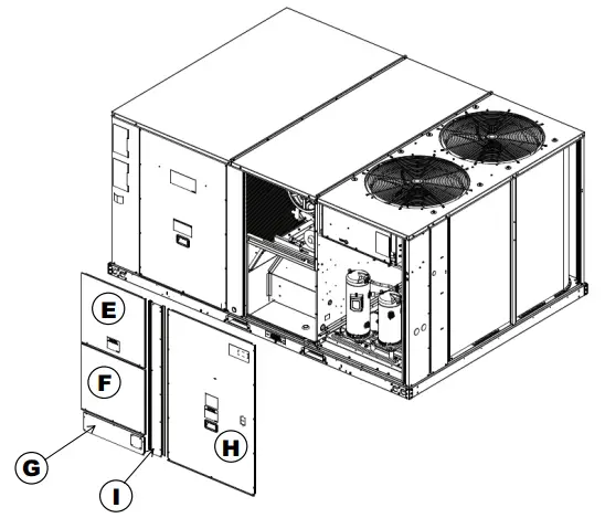
- Remove indoor fan panel (E), electric heater panel (F), power conduit entry panel (G), compressor access panel (H), and vertical post (I). See figure below.
Figure 3. Remove panels and post
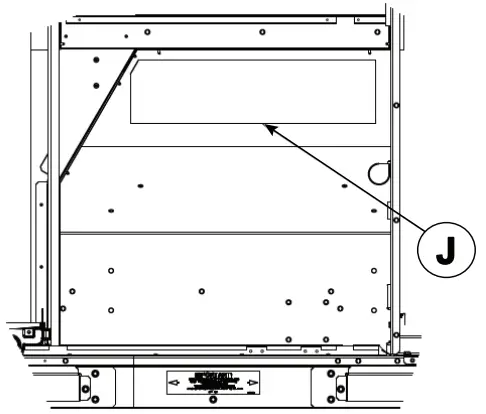
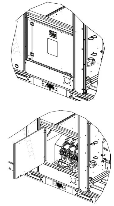
- Remove the pre-cut piece of insulation (J) located over the removable heater access panel. See figure below.
Figure 4. Remove insulation
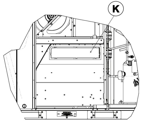
- Cut or break tabs around the perimeter of the removable panel (K) exposed in previous step, and discard panel. See figure below.
Important: On downflow units, ensure panel does not fall inside unit and into duct work.
Figure 5. Remove heater access panel
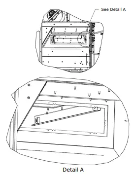
- Through the opening, locate the bracket attached to the indoor fan panel on top (see figure below). Insert heater at an angle into opening while holding the rear side higher than the front. As heater is inserted through the opening, this insures the heater flanges are above the bracket flanges in the unit. The heater flanges rest on the flanges of the support brackets located inside and to the rear of the area where heater is being installed.
Slide heater assembly over the flanges, all the way through.
Note: Make sure the flange side of the heater back plate is on top.
Figure 6. Support brackets inside the opening
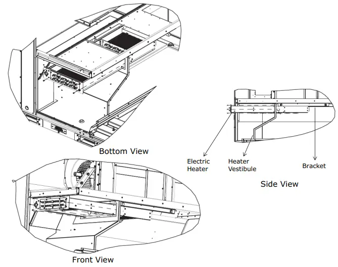
- Secure heater with ¾-inch sheet metal screws provided in the ship-with packet, shooting through the pre-drilled holes. See figure below.
Figure 7. Slide heater into opening
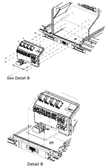
- Using the remaining screws, install the heater control assembly on to the vestibule as illustrated below.
Figure 8. Install control assembly Important: Use the wiring diagram provided to perform following steps.
 - Attach the wires hanging from the heater to the corresponding contactors.
Note: The heater opening on the left carries power wires from the far heater and will be sealed off for the 18kW model since there is one row of element in the front. - Connect the low voltage plug to the mating plug in the unit control box.
- Uncoil the power wire harness in the cardboard sleeve provided with the kit. Route and secure the leads, one end to the unit cooling fuse in the heater control panel and the other end to the terminal block in the unit control box.
Note: The wires need to be routed through holes provided in the outdoor section partition panel.
Figure 9. Connect heater control panel
- Attach the post and the power conduit entry panel back on to the unit. Remove the plate covering the conduit entry opening.
Note: There are a number of conduit plates provided.
Choose the one with a hole of the correct size for the conduit that will be used.. - Apply foam tape around the perimeter of the conduit plate to provide a water tight seal, then connect conduit to the terminal block in the electric heater control panel.
Ground unit at grounding lug provided on electric heater control panel assembly. - Attach the hinged access door assembly. Position door with outer tab flush against the post. Fasten the door support to the power conduit entry panel on the bottom and the gusset plate on the top rear side of the support.
See figure below.
Figure 10. Install hinged access door assembly
- Replace all the panels removed in step 2.
- For Through the Base Electric Connections:
Customer conduit connects to the unit disconnect. The power wires from the disconnect are routed under the unit control box, along the outdoor section partition panel and into the electric heater section. These wires need to be connected to the terminal block provided in the electric heater controls assembly.
Refer to the Installation Instructions provided with the Through the Base Electric Accessory kit for more details.
 Important: Use the wiring diagram provided to perform following steps.
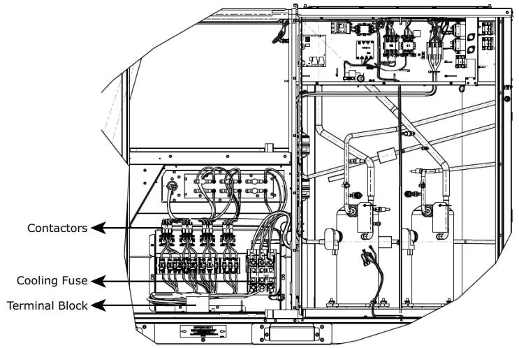
| Tons | Unit Model Number | Heater Model Number | Heater kW Rating | Control Stages | Standard Indoor Motor | Oversized Indoor Motor | ||
| MCA | Max Fuse Size or Max Circuit Breaker | MCA | Max Fuse Size or Max Circuit Breaker00 | |||||
| 208/230 Volts Three Phase | ||||||||
| 15 | ECC180A3 | BAYHTFB318A BAYHTFC336A BAYHTFC354A | 13.5118 27136 40.5/54 | 1 2 2 | 79 108/122 155/144 | 100 110/125 175 | 85 115/130 162/151 | 110 125/150 175 |
| 18. | ECC210A3 | BAYHTFC336A BAYHTFC354A BAYHTFC372A | 27/36 40.5/54 54/72 | 2 2 2 | 1151130 162/151 172/195 | 125/150 175 200/225 | 125/139 172/161 181/204 | 125/150 175 200/225 |
| 20 | ECC240A3 | BAYHTF0336A BAYHTF0354A BAYHTFD372A | 27/36 40.5/54 54/72 | 2 2 2 | 115/130 162/151 172/195 | 125/150 175 200/225 | 125/139 172/161 181/204 | 125/150 175 200/225 |
| 25 | ECC300A3 | BAYHTFD336A BAYHTFD354A BAYHTFD372A | 27/36 40.5/54 54/72 | 2 2 2 | 133/139 172/161 181/204 | 175 175 200/225 | 140/147 180/169 189/212 | 175 200/175 200/225 |
| 460 Volts Three Phase | ||||||||
| 15 | ECC180A4 | BAYHTFB418A BAYHTFC436A BAYHTFC454A | 18 36 54 | 1 2 2 | 36 61 72 | 45 70 90 | 39 64 75 | 50 70 90 |
| 18. | ECC210A4 | BAYHTFC436A BAYHTFC454A BAYHTFC472A | 36 54 72 | 2 2 2 | 64 75 97 | 70 90 110 | 68 79 101 | 70 90 110 |
| 20 | ECC240F4 | BAYHTFD436A BAYHTFD454A BAYHTFD472A | 36 54 72 | 2 2 2 | 64 75 97 | 70 90 110 | 68 79 101 | 70 90 110 |
| 25 | ECC300A4 | BAYHTFD436A BAYHTFD454A BAYHTFD472A | 36 54 72 | 2 2 2 | 68 79 101 | 70 90 110 | 72 83 105 | 80 90 110 |
| 575 Volts Three Phase | ||||||||
| 15 | ECC180AW | BAYHTFBW18A BAYHTFCW36A BAYHTFCW54A | 18 36 54 | 1 2 2 | 30 49 57 | 35 50 70 | 32 51 60 | 40 60 70 |
| 18. | ECC210AW | BAYHTFCW36A BAYHTFCW54A BAYHTFCW72A | 36 54 72 | 2 2 2 | 51 60 77 | 60 70 90 | 55 64 81 | 60 70 90 |
| 20 | ECC240AW | BAYHTFOW36A BAYHTFOW54A BAYHTFDVV72A | 36 54 72 | 2 2 2 | 51 60 77 | 60 70 90 | 55 64 81 | 60 70 90 |
| 25 | ECC300AW | BAYHTFDW36A BAYHTFDW54A BAYHTFDW72A | 36 54 72 | 2 2 2 | 55 64 81 | 60 70 90 | 58 66 84 | 60 70 90 |
Values do not include power exhaust accessory.
Table 6. Unit wiring with electric heat (single point connection) – 50Hz
| Tons | Unit Model Number | Heater Model Number | Heater kW Rating | Control Stages | Standard Indoor Motor | Oversized Indoor Motor | ||
| MCA | Max Fuse Size or Max Circuit Breaker | MCA | Max Fuse Size or Max Circuit Breakerla) | |||||
| 380415 Volts Three Phase | ||||||||
| 15 | EAC180AD | BAYHTFBK18A | 11.3/13.5 | 1 | 42 | 50 | – | – |
| BAYHTFCK36A | 22.6/26.9 | 2 | 50 | 50 | – | – | ||
| BAYHTFCK54A | 33.8/40.4 | 2 | 71 | 80 | – | – | ||
| 18. | EAC210AD | BAYHTFCK36A | 22.6/26.9 | 2 | 50 | 70 | 53 | 70 |
| BAYHTFCK54A | 33.8/40.4 | 2 | 71 | 80 | 74 | 80 | ||
| BAYHTFCK72A | 45.1/53.8 | 2 | 93 | 100 | 96 | 100 | ||
| 20 | EAC240AD | BAYHTFDK36A | 22.6/26.9 | 2 | 62 | 80 | – | – |
| BAYHTFDK54A | 33.8/40.4 | 2 | 74 | 80 | – | – | ||
| BAYHTFDK72A | 45.1/53.8 | 2 | 96 | 100 | – | – | ||
| 25 | EAC270AD | BAYHTFDK36A | 22.6/26.9 | 2 | 62 | 80 | – | – |
| BAYHTFDK54A | 33.8/40.4 | 2 | 74 | 80 | – | – | ||
| BAYHTFDK72A | 45.1/53.8 | 2 | 96 | 100 | – | – | ||
(a) Values do not include power exhaust accessory.
Trane and American Standard create comfortable, energy efficient indoor environments for commercial and residential applications. For more information, please visit trane.com or americanstandardair.com.
Trane and American Standard have a policy of continuous product and product data improvement and reserve the right to change design and specifications without notice. We are committed to using environmentally conscious print practices.
ACC-SVN150G-EN 03 Dec 2022
Supersedes ACC-SVN150F-EN (April 2020)
©2022


