![]()
TL70 Modular Tower Light
Instruction Manual
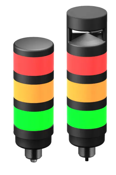
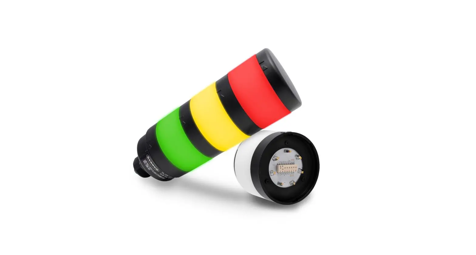
Banner’s TL70 Tower Light is a 70 mm, modular LED indicator with extremely bright and uniform light. The modularity gives the user flexibility to customize tower lights as needed and change positions in the field. The TL70 is also available preassembled for easy installation.
- Light segments have user-selectable solid ON or flashing
- Up to six colors, or five colors plus audible, in one device
- Rugged, water-resistant IP65 housing with UV-stabilized material
- Bright, uniform indicator segments appear gray when off to eliminate false indications from ambient light
- Several connection options to choose from include M12 quick-disconnect cabled, and terminal-wired
Models
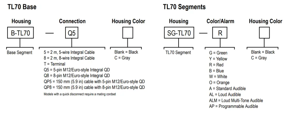
Select the 5-pin base for tower light configurations of up to 4 modules. Select the 8-pin base for tower light configurations of up to 6 modules.
- Example base model number: B-TL70-Q5
- Example light segment model number: SG-TL70-G
- Example audible segment model number: SG-TL70-A
TL70 Pre-Assembled Models
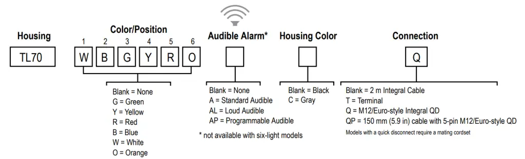
- Example pre-assembled model number: TL70GYRAQ.
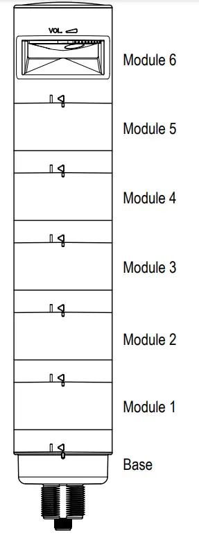
Configuring the Modules
![]() Turn on the appropriate DIP switch to set the order of the components, counting up from the tower light’s base.
Turn on the appropriate DIP switch to set the order of the components, counting up from the tower light’s base.
| Assembly Options | DIP Switches | ||||||||
| 1 | 2 | 3 | 4 | 5 | 6 | 7 | 8 | ||
|
Light and Standard Audible Components | Module 1 | ON | |||||||
| Module 2 | ON | ||||||||
| Module 3 | ON | ||||||||
| Module 4 | ON | ||||||||
| Module 5 | ON | ||||||||
| Module 6 | ON | ||||||||
| Light Module Flash Rate | 3 Hz | ON | OFF | ||||||
| 1.5 Hz | ON | ON | |||||||
| Solid On* | OFF | OFF |
|
Standard Audible Module Settings | Pulse 1.5 Hz | ON | OFF | ||||||
| Chirp Alarm | ON | ON | |||||||
| Siren Alarm | OFF | ON | |||||||
| Continuous Alarm* | OFF | OFF |
| Assembly Options | DIP Switches | ||||||||||
| 1 | 2 | 3 | 4 | 5 | 6 | 7 | 8 | 9 | 10 | ||
|
Loud Audible Module Settings | Pulse 1.5 Hz | ON | OFF | ||||||||
| Chirp Alarm | ON | ON | |||||||||
| Siren Alarm | OFF | ON | |||||||||
| Continuous Alarm* | OFF | OFF | |||||||||
| Low Intensity* | OFF | OFF | |||||||||
| Med. Intensity | ON | OFF | |||||||||
| Med./Loud Intensity | OFF | ON | |||||||||
| Loud Intensity | ON | ON | |||||||||
- Factory default setting
Programming the Audible Tower Module
Loading Files into the SG-TL70-AP
The SG-TL7-AP has 4MB of onboard flash memory and can playback any WAV or MP3 audio file that is 4MB or smaller. If the file is too large, a program such as Audacity can be used to compress or shorten the file to decrease the size.
Multiple files can be loaded onto the SG-TL70-AP. Files playback according to the file name in alpha-numeric order.![]() Note: Add a number to the beginning of the file name to create the order in which the files run. Files play consecutively without any pause.
Note: Add a number to the beginning of the file name to create the order in which the files run. Files play consecutively without any pause.
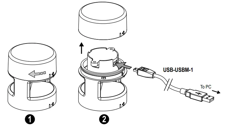
To program the module:
- Remove the module top cover by rotating counterclockwise.
- Connect the programming cable (USB-USBM-1) from the PC’s USB connection to the USB mini-connection of the audible module.
The SG-TL70-AP is recognized by the PC as a USB flash drive. The default drivers for a USB drive are assigned to the device, as well as a unique disk drive letter assignment (such as D:). - Drag-and-drop the audio files that are saved on the PC to the USB drive location.
- Assign numbers to each file to designate their playback order, otherwise files playback in alpha-numeric order.
- Remove the cable from the audio module.
- Re-install the top cover by aligning the protruding alignment marks and turning clockwise.
- The audible module is now ready for use with a compatible TL70 DC Base or Universal Voltage AC Base.
When the selected Input Channel is activated, the audible module begins playing the files in sequential order.
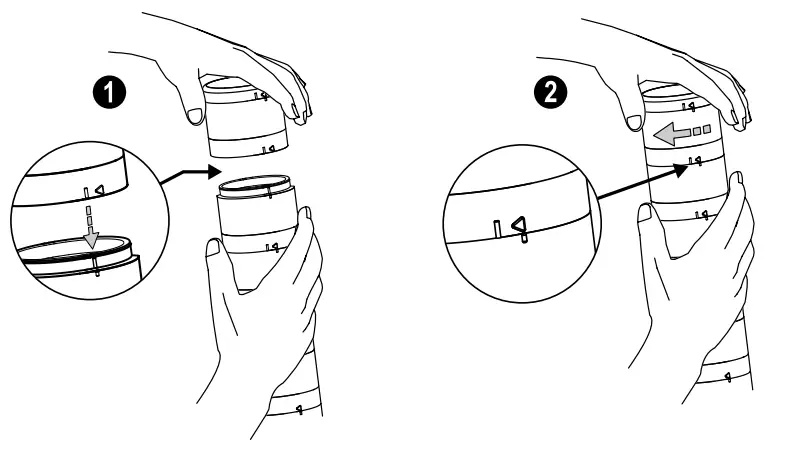
Assembling the Modules
P/N 182214 Rev. K
www.bannerengineering.com – Tel: + 1 888 373 6767
To assemble the modules:
- Align the notches on each module and press them together.
- Rotate the top module clockwise to lock into place (notches shown in the locked position).
Wiring Diagrams
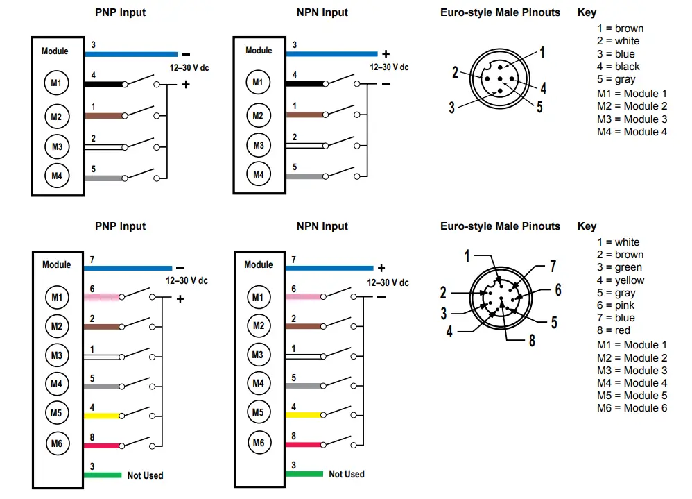
![]() Note: Models SG-TL70-ALM and SG-TL70-ALMC are not compatible with NPN input wiring.
Note: Models SG-TL70-ALM and SG-TL70-ALMC are not compatible with NPN input wiring.
Terminal Block Key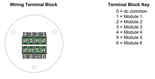
Specifications
Supply Voltage and Current
12 V DC to 30 V DC
| Indicator Color or Audible Model | Maximum Current (mA) | ||
| at 12 V DC | at 24 V DC | at 30 V DC | |
| Blue, Green, White | 420 | 200 | 150 |
| Red, Yellow, Orange | 285 | 145 | 120 |
| Standard Audible | 30 | 30 | 30 |
| Loud Audible (Intensity 1) | 30 | 28 | 25 |
| Loud Audible (Intensity 2) | 50 | 45 | 40 |
| Loud Audible (Intensity 3) | 165 | 90 | 75 |
| Loud Audible (Intensity 4) | 350 | 160 | 120 |
| Programmable Audible | 290 | 140 | 125 |
Supply Protection Circuitry
Protected against transient voltages
Indicators
1 to 6 colors depending on model (Green, Red, Yellow, Blue, White, and Orange)
LEDs are independently selected
Flash Rates: 1.5 Hz ±10% and 3 Hz ±10%
Indicator Response Time
Off Response: 150 µs (maximum) at 12 V DC to 30 V DC
On Response: 180 ms (maximum) at 12 V DC; 50 ms (maximum) at 30 V DC
Indicator Characteristics
| Color | Dominant Wavelength (nm) or Color Temperature (CCT) | Color Coordinates 1 | Lumen Output (Typical at 25 °C) | |
| x | y | |||
| Green | 525 nm | – | – | 92 |
| Red | 625 nm | – | – | 40 |
| Yellow | 590 nm | – | – | 22 |
| Blue | 470 nm | – | – | 32 |
| White | 5000 K | – | – | 125 |
| Orange | – | 0.66 | 0.33 | 33 |
Connections
5-pin M12 quick-disconnect connector, 8-pin M12 quick-disconnect connector, 150 mm (5.9 in) PVC cable with an M12 quick-disconnect connector, terminal block, or 2 m (6.5 ft) unterminated cable, depending on model
Terminal Block Models
14 to 28 AWG wire
Operating Conditions
–40 °C to +50 °C (–40 °F to +122 °F)
95% at +50 °C maximum relative humidity (non-condensing)
Environmental Rating
IEC IP65
Certifications![]()
Audible Alarm
Standard Audible: 2.6 kHz ± 250 Hz oscillation frequency; maximum intensity (typical) 92 dB at 1 m (3.3 ft)
Loud Audible: 2.6 kHz ± 250 Hz oscillation frequency; maximum intensity (typical) at 1 m (3.3 ft) (see table)
| DIP Switches | Max Intensity (Loud Audible) | |
| 9 | 10 | |
| ON | ON | Intensity 4: 101 dB |
| OFF | ON | Intensity 3: 99 dB |
| ON | OFF | Intensity 2: 92 dB |
| OFF | OFF | Intensity 1: 85 dB |
Audible Adjustment
Standard Audible: Rotate the cover until the desired volume is reached
Loud Audible Alarm: Select the desired volume using DIP switches 9 and 10
Typical Reduction in Sound Intensity with Audible Adjustment (maximum to minimum):
• Standard Audible: 8 dB
• Loud Audible: 16 dB
Construction
Bases, Segments, Covers: polycarbonate
Vibration and Mechanical Shock
Vibration: 10 Hz to 55 Hz, 0.5 mm peak-to-peak amplitude per IEC 60068-2-6
Shock: 15G 11 ms duration, half-sine wave per IEC 60068-2-27
Required Overcurrent Protection WARNING: Electrical connections must be made by qualified personnel in accordance with local and national electrical codes and regulations.
Overcurrent protection is required to be provided by end-product application per the supplied table.
Overcurrent protection may be provided with external fusing or via Current
Limiting, Class 2 Power Supply.
Supply wiring leads < 24 AWG shall not be spliced.
For additional product support, go to www.bannerengineering.com.
| Supply Wiring (AWG) | Required Overcurrent Protection (Amps) |
| 20 | 5.0 |
| 22 | 3.0 |
| 24 | 2.0 |
| 26 | 1.0 |
| 28 | 0.8 |
| 30 | 0.5 |
¹Refer to CIE 1931 chromaticity diagram or color chart, to show equivalent color with indicated color coordinates.
Dimensions
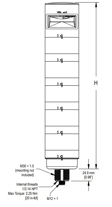
| Model | Height (H) |
| 1 light module | 87.6 mm (3.45 in) |
| 1 light module, 1 audible module | 144.3 mm (5.68 in) |
| 2 light modules | 137.3 mm (5.41 in) |
| 2 light modules, 1 audible module | 194 mm (7.64 in) |
| 3 light modules | 187 mm (7.36 in) |
| 3 light modules, 1 audible module | 243.7 mm (9.59 in) |
| 4 light modules | 236.7 mm (9.32 in) |
| 4 light modules, 1 audible module | 293.4 mm (11.55 in) |
| 5 light modules | 286.4 mm (11.28 in) |
| 5 light modules, 1 audible module | 343.1 mm (13.5 in) |
Accessories
Cordsets
| 5-Pin Threaded M12 Cordsets—Single Ended | ||||
| Model | Length | Style | Dimensions | Pinout (Female) |
| MQDC1-501.5 | 0.5 m (1.5 ft) | Straight | 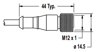 | 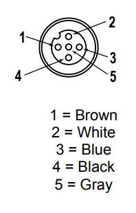 |
| MQDC1-506 | 2 m (6.5 ft) | |||
| MQDC1-515 | 5 m (16.4 ft) | |||
| MQDC1-530 | 9 m (29.5 ft) | |||
| MQDC1-506RA | 2 m (6.5 ft) | Right-Angle | 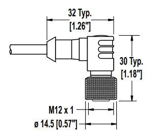 | |
| MQDC1-515RA | 5 m (16.4 ft) | |||
| MQDC1-530RA | 9 m (29.5 ft) | |||
| 5-Pin Threaded M12 Cordsets—Single Ended | ||||
| Model | Length | Style | Dimensions | Pinout (Female) |
| MQDC2S-806 | 2.04 m (6.7 ft) | Straight | | 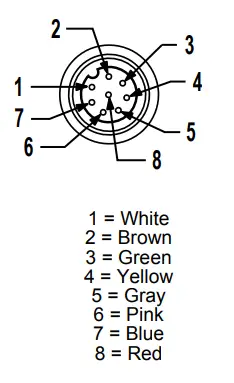 |
| MQDC2S-815 | 5.04 m (16.54 ft) | |||
| MQDC2S-830 | 10.04 m (32.95 ft) | |||
| MQDC2S-850 | 16 m (52.49 ft) | |||
| MQDC2S-806RA | 2 m (6.56 ft) | Right-Angle | | |
| MQDC2S-815RA | 5 m (16.4 ft) | |||
| MQDC2S-830RA | 10 m (32.81 ft) | |||
| MQDC2S-850RA | 16 m (52.49 ft) | |||
Mounting Brackets
All measurements are listed in millimeters unless noted otherwise.
SMB30A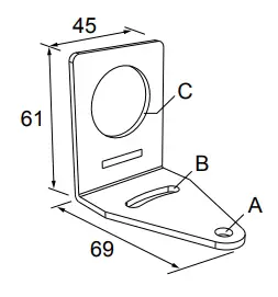
- Right-angle bracket with curved slot for versatile orientation
- Clearance for M6 (¼ in) hardware
- Mounting hole for 30 mm sensor
- 12-ga. stainless steel
Hole center spacing: A to B=40
Hole size: A=ø 6.3, B= 27.1 x 6.3, C=ø 30.5
SMBAMS30P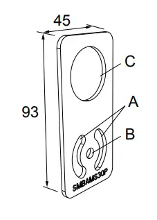
- Flat SMBAMS series bracket
- 30 mm hole for mounting sensors
- Articulation slots for 90°+rotation
- 12-ga. 300 series stainless steel
Hole center spacing: A=26.0, A to B=13.0
Hole size: A=26.8 x 7.0, B=ø 6.5, C=ø 31.0
LMBE12RA35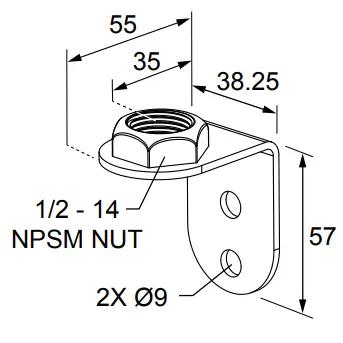
- Direct mounting of stand-off pipe, with common bracket type
- Zinc-plated steel
- 1/2-14 NPSM nut
- Mounting distance from the wall to the
center of the 1/2-14 NPSM nut is 35 mm
Hole center spacing: 20.0
SMB30MM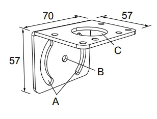
- 12-ga. stainless steel bracket with curved mounting slots for versatile orientation
- Clearance for M6 (¼ in) hardware
- Mounting hole for 30 mm sensor
Hole center spacing: A = 51, A to B = 25.4
Hole size: A = 42.6 x 7, B = ø 6.4, C = ø 30.1
SSA-MBK-EEC1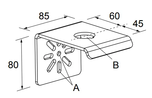
- Single 30 mm hole
- 8 gauge steel, black finish (powder coat)
- Front surface for customer applied labels
Hole size: A = ø 7 , B = ø 30
LMBE12RA45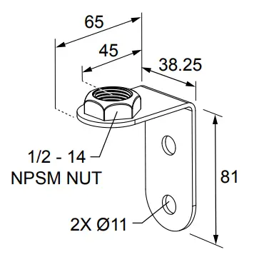
- Direct mounting of stand-off pipe, with common bracket type
- Zinc-plated steel
- 1/2-14 NPSM nut
- Mounting distance from the wall to the center of the 1/2-14 NPSM nut is 45 mm
Hole center spacing: 35.0
Elevated Mount System
| Model | Features | Components | ||
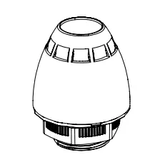
| SA-M30 – Black Polycarbonate |
|  | ||
| SA-M30C – Gray Polycarbonate | ||||
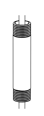
| Polished 304 Stainless Steel | Black Anodized Aluminum | Clear Anodized Aluminum |
| 
|
| SOP-E12-150SS 150 mm (6 in) long | SOP-E12-150A 150 mm (6 in) long | SOP-E12-150AC 150 mm (6 in) long | ||
| SOP-E12-300SS 300 mm (12 in) long | SOP-E12-300A 300 mm (12 in) long | SOP-E12-300AC 300 mm (12 in) long | ||
| SOP-E12-900SS 900 mm (36 in) long | SOP-E12-900A 900 mm (36 in) long | SOP-E12-900AC 900 mm (36 in) long | ||
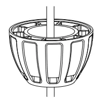
| SA-E12M30 – Black Acetal |
|  | ||
|
SA-E12M30C – White UHMW | ||||
| Pipe Mounting Flange | |||
| Model | Features | Construction | |
| SA-F12 |
| Die-cast zinc base with black paint | 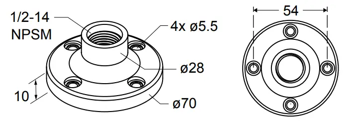 |
| SA-F12-3 |
| Black Polycarbonate | 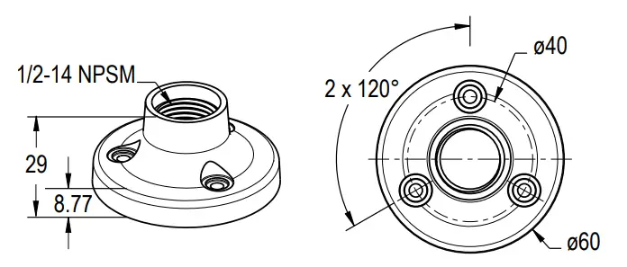 |
| Foldable Mounting Brackets | |||
| Model | Features | Construction | |
| SA-FFB12 |
| Black polycarbonate | 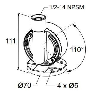 |
| SA-FFB12C | Gray polycarbonate | ||
LMB Sealed Right-Angle Bracket
| Model | Description | Construction | |
| LMB30RA | Direct-Mount Models: Bracket kit with base, 30 mm adapter, set screw, fasteners, O-rings, and gaskets. | Black polycarbonate | 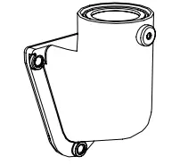
|
| LMB30RAC | Gray polycarbonate | ||
| LMBE12RA | Pipe-Mount Models: Bracket kit with base, ½-14 pipe adapter, set screw, fasteners, O-rings, and gaskets. For use with stand-off pipe (listed and sold separately). | Black polycarbonate | |
| LMBE12RAC | Gray polycarbonate | 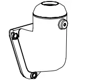 |
Banner Engineering Corp. warrants its products to be free from defects in material and workmanship for one year following the date of shipment. Banner Engineering Corp. will repair or replace, free of charge, any product of its manufacture which, at the time it is returned to the factory, is found to have been defective during the warranty period. This warranty does not cover damage or liability for the misuse, abuse, or improper application or installation of the Banner product.
THIS LIMITED WARRANTY IS EXCLUSIVE AND IN LIEU OF ALL OTHER WARRANTIES WHETHER EXPRESS OR IMPLIED (INCLUDING, WITHOUT LIMITATION, ANY WARRANTY OF MERCHANTABILITY OR FITNESS FOR A PARTICULAR PURPOSE), AND WHETHER ARISING UNDER COURSE OF PERFORMANCE, COURSE OF DEALING, OR TRADE USAGE.
This Warranty is exclusive and limited to repair or, at the discretion of Banner Engineering Corp., replacement. IN NO EVENT SHALL BANNER ENGINEERING CORP. BE LIABLE TO BUYER OR ANY OTHER PERSON OR ENTITY FOR ANY EXTRA COSTS, EXPENSES, LOSSES, LOSS OF PROFITS, OR ANY INCIDENTAL, CONSEQUENTIAL, OR SPECIAL DAMAGES RESULTING FROM ANY PRODUCT DEFECT OR FROM THE USE OR INABILITY TO USE THE PRODUCT, WHETHER ARISING IN CONTRACT OR WARRANTY, STATUTE, TORT, STRICT LIABILITY, NEGLIGENCE, OR OTHERWISE.
Banner Engineering Corp. reserves the right to change, modify or improve the design of the product without assuming any obligations or liabilities relating to any product previously manufactured by Banner Engineering Corp. Any misuse, abuse, or improper application or installation of this product or use of the product for personal protection applications when the product is identified as not intended for such purposes will void the product warranty. Any modifications to this product without prior express approval by Banner Engineering Corp will void the product warranties. All specifications published in this document are subject to change; Banner reserves the right to modify product specifications or update documentation at any time. Specifications and product information in English supersede that which is provided in any other language. For the most recent version of any documentation, refer to:
www.bannerengineering.com.
For patent information, see www.bannerengineering.com/patents.
![]()
© Banner Engineering Corp. All rights reserved
Original Document
182214 Rev. K
2 April 2021
TL70 Modular Tower Light
www.bannerengineering.com – Tel: + 1 888 373 6767
P/N 182214 Rev. K


