
![]() CAT M1 Telematics Generic Installation Kit
CAT M1 Telematics Generic Installation Kit
Instruction Manual
INSTALLATION INSTRUCTIONS
| INSTALLATION GUIDE | GDIEG-01229 |
| KIT PART NUMBER | 96030277 |
| DESCRIPTION | DIRECTED TELEMATICS GENERIC CAT M1 INSTALLATION KIT |
| TO SUIT VEHICLE(S) | |
| APPROX TIME | 30 MINUTES |
| NOTE: CAREFULLY READ AND UNDERSTAND THIS DOCUMENT BEFORE COMMENCING INSTALLATION. WARNING: TAKE CARE TO ENSURE THE VEHICLE IS NOT DAMAGED DURING INSTALLATION. | |
KIT CONTENTS
| NOTE: REMOVE CONTENTS FROM CARTON AND VERIFY ALL PARTS ARE PRESENT. | ||
| DESCRIPTION | PART NUMBER | QUANTITY |
| TELEMATICS MODULE | 8400-13001-00 | 1 |
| BASIC TELEMATICS HARNESS | HDIR215 | 1 |
| GPS ANTENNA 1M | GPSANT02-1000 | 1 |
| 3M VELCRO STRIP | 92034001 | 2 |
TOOLS REQUIRED
PLASTIC TRIM REMOVAL TOOLS
METRIC SOCKET SET
FLAT AND PHILLIPS SCREWDRIVERS
WIRE CRIMPERS AND CRIMPS
SIDE CUTTERS
CABLE TIES
ELECTRIC TAPE
STEP 1
Adhere 3M Velcro tape at the bottom of the telematics module.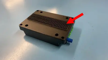 STEP 2
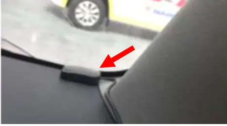
The module has an GSM antenna inside. Adhere the module inside the dashboard most suitable locations for module placement are away from metal that may cause interference.
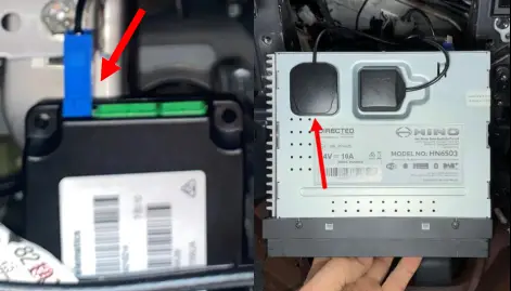
STEP 3
Connect the GPS antenna to the module via the blue Fakra connector and place magnetic antenna of metal surface with clear view of the sky.
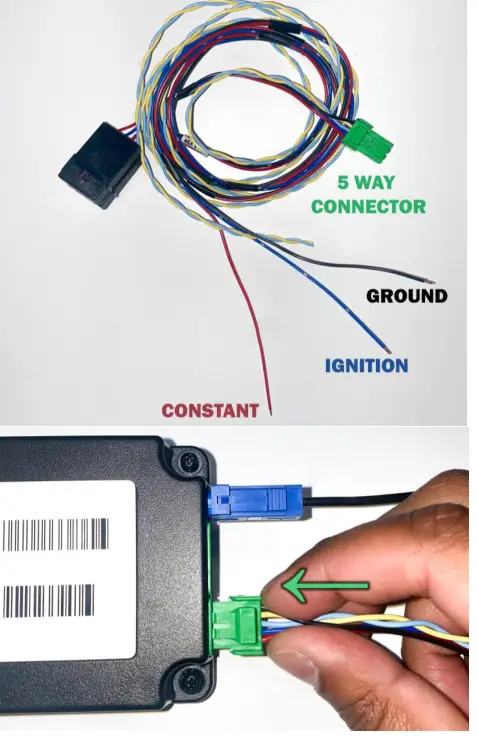
STEP 4
Wire the telematics harness to ground (Black), ignition (Blue) and constant battery power (Red). And connect the 5-way green connector to the telematics module.
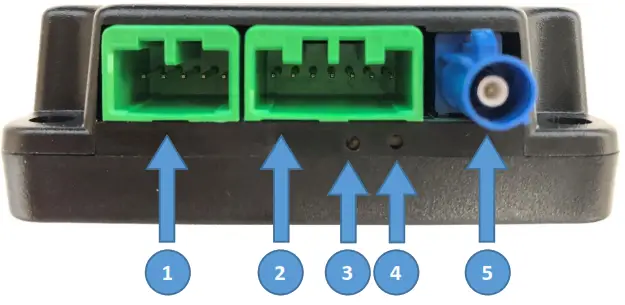
TELEMATICS MODULE INFORMATION
Interface Descriptions
- Telematics
- Auxiliary
- Status LED
- Reset Button
- GPS
Power Specifications
Operating Voltage: 8 – 32 Volts DC
Max Power Consumption: 8W
Status LED Information
| Mode of Operation | Ignition State | Condition | LED Status |
| Normal | OFF | No Data Transmission | OFF |
| OFF | Data Transmission | Green flashing coinciding with data transmission | |
| ON | No Data Transmission | Solid Green | |
| ON | Data Transmission | Green flashing coinciding with data transmission | |
| Fault | ON | Not Receiving Constant Power/Ground/Ignition | OFF |
| ON | Internal Module Fault | Solid Red | |
| ON | Communications Error | Red LED flashing 1 time then off and repeating | |
| ON | GPS Error | Red LED flashing 2 times then off and repeating | |
| ON | CAN Error | Red LED flashing 3 times then off and repeating |
This device complies with part 15 of the FCC Rules. Operation is subject to the following two conditions:
- this device may not cause harmful interference, and
- this device must accept any interference received, including interference that may cause undesired operation.
Any changes or modifications not expressly approved by the party responsible for compliance could void the user’s authority to operate the equipment.
NOTE: This equipment has been tested and found to comply with the limits for a Class B digital device, pursuant to Part 15 of the FCC Rules. These limits are designed to provide reasonable protection against harmful interference in a residential installation. This equipment generates, uses and can radiate radio frequency energy and, if not installed and used in accordance with the instructions, may cause harmful interference to radio communications. However, there is no guarantee that interference will not occur in a particular installation.
If this equipment does cause harmful interference to radio or television reception,which can be determined by turning the equipment off and on, the user is encouraged to try to correct the interference by one or more of the following measures:
- Reorient or relocate the receiving antenna.
- Increase the separation between the equipment and receiver.
- Connect the equipment into an outlet on a circuit different from that to which the receiver is connected.
- Consult the dealer or an experienced radio/TV technician for help.
To maintain compliance with FCC’s RF Exposure guidelines, This equipment should be installed and operated with minimum distance between 20cm the radiator your body: Use only the supplied antenna.
![]() Copyright Directed
Copyright Directed
GDIEG-01229 V1.0 January 22


