Continental G12N410M1 GM OnStar Gen 12 Telematics Control Unit User Manual
Scope of Document
The aim of this document is to provide a short overview on the Telematics Control Unit (TCP) of model G12N410G1 and G12N410M1 and to describe the TCP.
General Product Information
Product type
Telematics Control Unit (TCP)
Manufacturer, Applicant
Continental Automotive GmbH
Siemensstrasse 12
93055 Regensburg
Germany
Brand/Trademark:
Continental
Factory/Manufacturing Location:
Continental Automotive Maquila Mexico, S. de R.L. de C.V.
Carretera Panamericana Sur No, Ext. 114+354 No. Int. 9
Colonia: Parque Industrial Finsa Aguascalientes C.P. 20393
Country of origin:
Mexico
System Overview
Short Description of the TCAM
The product described herein is a Telematics control unit (TCP) for the GM’s GEN12 ONSTAR (Telematics and Connectivity Platform) program. It consists of integrated telematics transceivers for different wireless services, as well as several interfaces to the vehicle. ONSTAR is providing various connectivity services.
North America (NA) Variants
| TCP Variant | TCP Model number | NAD Model Number |
| TCP NA | G12N410G1 | FE4NA0210 |
| TCP NA | G12N410M1 | FE4NA0210 |
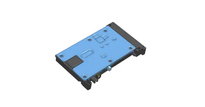
Mechanical design
Pictures of the housing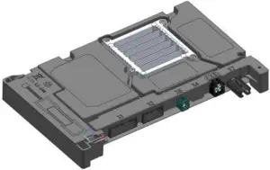
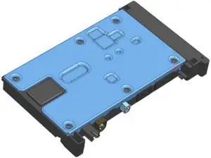
Description of the TCP
Product features
The model main parts are:
- NAD with 3G/4G/LTE and GNSS
- External and internal antennas
- Voice and Data
- Glonass, Beidou, Galileo, GPS
- 2×2 DL-MIMO for 4G
- internal embedded Sim-IC
- Audio subsystem includes analog microphone input and speaker output
- Digital audio interfaces including CODEC and audio PA (Power Amplifier)
- Service calls
- Emergency calls
- Internal Backup Battery (BUB)
- High precision GNSS L1/L5
External interfaces:
- Main power supply
- Primary LTE antennas
- GPS Input
- Three button key pad
- LED control
- External microphone (MIC+/-) input/output
- External backup speaker (SPK+/-) output
- CAN
- Ethernet 100BaseT1 or 1000BaseT1
- Debug interfaces (USB, UART)
Ethernet:
| Model number | Speed |
| G12N410G1 G12N410M1 | 1 GB 100 MB |
Wireless services:
- 3G/WCDMA
- 4G/LTE
- VoLTE
- Voice/Assistance Calls
- Emergency Calls
- Assistance Calls
- Calls are only possible to some fixed phone numbers
- Global Positioning and Navigation: GPS, GNSS, Beidou, Glonass
- Data Services
TCP external Antennas:
- Cell ANT1: 3G/LTE1 (outside verhicle), primary external
- Cell ANT2: LTE2 (Rx LTE only, outside vehicle), secundary external
- GNSS patch (outside verhicle)
- XM patch (outside vehicle)
TCP internal Antennas:
- Cell/Backup ANT3, internal ANT1: 3G/4G/LTE1 (inside vehicle), primary internal
- Cell/Backup ANT4, internal ANT2: 4G/LTE2 (Rx LTE only, inside vehicle), secondary Internal
Connectors
The GM GEN12 TCP has 6 types (fully featured) of connectors (from left to right):
- X1: 20-Pin Main Signal Connector
- X2: 12-Pin Audio and 100BASET1
- X6: Single RF: C-V2X-2
- X3: Quad RF (Cellular PRIMARY, DRX0/GNSS, C-V2X-1)
- X7: 1000BASET1
These variants do not support V2X.
X1 20-Pin Main Connector Pin Out
| Pin | Signal | Pin | Signal | Pin | Signal |
| 1 | VBATT | 8 | CAN_L (IN) | 15 | |
| 2 | VBATT | 9 | GND | 16 | |
| 3 | 10V_REF | 10 | GND | 17 | |
| 4 | Keypad_IN | 11 | 18 | GND | |
| 5 | Green_LED | 12 | 19 | CAN_H (OUT) | |
| 6 | Red_LED | 13 | 20 | CAN_L (OUT) | |
| 7 | CAN_H (IN) | 14 | *Continental Debug Signals | ||
X2 12-Pin Audio and 100BASET1 Connector Pin Out
| Pin | Signal | Pin | Signal | |
| 1 | SPKR_P | 7 | MIC_OUT_N | |
| 2 | SPKR_N | 8 | MIC_OUT_P | |
| 3 | 100BT1_M | 9 | MIC_OUT_N | |
| 4 | 100BT1_P | 10 | MIC Shield | |
| 5 | GND | 11 | GND | |
| 6 | MIC_OUT_P | 12 | GND |
X3 Quad RF Connector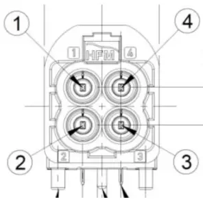
| Pin | Signal |
| 1 | GNSS/DRX0 |
| 2 | V2X_1 |
| 3 | DRX0 |
| 4 | Primary LTE |
X6 Single RF Connector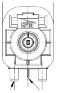
| Pin | Signal |
| 1 | V2X_2 |
X7 1000BASET1 Connector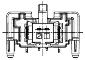
| Pi | Signal |
| 1 | 1000BASET1+ |
| 2 | 1000BASET1- |
Audio Subsystem
The TCU audio system will provide a hands-free user interface for emergency calls and call center concierge/personal calling within the vehicular environment.
The audio system provides the following
- Microphone front end input
- Amplified speaker driver (class D amplifier)
Keypad Subsystem
The keypad subsystem will provide an interface between the user and the TCU for emergency calls and call center concierge/personal calling within the vehicular environment.
The keypad includes the following interfaces:
- Three button interfaces
- Phone Button
- Accept an incoming phone call
- End a phone call
- Initiate OnStar Screen on the infotainment unit
- OnStar Button
- Initiate an OnStar phone call to the Backoffice
- Emergency Button
- Initiate an Emergency phone call to the Backoffice
- Phone Button
- Two color indicator LED’s
- Green
- Red
Technical data
Operating temperature Range
-40°C to 90°C
Supply Voltage
Nominal.: 12 V dc
Supply Voltage Range: 8 V to 16 V dc
Supply current consumption
Typical standby current: 250mA (at 12 V)
Typical active current consumption: 350mA (at 12 V)
Maximum active current consumption: 600mA dc (at 12 V)
Power Consumption
Typical power consumption: 5.5W
(cellular, GNSS active)
Wireless services
- 3G/WCDMA:
Wireless service: 3G/UMTS Frequency bands / range:
Band II (B2: 1900 UMTS): 1850-1910 / 1930-1990 MHz, Band IV (B4: 1700 UMTS): 1710-1755 / 2110-2155 MHz,
Band V (B5: 850 UMTS): 824-849 / 869-894 MHz
Electrical output power: +23.0 dBm (+/- 1dB) - 4G/LTE:
Wireless service: 4G/LTE Frequency bands / range:
Band 2 (1900 LTE): 1850-1910 / 1930-1990 MHz, Band 4 (1700 LTE): 1710-1755 / 2110-2155 MHz,
Band 5 (850 LTE): 824-849 / 869-894 MHz,
Band 12 (700 LTE): 698-716 / 728-746 MHz,
Band 13 (750 LTE): 777-787 / 746-756 MHz,
Band 14 (700 LTE): 788-798 / 758-768 MHz,
Band 28a (700 LTE): 703-718 / 758-773 MHz,
Band 28b (700 LTE): 718-748 / 773-803 MHz, Band 29Rx (700 LTE): – / 717-728 MHz,
Band 30Rx (2300 LTE): 2305-2317 / 2305-2360 MHz,
Band 66 (1700 LTE): 1710-1780 / 2110-2200 MHz
Electrical output power: +23.0 dBm (+/- 1dB) - GNSS receiver:
Wireless service: GNSS Receiver Frequency bands / range: L1/L5
Label Information
USA/Canada
Model: G12N410G1 or G12N410M1
Contains FCC ID: LHJ-FE4NA0210
Contains IC: 2807E-FE4NA0210
Owner Manual Statements
Owner manual USA/Canada
Continental
Model: G12N410G1 or G12N410M1
Contains FCC ID: LHJ-FE4NA0210
Contains IC: 2807E-FE4NA0210
This device complies with Part 15 of the FCC Rules and Industry Canada licence-exempt RSS standard(s). Operation is subject to the following two conditions:
- this device may not cause interference, and
- this device must accept any interference, including interference that may cause undesired operation of the device.
This device complies with FCC/ISED radiation exposure limits set forth for an uncontrolled environment and meets the FCC radio frequency (RF) Exposure Guidelines and RSS‐102 of the ISED radio frequency (RF) Exposure rules. This transmitter must not be co-located or operating in conjunction with any other antenna or transmitter. The antenna should be installed and operated with minimum distance of 20 cm between the radiator and your body.
FCC Class B digital device notice
This equipment has been tested and found to comply with the limits for a Class B digital
device, pursuant to part 15 of the FCC Rules. These limits are designed to provide reasonable protection against harmful interference in a residential installation. This equipment generates, uses and can radiate radio frequency energy and, if not installed and used in accordance with the instructions, may cause harmful interference to radio communications. However, there is no guarantee that interference will not occur in a particular installation. If this equipment does cause harmful interference to radio or television reception, which can be determined by turning the equipment off and on, the user is encouraged to try to correct the interference by one or more of the following measures:
- Reorient or relocate the receiving antenna.
- Increase the separation between the equipment and receiver.
- Connect the equipment into an outlet on a circuit different from that to which the receiver is connected.
- Consult the dealer or an experienced radio/TV technician for help.
Continental Automotive GmbH has not approved any changes or modifications to this device by the user. Any changes or modifications could void the user’s authority to operate the equipment.
CAN ICES-3 (B) / NMB-3 (B)
This Class B digital apparatus complies with Canadian ICES-003.