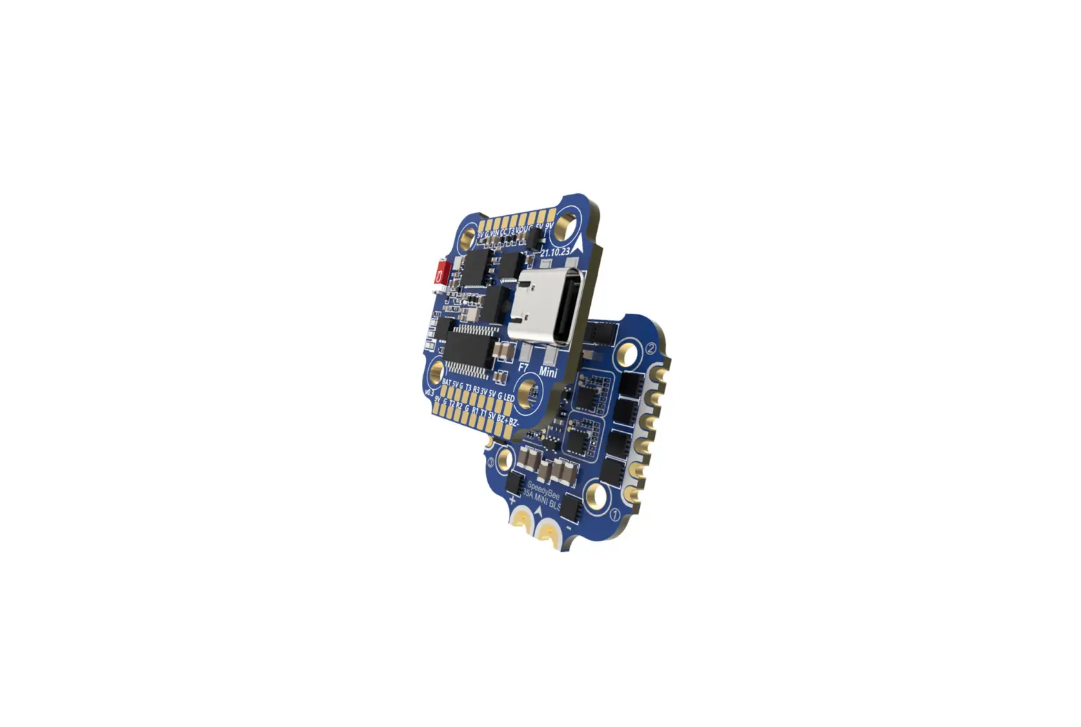
SpeedyBee F7 35A BLS Mini Flight Controller Stack
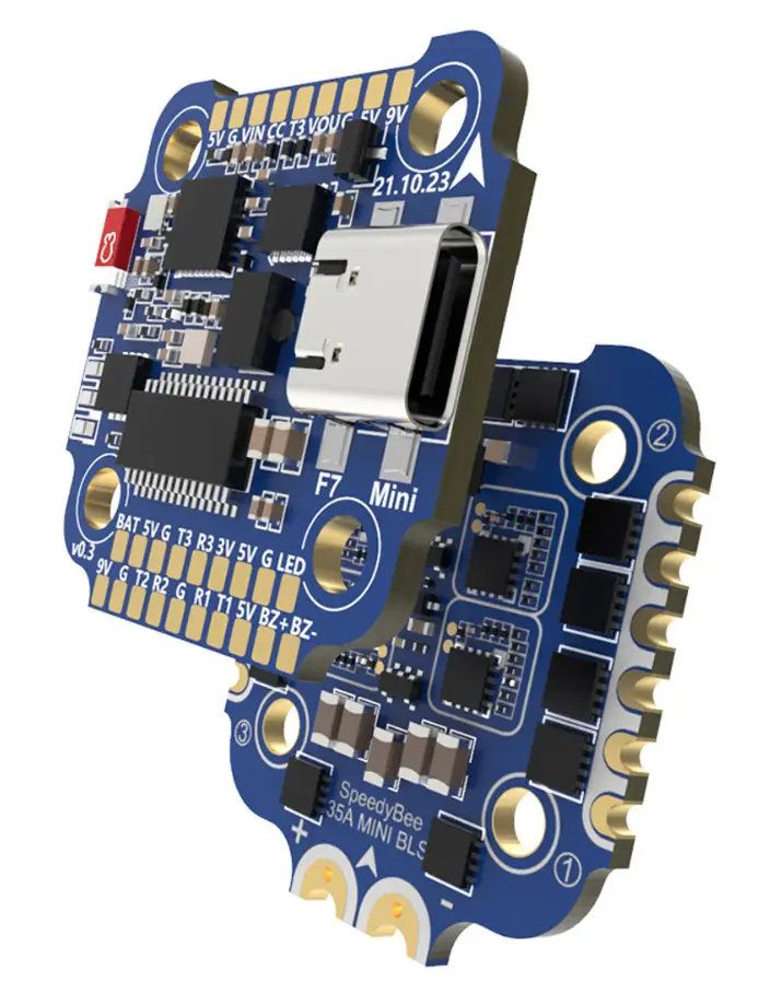
Overview
Specs Overview
| Product Name | SpeedyBee F7 35A BLS Mini Stack |
| Flight Controller | SpeedyBee F7 Mini |
| ESC | SpeedyBee 35A BLS Mini 4-in-1 ESC |
| Bluetooth | Supported. For FC & ESC parameter setting |
| Wireless FC Firmware Flashing | Not supported |
| Wireless Blackbox Download | Not supported |
| Power Inpu t | 3-6S LiPo |
| Mounting | 20 x 20mm ø3.5mm hole size, Compatible with M2 and M3 screws/Silicone grommets |
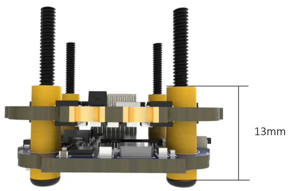
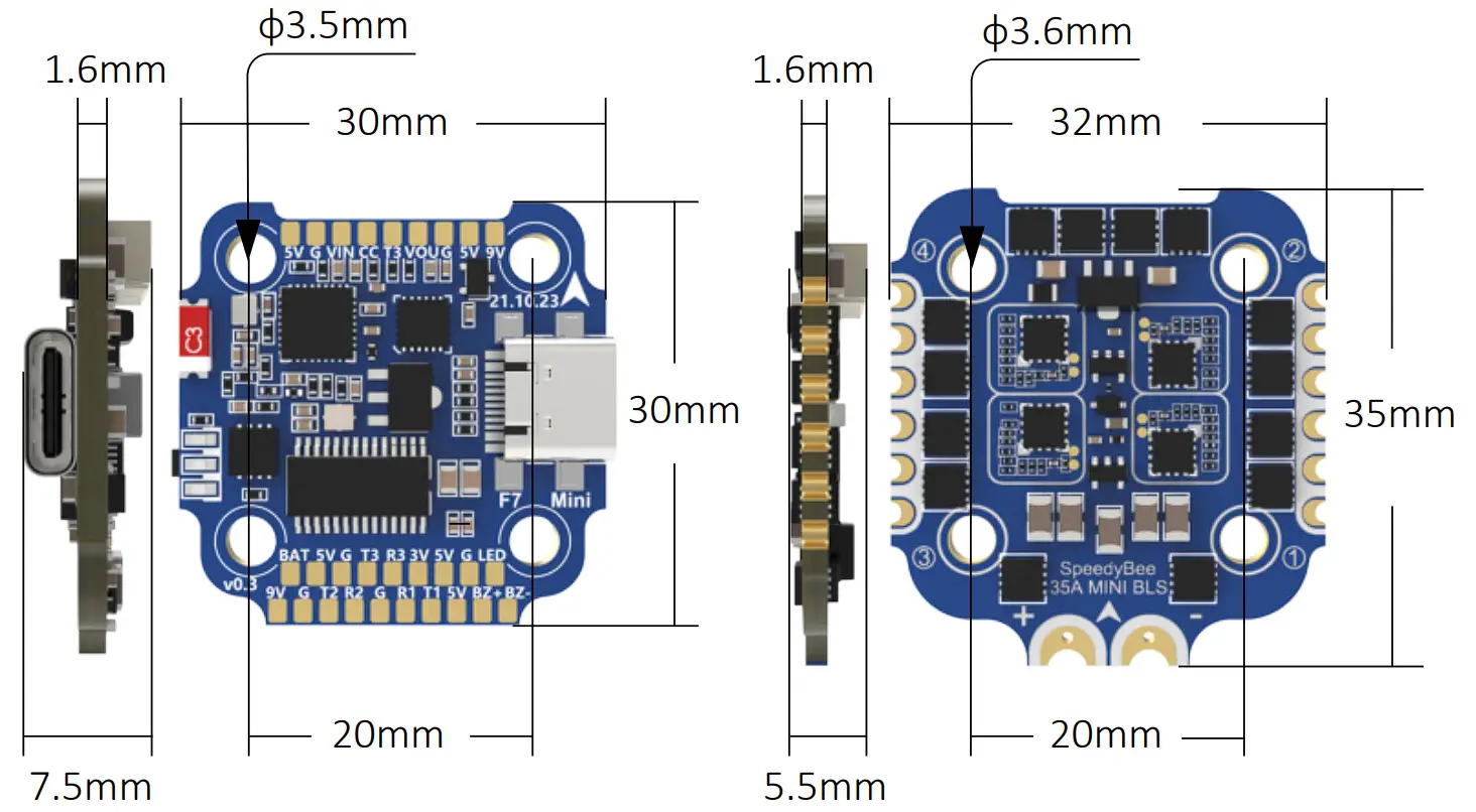
| Dimension | 32mm(L) x 35mm(W) x 13mm(H) |
| Weight | 12.7g |
Dimensions
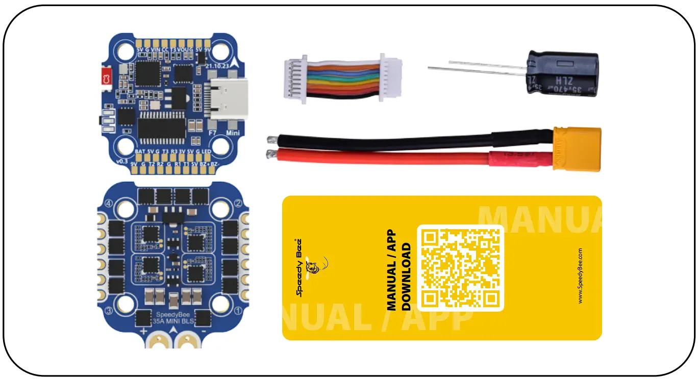
Package
- SpeedyBee F7 Mini Flight Controller x 1
- SpeedyBee 35A BLHeli_S Mini 4-in-1 ESC x 1
- Manual & App Download Card x 1
- XT30 Power Cable(Length: 7cm) x 1
- Spin JST cable(For FC & ESC Connection) x 1
- 35V 470uF Capacitor x 1
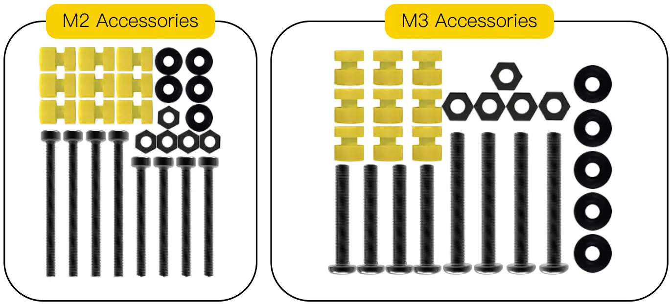
- M2 Accessories
- M2(Diameter) * 20mm(Length) Screw x 4
- M2(Diameter) * 25mm(Length) Screw x 4
- M2(Hole Diameter) * 6.6mm(Height) Anti-vibration Silicone Grommets x 9
- M2 Silicone O-Ring x 5
- M2 Nylon Hex Nut x 5
- M3 Accessories
- M3(Diameter) * 20mm(Length) Screw x 4
- M3(Diameter) * 25mm(Length) Screw x 4
- M3(Hole Diameter) * 6.6mm(Height) Anti-vibration Silicone Grommets x 9
- M3 Silicone O-Ring x 5
- M3 Nylon Hex Nut x 5
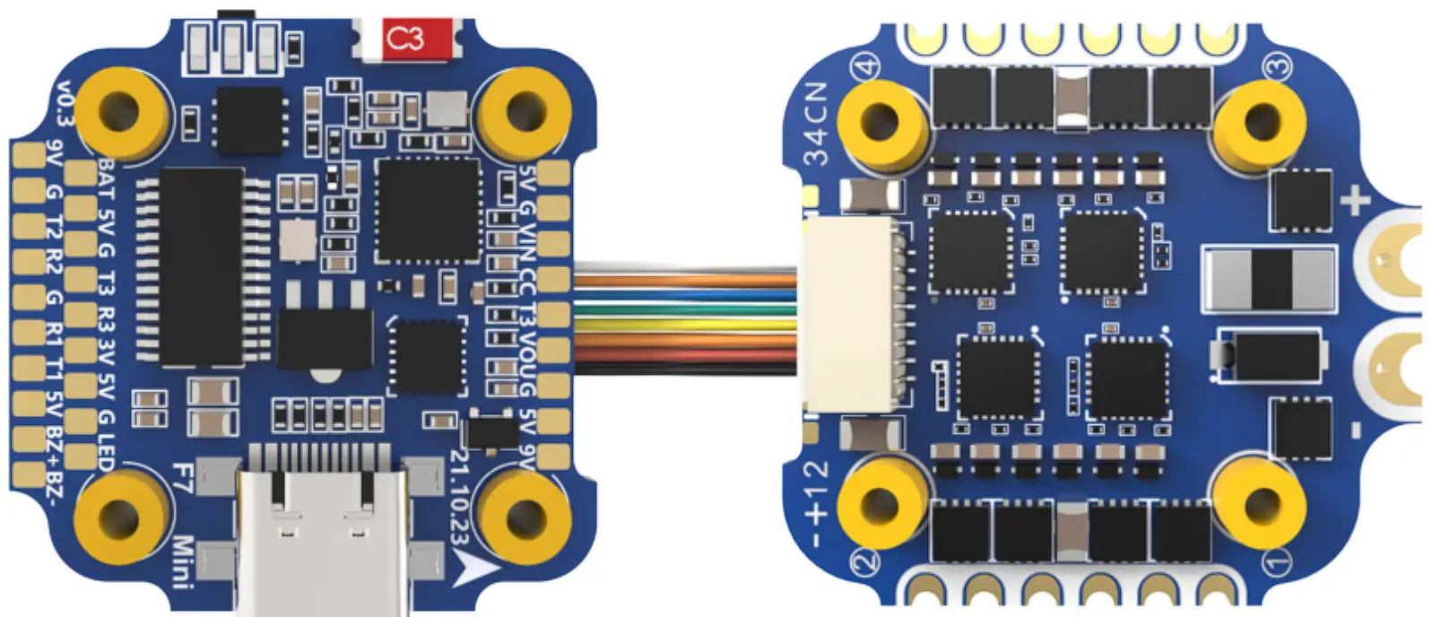
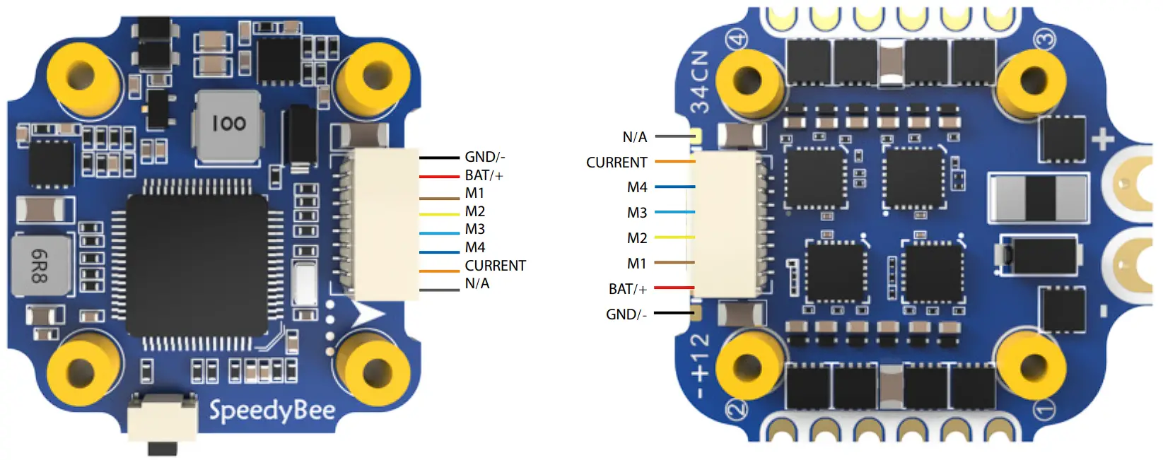
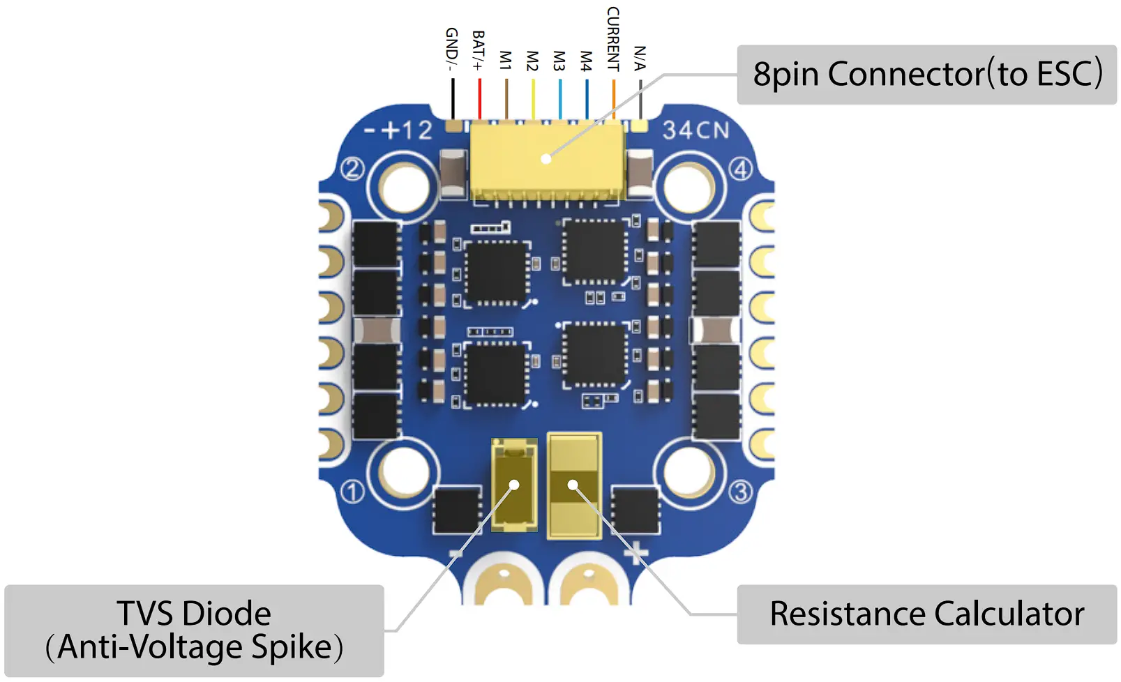
FC & ESC Connection
Use any end of the 8-pin JST cable to connect the FC to the ESC.
SpeedyBee F7 Mini Flight Controller
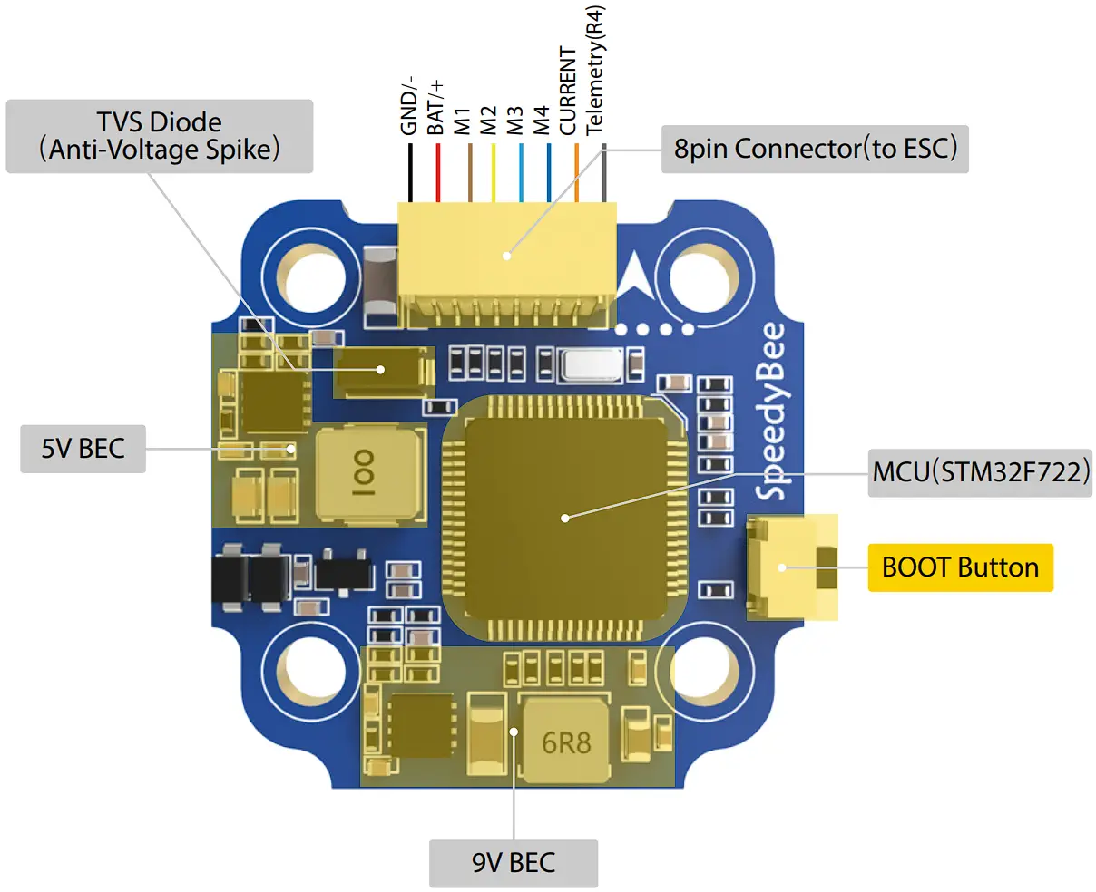
Layout
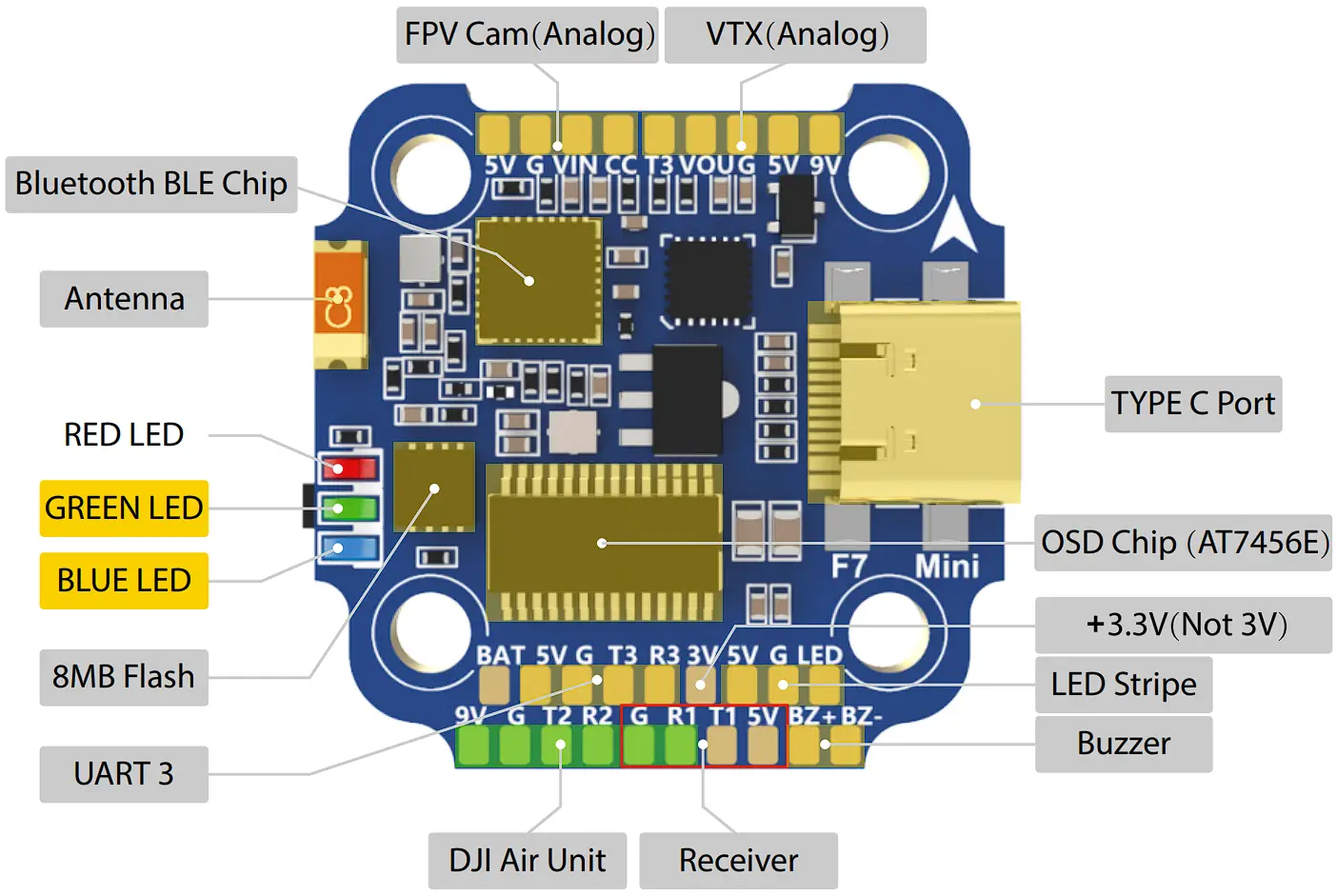
- LED Indicator Definition
 RED LED – Solid Red after powering up. GREEN LED – Blinking Green indicates Bluetooth is open and waiting forconnection; Solid Green indicates Bluetooth is connected. BLUE LED – Flight controller status light which is controlled by the flight controller firmware.
 - BOOT Button
Only if the flight controller gets bricked and can’t power up, please follow these steps to re-flash firmware for it:
① Insert a USB A to TYPE-C cable to your PC.
② Press and hold the BOOT button, insert the USB cable into the flight controller, then release the BOOT button.
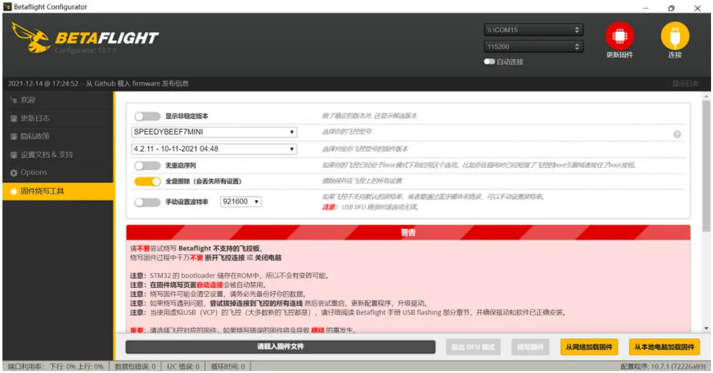
③ Open Betaflight/ Emuflight/lNAV configurator on the PC, go to the ‘Firmware Flashing’ page, choose the target ‘SPEEDYBEEF7MINI’ and flash.
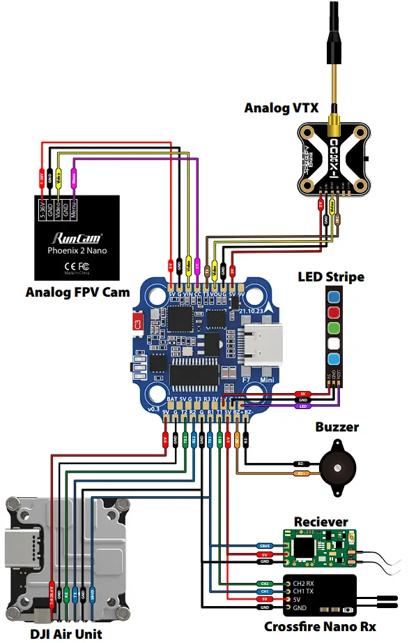
FC’s Peripheral Connection
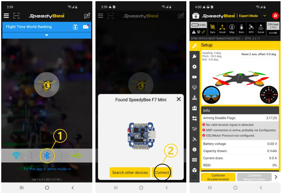
APP
- Get the SpeedyBee App
Search ‘SpeedyBee’ on Google Play or App Store. Or download the Android .apk file on our website: https://www.speedybee.com/download. - Connect the App

FC Firmware Update
- SpeedyBee F7 Mini does not support wireless firmware flashing, so please flash firmware for it on your PC following the steps below:
① Connect the flight controller to the PC with a USB cable
② Open Betafight/Emuflight/lNAV configurator on your PC. Take Betaflight configurator as an example, go to the ‘Firmware Flashing’ page, choose the target ‘SPEEDYBEEF7MINI’ and flash.
Parameters
| MCU | STM32F72 2 |
| IMU(Gyro) | MPU6000 |
| USB Port Type | Type- C |
| Barometer | N/A |
| OSD Chip | AT7456E chip |
| BLE Bluetooth | Supported. Used for Flight Controller configuration |
| Flash FC Firmware Wirelessly | Not supported. Please update firmware for this FC on the PC |
| Download/ Analyze Blackbox | Not supported. Please download and analyze Blackbox data on the PC |
| OJI Air Unit Soldering Pads | Supported |
| Flash(for BlackBox) | 8MB |
| Current Sensor | Supported, Scale=250 Offset=- 500 |
| BetaFlight Camera Control Pad | Yes (CC pad) |
| Power Input | 3S – 6S Lipo |
| 5V Output | 6 groups of SV output, five +5V pads and 1 BZ+ pad( used for Buzzer). The total current load is 2.SA. |
| 9V Output | 2 groups of 9V output , the total current load is 2A. |
| 3.3V Output | Supported. Up to 500mA current load. |
| ESC Signal Pads | M1 – M4 |
| UART | Full UART * 3(UART1, UART2, UART3) |
| ESC Telemetry UART | R4(UART4) |
| 12( | Not supported |
| LED Pad | Used for WS2812 LED |
| Buzzer | BZ+ and BZ- pad used for SV Buzzer |
| BOOT Button | Used to enter DFU mode |
| RSSI Input | Not supported |
| SmartPort | Use any TX pad of UART f or the SmartPort feature. |
| Supported Flight Controller Firm ware | BetaFlight (Default), EMUF light, INAV |
| Firm ware Target Name | SPEEDYBEEF7MINI |
| Mounting | 20 x 20mm, 3.5mm hole diameter |
| Dimension | 30 x 30 x 7.5m m |
| Weight | 5.7g |
SpeedyBee 35A BLS 4-in-1 ESC
Layout
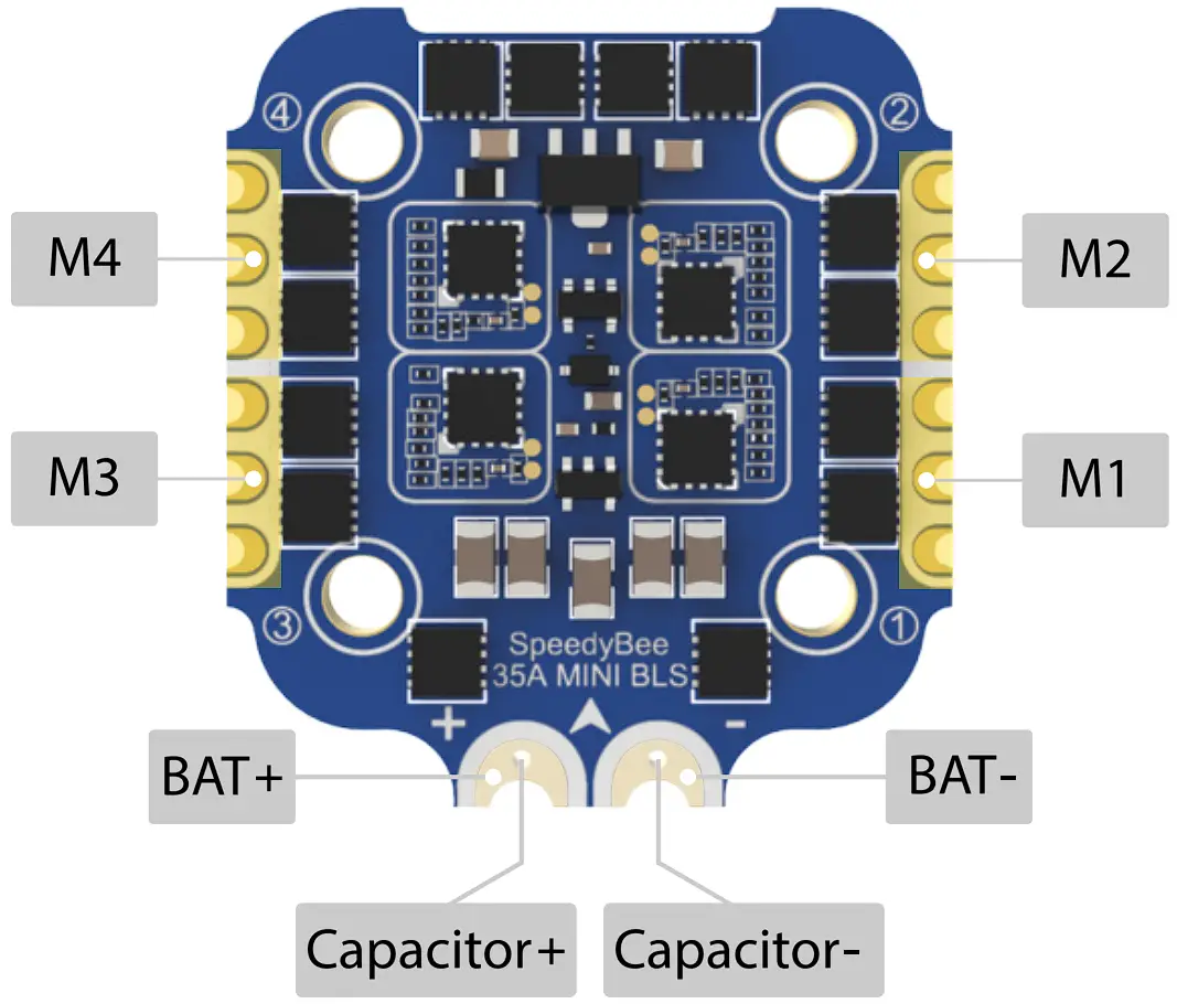
Connection with Motors & Power Cable
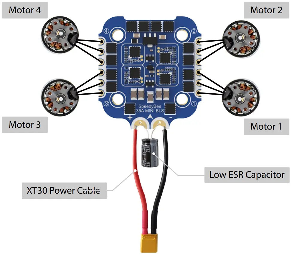
- Note: In order to prevent the stack from being burnt out instantaneous voltage spikes on powering up, it is strongly recommended to use the Low ESR capacitor in the package.
ESC Configuration
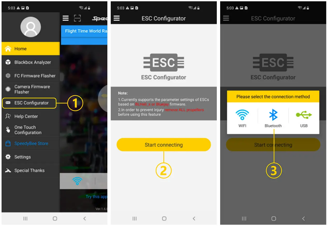
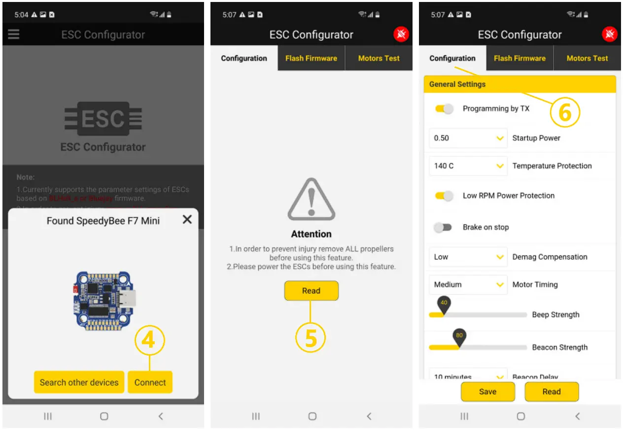
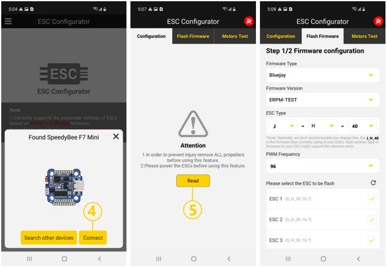
ESC Firmware Update
- You could flash both BLHeli_S and Blue Jay firmware for this ESC via Bluetooth.
Note: ESC Type should be set as ‘J-H-40’.

Parameters
| Firmware | BLHeli_S JH40 |
| Continuous Current | 35A *4 |
| Burst Current | 45A(SS) |
| ESC Protocol | DSHOT300/ 600 |
| Power Input | 3-6S LiPo |
| Power Output | VBAT |
| Current Sensor | Support (Scale=250 Offset=-500) |
| Mounting | 20 x 20mm, 3.6mm hole diameter |
| Dimension | 32(L) * 35(W) * 5.5mm(H) |
| Weight | 7g |