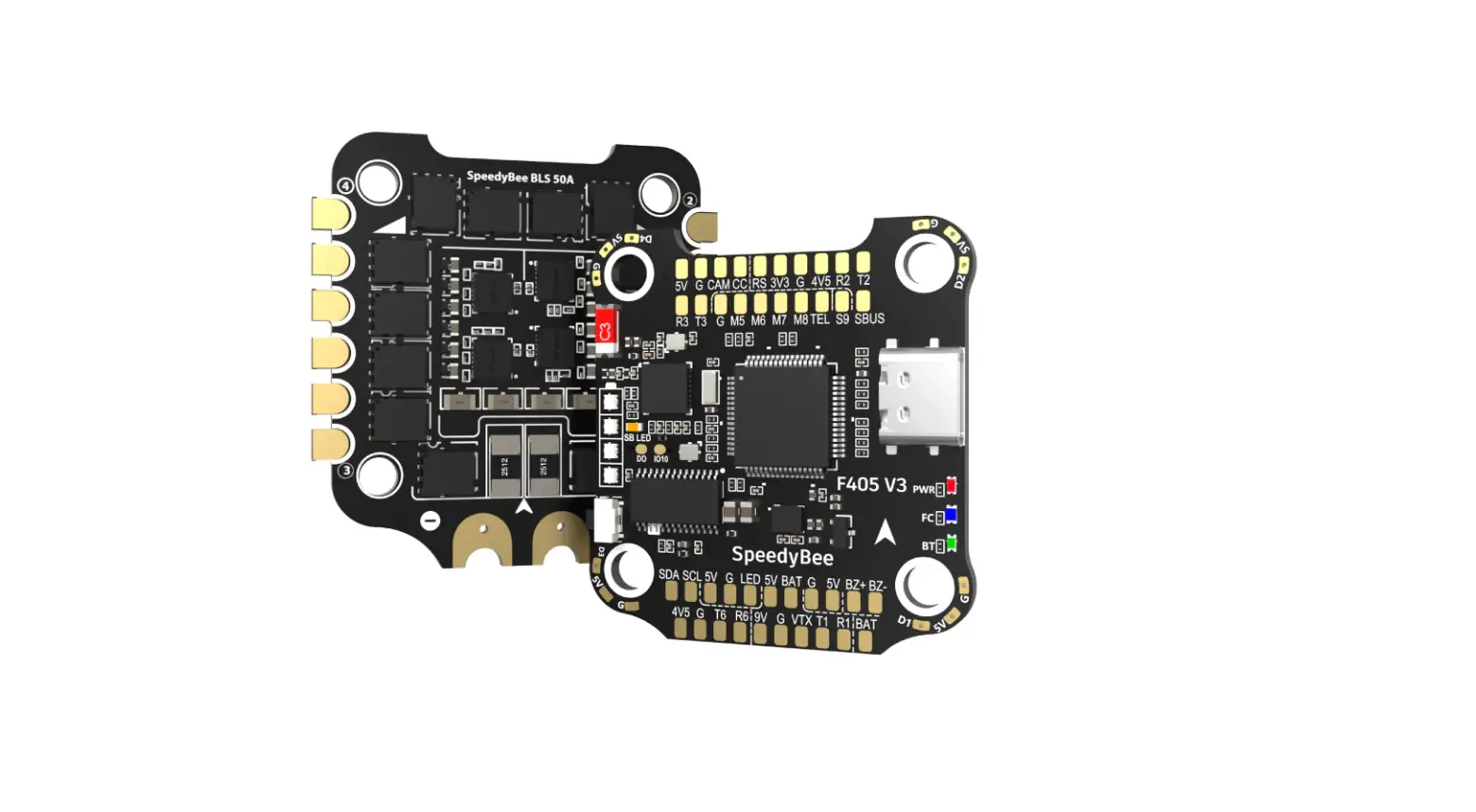
SpeedyBee F405 V3 BLS 50A 30×30 Stack for FPV Drones Instruction Manual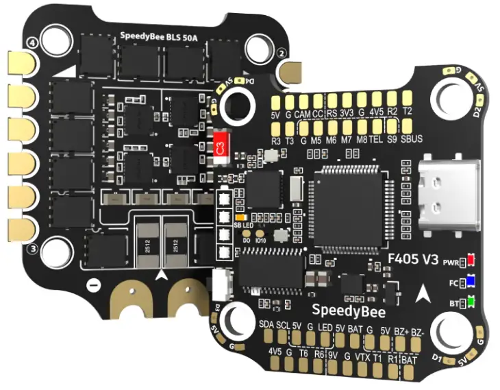
Overview
Specs Overview
| Product Name | SpeedyBee F405 V3 BLS 50A 30×30 Stack |
| Flight Controller | SpeedyBee F405 V3 |
| ESC | SpeedyBee BLS 50A 4-in-1 ESC |
| Bluetooth | Supported. For FC & ESC parameter settings |
| Wireless FC Firmware Flashing | NOT Supported |
| Wireless Black box Downloads & Analysis | NOT Supported |
| Power Input | 3-6S LiPo |
| Mounting | 30.5 x 30.5mm(4mm hole size ) |
| Dimension | 45.6mm(L) x 44mm(W) x 18.3mm(H) |
| Weight | 23.4g |
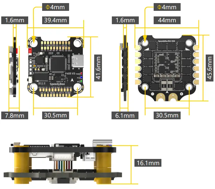
Dimensions
Package
Option 1 – SpeedyBee F405 V3 50A 30×30 Stack
1 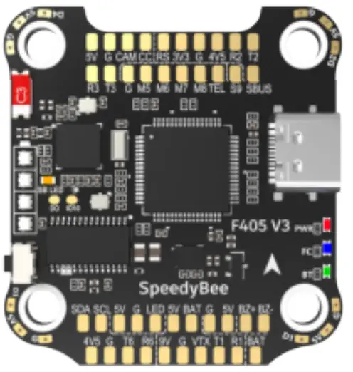 | 3 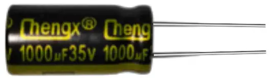 | 9 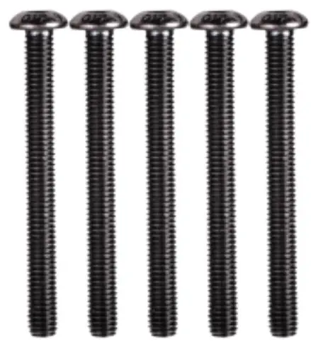 | 11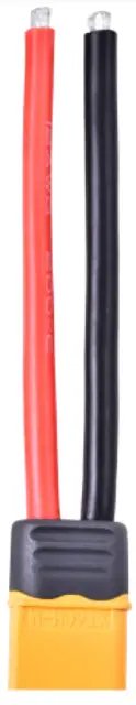 |
4 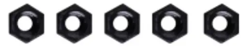 | |||
5  | |||
2 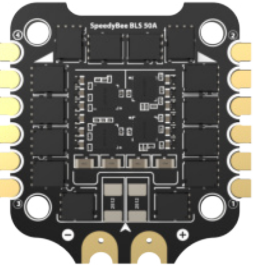 | 6  | 10 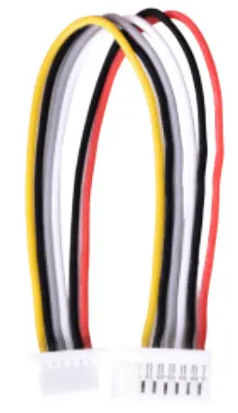 | |
7  | |||
8 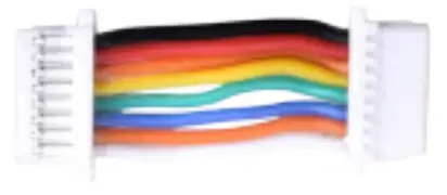 |
- SpeedyBee F405 V3 Flight Controller x 1
- SpeedyBee BLS 50A 4-in-1 ESC x 1
- 35V 1000uF Low ESR Capacitor x 1
- M3 Nylon Nut x 5
- M3 silicone O Ring x 5
- M3*8mm Silicone Grommets(for FC) x 5
- M3*8.1mm Silicone Grommets(for ESC) x 5
- SH 1.0mm 15mm-length 8pin Cable(for FC-ESC connection) x 1
- M3*30mm Iner-hexagon Screws x 5
- DJI 6pin Cable(80mm) x 1
- XT60 Power Cable(70mm) x 1
Option 2 – SpeedyBee F405 V3 Flight Controller
1 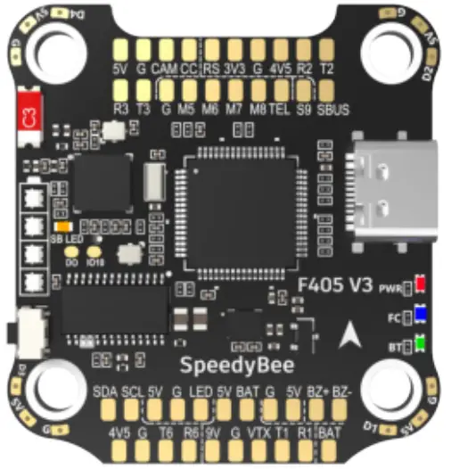 | 2 | 4 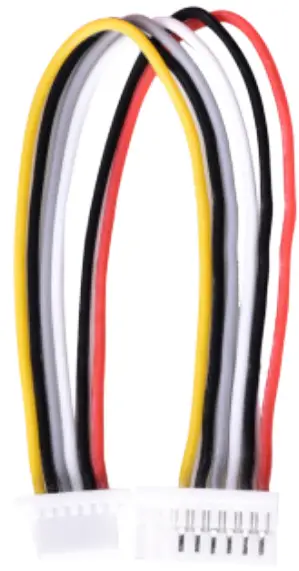 |
3 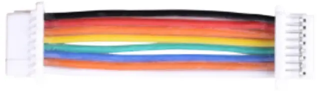 |
- SpeedyBee F405 V3 Flight Controller x 1
- M3*8mm Silicone Grommets(for FC) x 5
- SH 1.0mm 30mm-length 8pin Cable(for FC-ESC connection) x 1
- DJI 6pin Cable(80mm) x 1
Option 3 – SpeedyBee BLS 50A 4-in-1 ESC
1 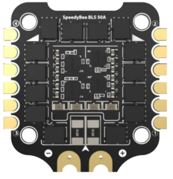 | 2 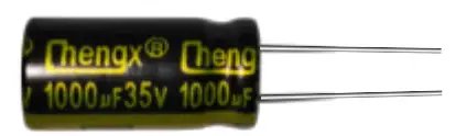 | 5 |
3  | 6  | |
4 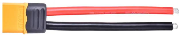 | ||
- SpeedyBee BLS 50A 4-in-1 ESC x 1
- 35V 1000uF Low ESR Capacitor x 1
- M3 silicone O Ring x 5
- XT60 Power Cable(70mm) x 1
- SH 1.0mm 30mm-length 8pin Cable(for FC-ESC connection) x 1
- M3*8.1mm Silicone Grommets(for ESC) x 5
FC & ESC Connection
Use the 8-pin cable in the package to connect the FC and the ESC. Or solder 8 wires directly to the 8 pads on each end.
Method 1 – Using 8-pin cable
Use any end of the 8-pin JST cable to connect the FC to the ESC.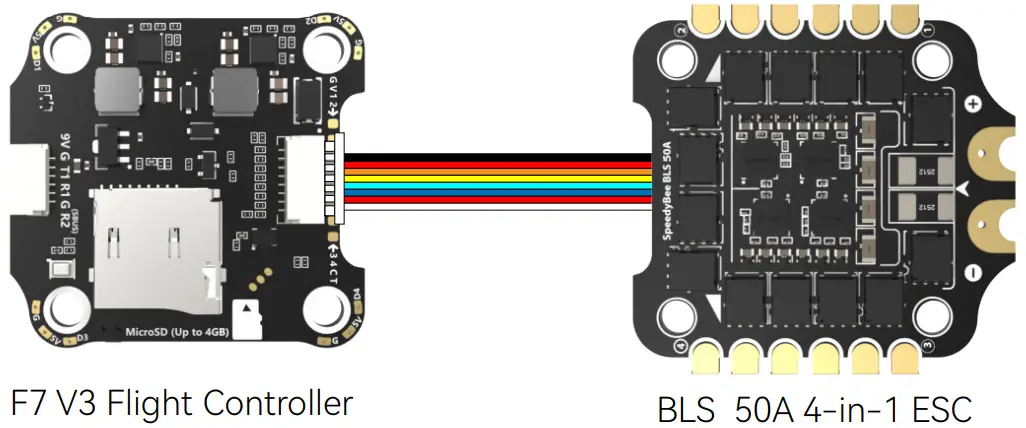
Method 2 – Direct soldering
Solder 8 wires to the 8 pads on each end referring to the pad definition below.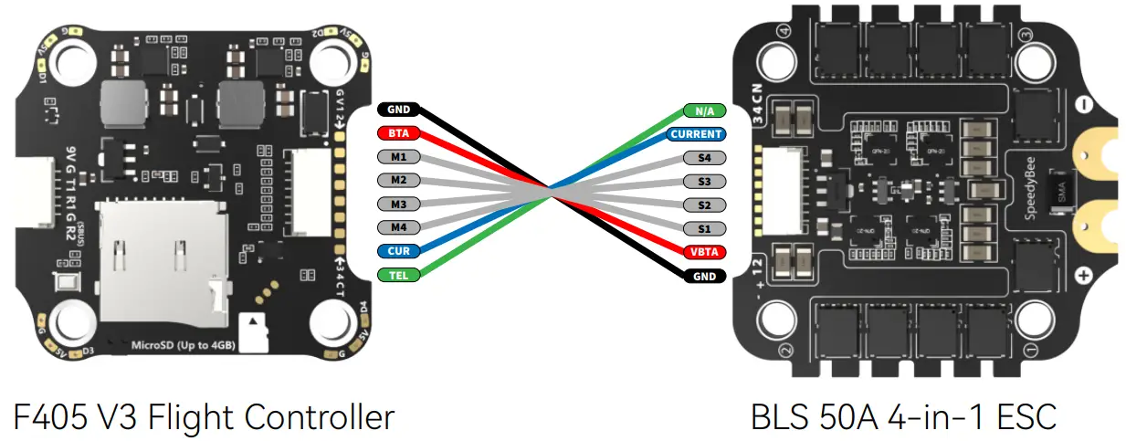
F405 V3 Flight Controller
Layout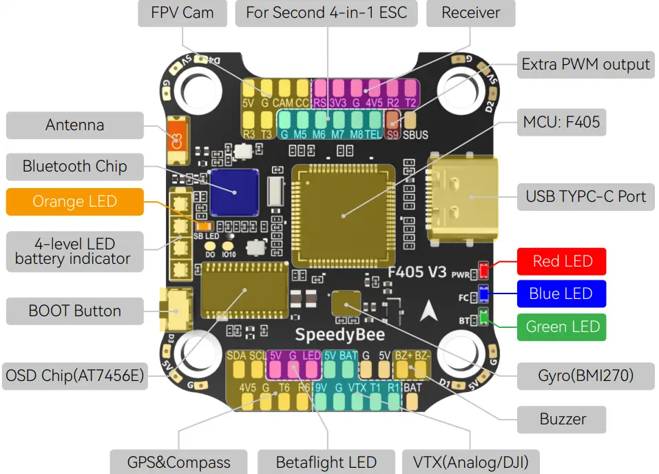
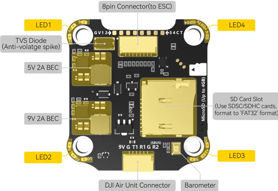
LED Indicator Definition
RED LED – Power Indicator.Solid Red after powering up.
GREEN LED – Bluetooth status light. Solid Green indicates Bluetooth is connected.
BLUE LED – Flight controller status light which is controlled by the flight controller firmware.
Orange LED – LED Control Mode Indicator. It indicates the 4 sets of LED strips connected to LED1-LED4 pads on the corners of the flight controller are controlled by Betaflight
firmware(BF_LED mode) or the Bluetooth chip(SB_LED mode).
Solid Orange :tindicates the 4 x LEDs are in SB_LED mode. In this mode, when the FC is powered on and in standby mode, press the BOOT button to cycle the display modes of the LEDs. You could also change modes in the app wirelessly.
OFF :indicates the 4 x LEDs are controlled by Betaflight firmware.
Long press the button for 3 seconds to switch the control modes between BF_LED mode and SB_LED mode.
[A] Only if the flight controller gets bricked and can’t power up, please follow these steps to re-flash firmware for it:
- Insert a USB A to TYPE-C cable to your PC.
- Press and hold the BOOT button, insert the USB cable into the flight controller, then release the BOOT button.
- Open Betaflight/Emuflight/INAV configurator on the PC, go to the ‘Firmware Flashing’ page, choose the target ‘SPEEDYBEEF405V3’ and flash.
[B]. When the FC is powered on and in standby mode, the BOOT button can be used to controller the LED strips connected to LED1-LED4 pads on the corners. By default, short-press the BOOT button to cycle the LED displaying mode. Long-press the BOOT button to switch between SpeedyBee-LED mode and BF-LED mode. Under BF-LED mode, all the LED1-LED4 strips will be controlled by the Betaflight firmware.
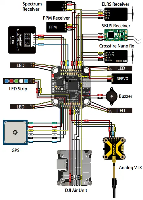
FC’s Peripheral Connection
App & FC Configuration
Get the SpeedyBee App
Search ‘SpeedyBee’ on Google Play or App Store. Or download the Android .apk file on our website: https://www.speedybee.com/download.
FC Configuration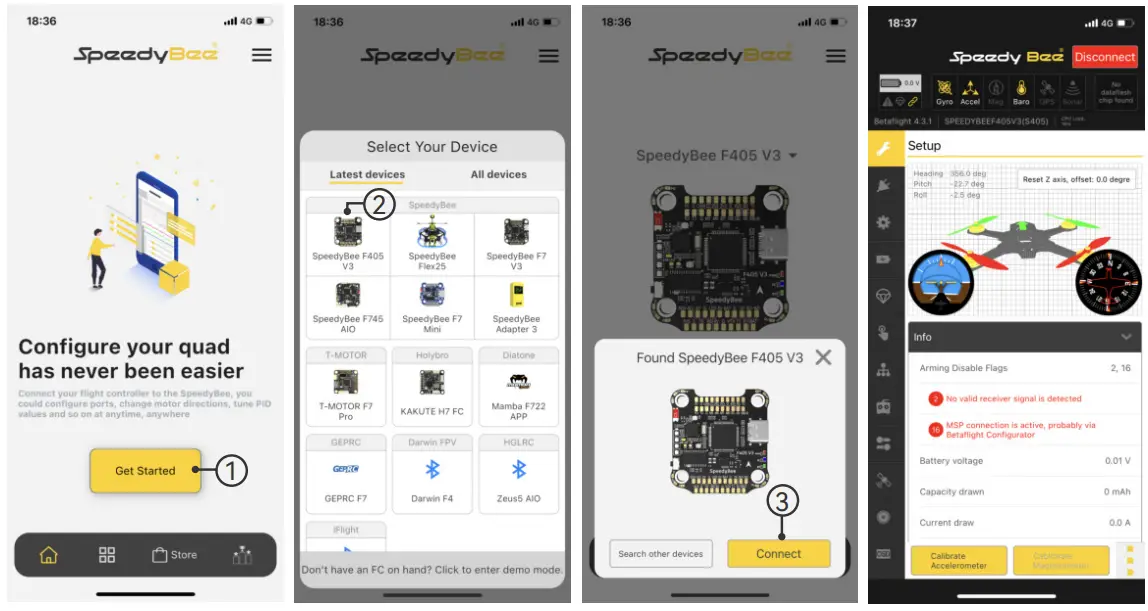
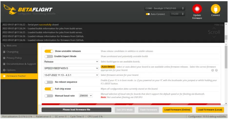
FC Firmware Update
SpeedyBee F405 V3 flight controller does not support wireless firmware flashing,
so please flash firmware for it on your PC following the steps below:
- Connect the flight controller to the PC with a USB cable
- Open Betafight/Emuflight/INAV configurator on your PC. Take Betaflight configurator as an example, go to the ‘Firmware Flashing’ page, choose the target ‘SPEEDYBEEF405V3’ and flash.
Specifications
| Product Name | SpeedyBee F405 V3 30×30 Flight Controller |
| MCU | STM32F405 |
| IMU(Gyro) | BMI270 |
| USB Port Type | Type-C |
| Barometer | Built-in |
| OSD Chip | AT7456E chip |
| BLE Bluetooth | Supported. Used for Flight Controller configuration(MSP should be enabled with Baud rate 115200 on UART 4) |
| DJI Air Unit Connection Way | Two ways supported: 6-pin connector or direct soldering. |
| 6-pin DJI Air Unit Plug | Supported. Completely compatible with DJI O3/RunCam Link/Caddx Vista/ DJI Air Unit V1, no wire is needed to be changed. |
| Blackbox MicroSD Card Slot | Supported. Please use ≤4GB SDSC/SDHC microSD card and should be formatted to FAT16/FAT32 format. Don’t use SDXC cards. Note: Betaflight can only recognize 4GB max. |
| BetaFlight Camera Control Pad | Yes(CC pad on the front side) |
| Current Sensor Input | Supported. For SpeedyBee BLS 50A ESC, please set scale = 386 and Offset = 0. |
| Power Input | 3S – 6S Lipo(Through G, BAT pins/pads from the 8-pin connector or 8-pads on thebottom side) |
| 5V Output | 9 groups of 5V output, four +5V pads and 1 BZ+ pad( used for Buzzer) on front side, and 4x LED 5V pads. The total current load is 2A. |
| 9V Output | 2 groups of 9V output, one +9V pad on front side and other included in a connectoron bottom side. The total current load is 2A. |
| 3.3V Output | Supported. Designed for 3.3V-input receivers. Up to 500mA current load. |
| 4.5V Output | Supported. Designed for receiver and GPS module even when the FC is powered through the USB port. Up to 1A current load. |
| ESC Signal | M1 – M4 on bottom side and M5-M8 on front side. |
| UART | 6 sets(UART1, UART2, UART3, UART4(Dedicated for Bluetooth connection), UART5(Dedicated for ESC telemetry), UART6) |
| ESC Telemetry | UART R5(UART5) |
| I2C | Supported. SDA & SCL pads on front side. Used for magnetometer, sonar, etc. |
| Traditional Betaflight LED Pad | Supported. 5V, G and LED pads on bottom of the front side. Used for WS2812 LEDcontrolled by Betaflight firmware. |
| Buzzer | BZ+ and BZ- pad used for 5V Buzzer |
BOOT Button | Supported.[A]. Press and hold BOOT button and power the FC on at the same time will force theFC to enter DFU mode, this is for firmware flashing when the FC gets bricked.[B]. When the FC is powered on and in standby mode, the BOOT button can be used to controller the LED strips connected to LED1-LED4 connectors on the bottom side. By default, short-press the BOOT button to cycle the LED displaying mode. Long- press the BOOT button to switch between SpeedyBee-LED mode and BF-LED mode. Under BF-LED mode, all the LED1-LED4 strips will be controlled by Betaflight firmware. |
| RSSI Input | Supported. Named as RS on the front side. |
| Smart Port / F.Port | Not supported |
| Supported Flight Controller Firmware | BetaFlight(Default), EMUFlight, INAV |
| Firmware Target Name | SPEEDYBEEF405V3 |
| Mounting | 30.5 x 30.5mm( 4mm hole diameter) |
| Dimension | 41.6(L) x 39.4(W) x 7.8(H)mm |
| Weight | 9.6g |
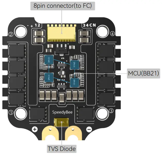
SpeedyBee BLS 50A 4-in-1 ESC
Layout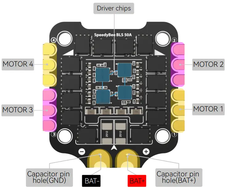
Connection with Motors & Power Cable
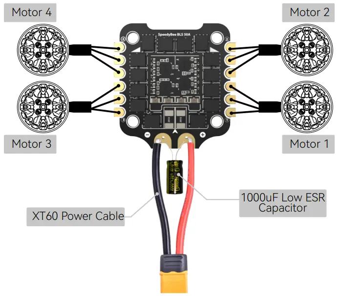
Note: In order to prevent the stack from being burnt out by voltage spikes
on powering up, it is strongly recommended to use the Low ESR capacitor in the package.
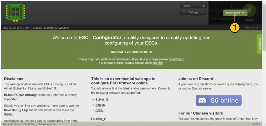
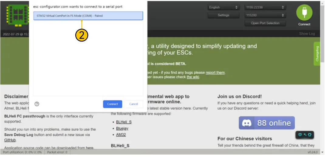
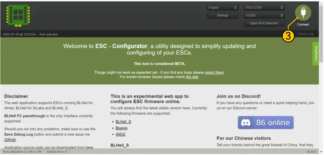
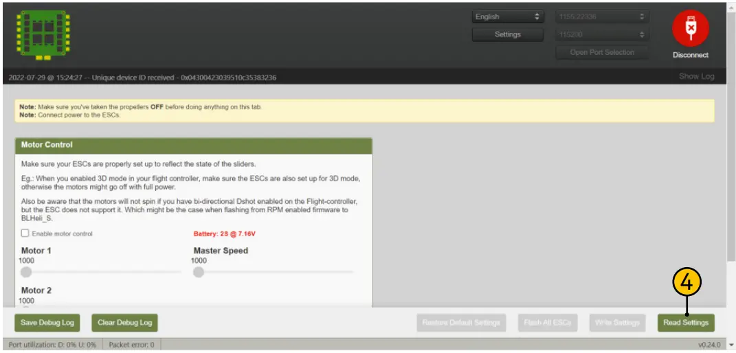
ESC Configuration
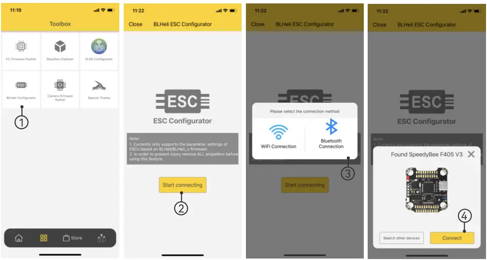
- If you’d like to use a PC configurator, we recommend the ESC Configurator.
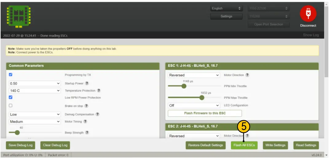
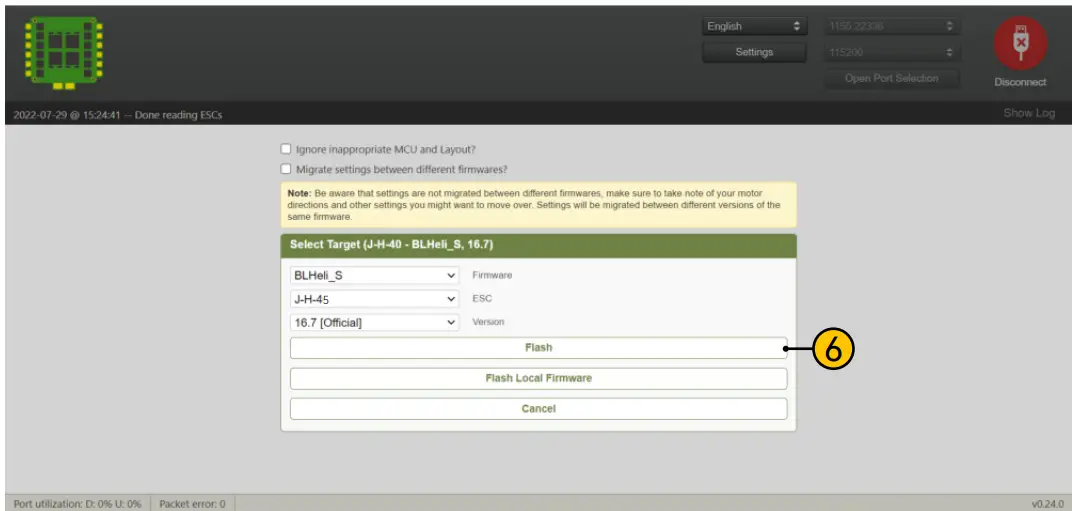
ESC Firmware Update
- You could flash both BLHeli_S and Blue Jay firmware for this ESC.
You need to pulg in the battery to the F405 V3 and then connect a USB
cable between the F405 V3 and your PC. Then flash ESC firmware
(BLHeli_S or Blue Jay) in the following online configurator:
https://esc-configurator.com/
Note: ESC Type should be set as ‘J-H-50


Specifications
| Product Name | SpeedyBee BLS 50A 30×30 4-in-1 ESC |
| Firmware | BLHeli_S JH50 |
| Wireless Configuration | Full Configuration Supported in the SpeedyBee app |
| PC Configurator Download Link | https://esc-configurator.com/ |
| Continuous Current | 50A * 4 |
| Burst Current | 55A(5S) |
| TVS Protective diode | Yes |
| External Capacitor | 1000uF Low ESR Capacitor(In the package) |
| ESC Protocol | DSHOT300/600 |
| Power Input | 3-6S LiPo |
| Power Output | VBAT |
| Current Sensor | Support (Scale=386 Offset=0) |
| Mounting | 30.5 x 30.5mm( 4mm hole diameter) |
| Dimension | 45.6(L) * 44(W) * 6.1mm(H) |
| Weight | 13.8g |


