
Bard CMH-28 Outdoor Thermostat Kit
The CMH-28 is a field-installable outdoor thermostat to be used with a Bard wall-mounted heat pump.
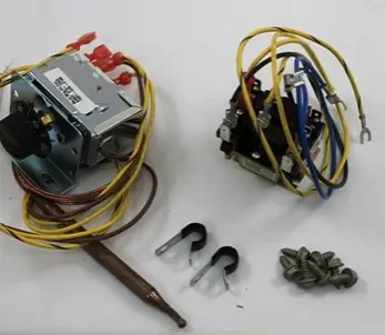
The CMH-28 kit consists of:
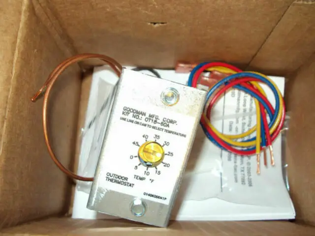
- 910-2012 Relay and Outdoor Thermostat Assembly
- 8408-048 Freeze Protect Thermostat
- 3/8″ vinyl-covered clamps
- Required fasteners
- 7960-770B Supplemental Instructions
The CMH-28 kit is for use with Bard models W18HA, W18HB, W24HA, W24HB, W30HA, W30HB, W36HA and W36HB wall-mount heat pumps.
Field-supplied tools needed:
- Appropriate personal protection equipment, including gloves and safety glasses
- 5/16″ nut driver
- T20 Torx screwdriver
- Small flat head screwdriver for securing wire in terminal blocks
Outdoor Thermostat Operation
Heat pump compressor operation at outdoor temperatures below 0° is neither desirable nor advantageous in terms of efficiency. An outdoor thermostat can be applied to take the mechanical heating (compressor) offline, and send the (compressor) signal to energize electric heat in its place (to make electric heat first stage heating). This can also be applied to limit the quantity of available electric heat. Example: Heat pump with 10KW second stage heat. Once the outdoor thermostat has switched, 15KW without compressor.
WARNING
- Electrical shock hazard.
- Disconnect the remote electric power supply or supplies before servicing.
- Failure to do so can result in serious injury or death.
- Exposed moving parts.
- Disconnect all electrical power before servicing.
- Failure to do so can result in severe injury or amputation.
- Sharp metallic edges.
- Take care and wear appropriate protective devices to avoid accidental contact with sharp edges.
- Failure to do so can result in personal injury.
Installation
- Disconnect all power to wall-mount unit.
- Remove outer and inner control panel covers.
- Remove right side condenser inlet grille.
- Remove all three front service panels.
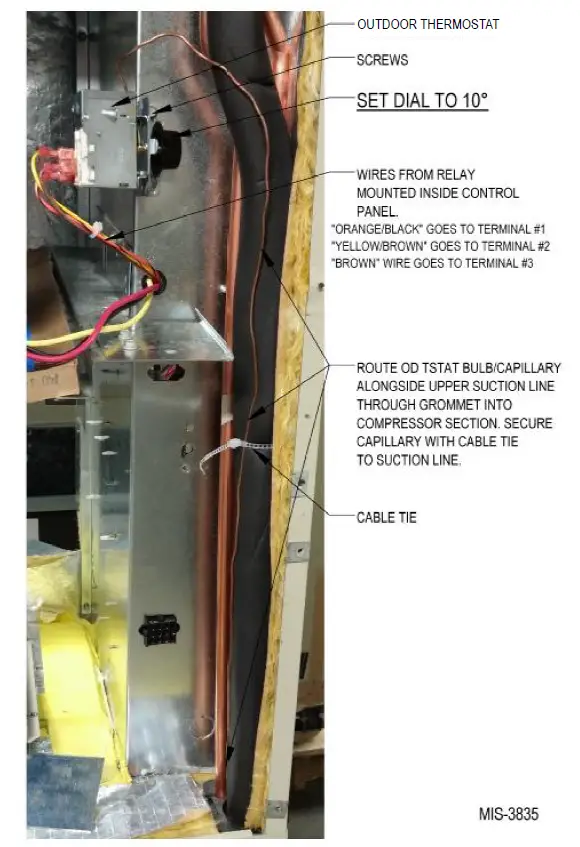
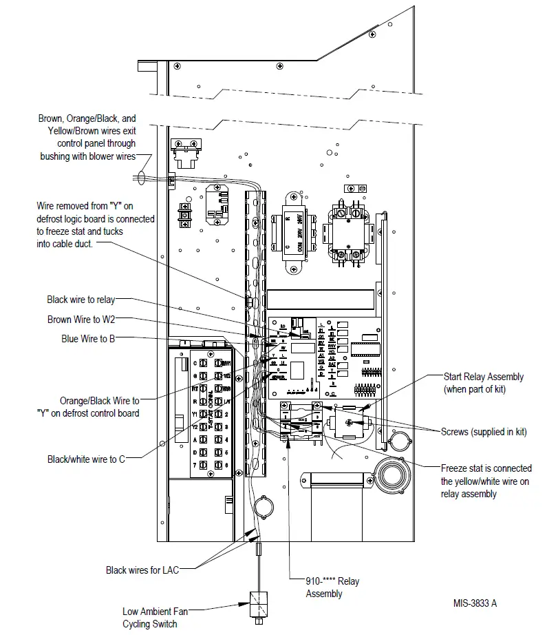
- Mount 910-2012 relay assembly into unit control panel as shown in Figure 1. Use Torx head screws included with kit to attach relay to control panel.
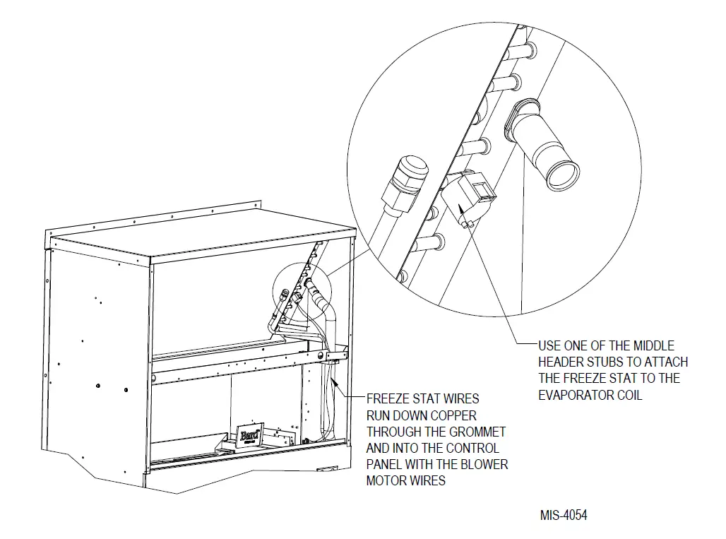
- Install freeze protect thermostat to the evaporator coil as shown in Figure 2 on page 4. Route the wires down through the bushings in the blower partition and filter partition beside the filters and into the control panel.
- Remove cover from vertical gray cable duct on control panel to allow wire harness from installed relay to route into it (see Figure 1).

 NOTE: The unit wiring diagram (included with unit literature assembly and also located on inner control panel cover) can be used to wire this kit. However, the following instructions listed here provide the necessary connections point-by-point.
 - Locate the wire that is on the Y terminal of the defrost logic control board. This wire will either be yellow/white or yellow/black depending on the unit model. Remove from its original position
and connect it to the freeze protect thermostat. Connect the other end of freeze protect thermostat to the yellow/white wire from the 910-2012 relay. - Locate the orange/black wire from the 910-2112 relay and connect it to the Y terminal on the defrost logic board.
- Locate black/white wire from relay assembly and route through cable duct to defrost control logic board. Connect the wire to the C terminal. If the heat pump is a dehum unit, remove the black/white wire already connected to C terminal and stack it back onto the black/white wire from the relay assembly.
- Locate blue wire from relay assembly and route through cable duct to defrost control logic board. Connect to B terminal. Remove blue wire already connected to B terminal and stack it back onto the blue wire from the relay assembly.
- Locate brown wire from relay assembly and route through cable duct to defrost control logic board. Connect to W2 terminal. Remove brown wire already connected to W2 terminal and stack it back onto the brown wire from the relay assembly.
- Route orange/black, yellow/brown and brown wires up the cable duct in the control panel.
After removing the permagum from around the blower motor wires, route the wires into the blower compartment and replace the permagum around all the wires (see Figures 1 and 3 on pages 3 and 5). - Locate the outdoor thermostat shipped in the CMH-28 kit along with two (2) Torx head screws. Use the two screws to attach the outdoor thermostat onto the side of the control panel adjacent to the indoor blower in the blower compartment (see Figure 3).

- Carefully unroll the capillary tube and sensing bulb of the outdoor thermostat, and route it into the condenser section through the tubing grommet in the condenser partition. Secure the capillary tubing to the insulated suction line with the supplied cable tie.
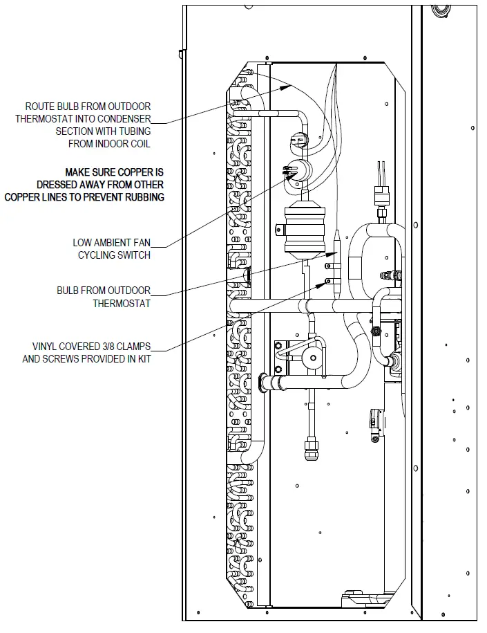
- Continue routing the outdoor thermostat bulb within the condenser section as shown in Figure 4 on page 6. Secure the bulb as per the drawing using the vinyl-covered clamps and hex head screws included in the kit. Dress the capillary tube to ensure no tube-rubs occur and secure with supplied cable ties in both the condenser and ventilation sections.

- Connect the orange/black wire to outdoor thermostat Terminal #1, the yellow/brown wire to Terminal #2 and the brown wire to Terminal #3.
- Verify outdoor thermostat setpoint. Factory default is 10°F.
- Apply “This unit is equipped with CMH-28 control module” label to the inside of the inner control panel cover above the unit wiring diagram.
- Re-install all three front service panels.
- Re-install right side condenser inlet grille.
- Re-install electrical cable duct cover.
- Re-install inner and outer control panel covers.
- Restore unit power.
 NOTE: The unit wiring diagram (included with unit literature assembly and also located on inner control panel cover) can be used to wire this kit. However, the following instructions listed here provide the necessary connections point-by-point.