![]()
INSTALLATION MANUAL
TIS POWER RELAY
6 Channels 5 Amps
Model: VLC-6CH-5A
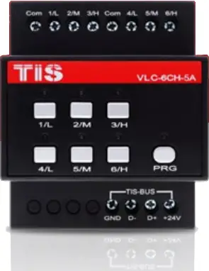
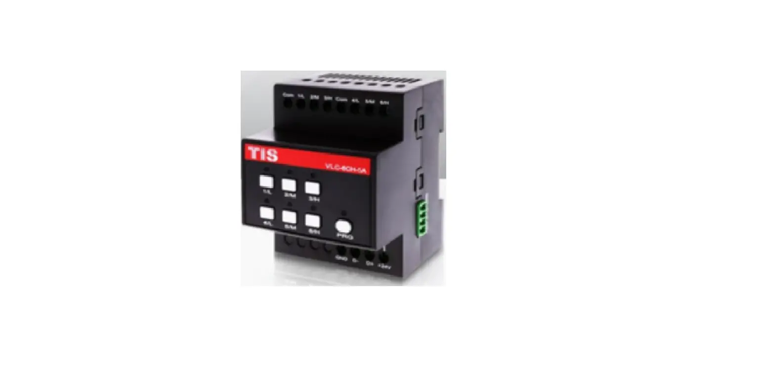
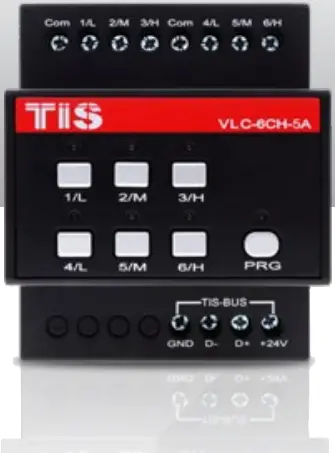
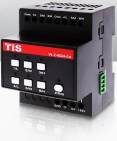
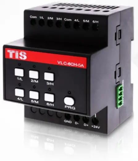
![]() PRODUCT INFORMATION
PRODUCT INFORMATION
This product is a power relay switch with electromagnet for lights’ turn ON/OFF or motors’ Open/Close function. It enables smart control over lights, sprinklers, gates, shutters and curtains, fan speed, valves, etc. and is ideal for residential and industrial applications.
| PRODUCT SPECIFICATIONS | ||
| Number of channels | 6 | |
| Nominal voltage | 0 – 230 V AC 50/60 Hz | |
| Nominal current per channel | ||
| Low current | 5 A | |
| Lighting incandescent lamp | 4 A | |
| Motors / Air condition | 3 A | |
| LED and CFL lamp | 1 A | |
| Max switching current | 5A | |
| Max Continues current | 4A | |
| Number of devices on 1 line | Max. 64 | |
| Bus voltage | 12-32 V DC | |
| Current consumption (Normal) | <20 mA / 24 V DC | |
| Current consumption (operation) | <100 mA / 24 V DC | |
| Protection | Reverse polarity protection | |
| Programming button/LED | For assignment of the physical address | |
| 1-6 buttons | Manual ON/OFF & programming | |
| By TIS bus | TIS protocol messages & commands | |
| Programming | Manual & via software | |
| Lighting control ON/OFF | 6 separately controllable channels | |
| Motor setting | Can set 3 groups of curtains (open/close) | |
| Fan speed control | Can set 2 groups of fans (low, med, high) | |
| Width × Length × Height | 76mm × 73mm × 90mm | |
| Materials | Fireproof ABS | |
| Casing color | Black | |
| Button color | Silver | |
| IP rating | IP 20 | |

![]()
 Read Instructions
We recommend that you read this Instruction Manual before installation.
 Safety instructions
Electrical equipment should only be installed and fitted by electrically skilled persons.
Failure to observe the instructions may cause damage to the device and other hazards.
These instructions are an integral part of the product and must remain with the end customer.
 Programming
This device can be tested and programmed manually. Advanced programming requires TIS Device Search software. Advanced software programming knowledge should be obtained in the advanced training courses.
 Simple Installation
DIN Rail mount facilitates installation. Fixing points are provided for installation without the use of DIN rail.
 Mounting Location
Install in a dry, well-ventilated location. Controllers may emit some mechanical noise. Take this into account when deciding on a mounting location.
 Data Cable
Use screened stranded RS485 data cable with four twisted pairs. Configure devices in a “Daisy Chain.”
Do not cut or terminate live data cables.
 Electrical Wires
The installer should adequately consider the total current consumption when selecting the wires.
Recommended wire size for load (light channels) and input wires is 2.5 -4 mm.
 Warranty
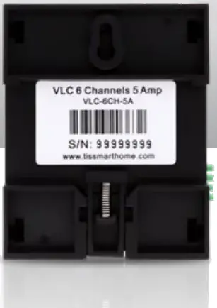
We provide a warranty as required by law. A hologram warranty seal and product serial number are provided on each device. Please send the description of the defect with Product S/N to our dealer network.
 INSTALLATION STEPS
1 ![]() Turn off the main electrical source before installation.
Turn off the main electrical source before installation.
![]() WARNING! HIGH VOLTAGE
WARNING! HIGH VOLTAGE
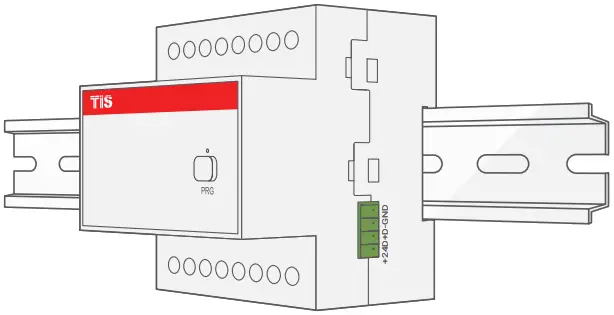
2 ![]() Mount the device on a DIN rail inside an approved enclosure. The device can also be installed without the use of DIN rail by two mounting screw holes.
Mount the device on a DIN rail inside an approved enclosure. The device can also be installed without the use of DIN rail by two mounting screw holes.
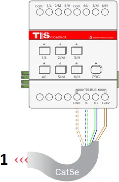
3 ![]() Connect RS485 data cable to the TIS-BUS port as per the connection diagram. No need to loop the TIS-BUS cable if 2 DIN Rail modules are connected together from the side bus train terminal.
Connect RS485 data cable to the TIS-BUS port as per the connection diagram. No need to loop the TIS-BUS cable if 2 DIN Rail modules are connected together from the side bus train terminal.
- To the TIS BUS Network
4 ![]() Complete the load connection, light, shutter, and FCU as per the following steps:
Complete the load connection, light, shutter, and FCU as per the following steps:
 LIGHTS / APPLIANCES / FLOORHEATING CONNECTION
Connect the load electrical wires to outputs 1-6. Each channel can control a maximum of 5A loads. The installer should make sure not to overload the channels.
Load neutral wire should be linked to the neutral connection in DB enclosure.
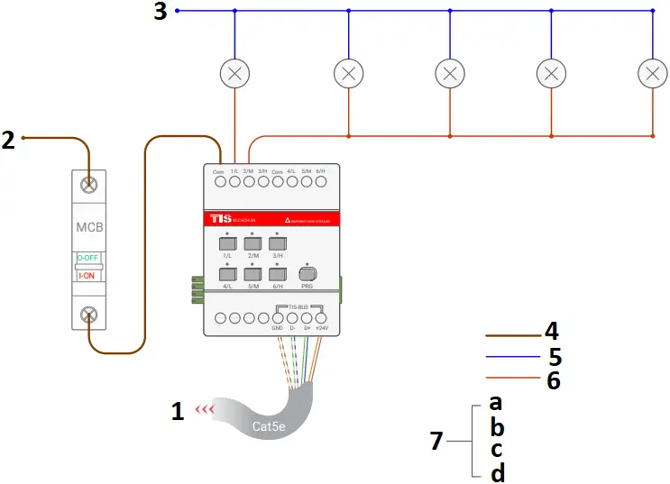
- To the TIS BUS Network
- Connect To L
- Connect To N
- 2.5 mm Electric Cable
- 1.5 mm Electric Cable
- 1.5 mm Electric Cable
- Cat5e connection
a GND(white-orange)&(white-brown)
b D-(white-green)&(white-blue)
c D+(blue-green)
d +24V(brown-orange)
 SHUTTER/CURTAIN CONNECTION
Once you combine any 2 channels as shutter/curtain, then connect the shutter-open wire to the first channel and the shutter-close wire to the second channel. The shutter neutral wire should be linked to the neutral connection in DB enclosure.
![]() WARNING: Do not connect curtain motor wires before combining (interlocking) 2 relay channels together as curtain mode to avoid causing damage to motors. Please read about how to manually program shutter/curtain pairing in this manual.
WARNING: Do not connect curtain motor wires before combining (interlocking) 2 relay channels together as curtain mode to avoid causing damage to motors. Please read about how to manually program shutter/curtain pairing in this manual.
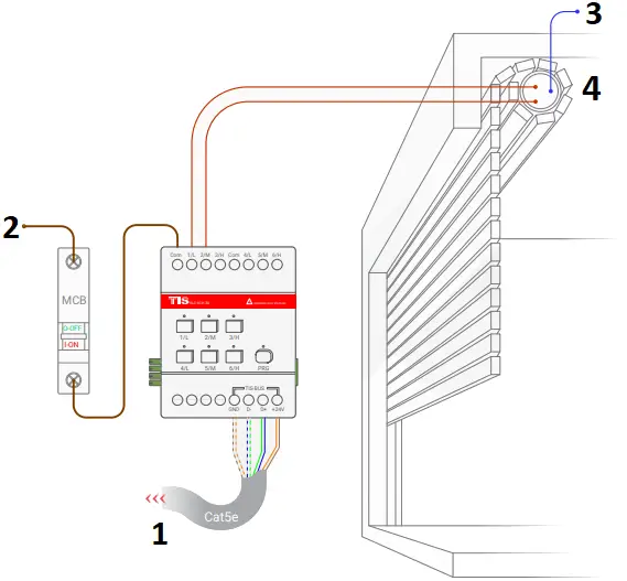
- To the TIS BUS Network
- Connect To L
- Connect To N
- 110 ~ 220 Volt
 FCU Connection
Once you combine any 3 channels as FCU, then connect the FCU (Low, Medium, High) wires to the first, second, and third channels, consecutively. The FCU neutral wire should be linked to the neutral connection of the same section.
![]() WARNING: Do not connect FCU wires before combining (interlocking) 3 relay channels together as FCU mode to avoid causing damage to FCU. Please read about how to manually program FCU pairing in this manual.
WARNING: Do not connect FCU wires before combining (interlocking) 3 relay channels together as FCU mode to avoid causing damage to FCU. Please read about how to manually program FCU pairing in this manual.
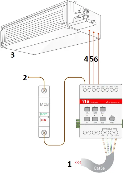
- To the TIS BUS Network
- Connect To L
- FCU
- LOW
- MEDIUM
- HIGH
5 ![]() Connect the live (supply) wire to inputs. All inputs must have an appropriate voltage source and an MCB to protect that load circuit.
Connect the live (supply) wire to inputs. All inputs must have an appropriate voltage source and an MCB to protect that load circuit.
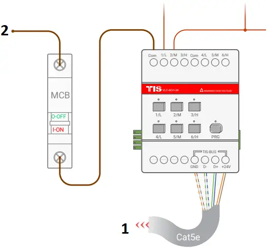
- To the TIS BUS Network
- Connect To L
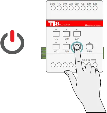
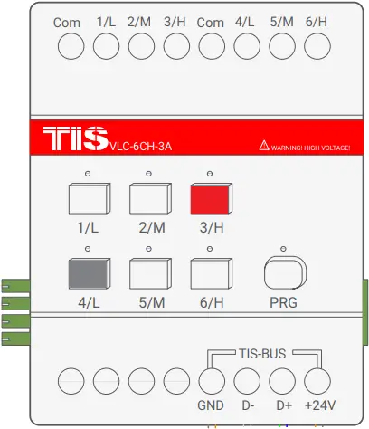
6 ![]() Turn on the power source, and then test the loads by short pressing on the device’s local override buttons 1-6.
Turn on the power source, and then test the loads by short pressing on the device’s local override buttons 1-6.
 PAIRING (MANUAL PROGRAMMING)
LIGHTS/APPLIANCES PROGRAMMING
All channels by default are used for lights/appliances control.
You can pair device light channels to any wall panels by doing the following:
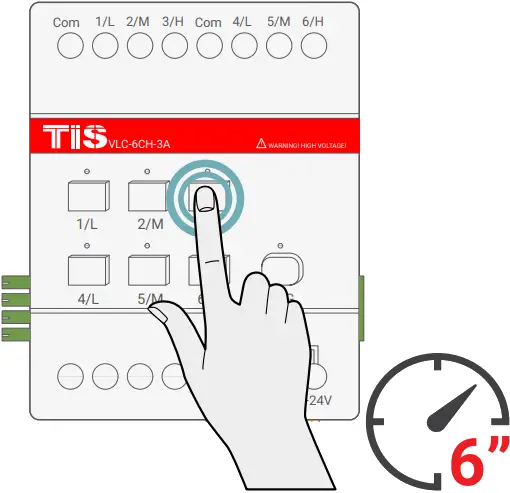
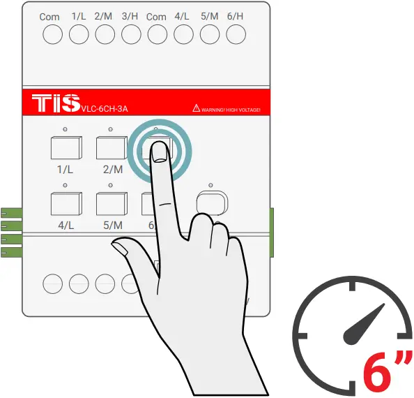
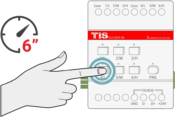
1 ![]() Long press on any buttons 1-6 for 6 seconds. The LED indicator for the pressed button will start blinking.
Long press on any buttons 1-6 for 6 seconds. The LED indicator for the pressed button will start blinking.
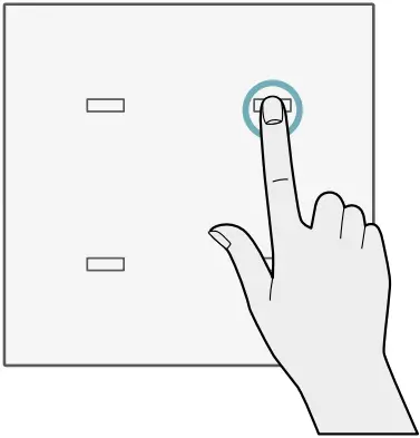
2 ![]() Short press on any wall lights buttons on the Luna, Mars, Terre or other panels.
Short press on any wall lights buttons on the Luna, Mars, Terre or other panels.
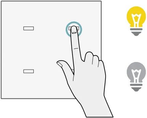
3 ![]() Test the button on the panel by short pressing it for ON/OFF.
Test the button on the panel by short pressing it for ON/OFF.
 FLOOR HEATING PROGRAMMING
1 ![]() Long press on any buttons 1-6 for 6 seconds. The LED indicator for the pressed button will start blinking.
Long press on any buttons 1-6 for 6 seconds. The LED indicator for the pressed button will start blinking.

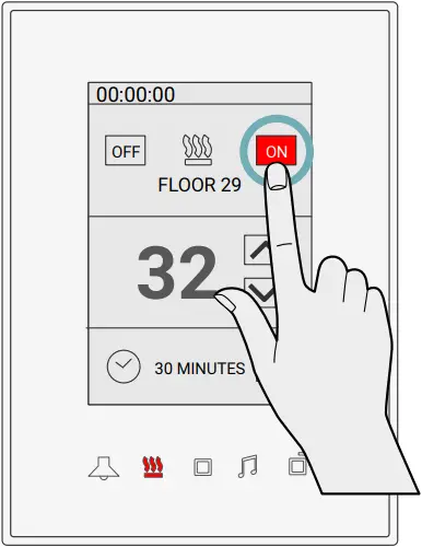
2 ![]() Go to floor heater page on any wall panel with the floor heating function, and press ON button to turn on the floor heating.
Go to floor heater page on any wall panel with the floor heating function, and press ON button to turn on the floor heating.
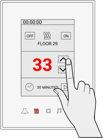
3 ![]() Test the floor heating by changing the temperature and turning it OFF/ON.
Test the floor heating by changing the temperature and turning it OFF/ON.
SHUTTER COMBINATION PROGRAMMING
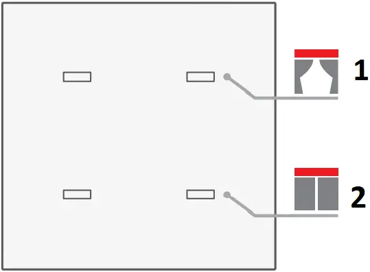
You can change any 2 channels in sequence like CH1 and CH2, Ch3 and CH4, Ch5 and CH6 to be combined (interlocked) together to work as shutter/curtain control.
To combine these 2 channels, complete the following steps manually:
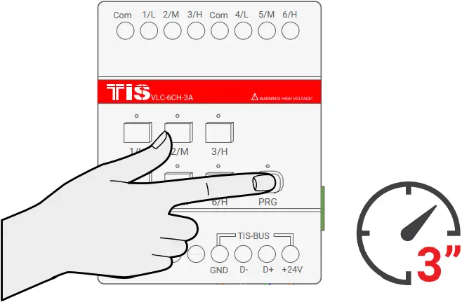
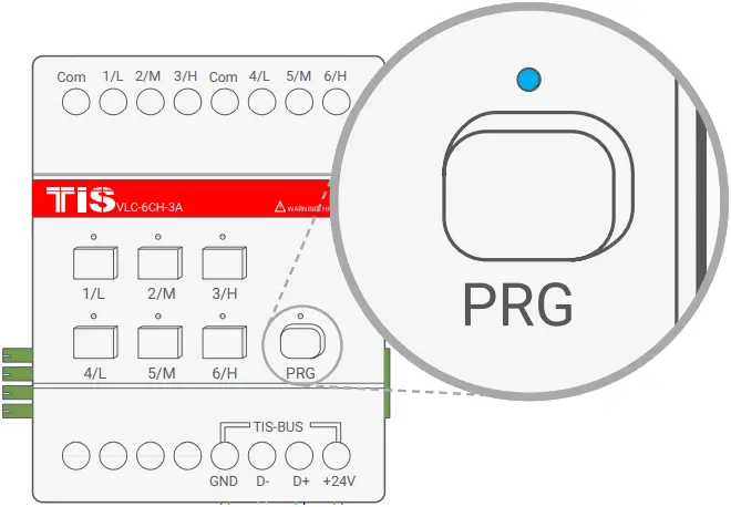
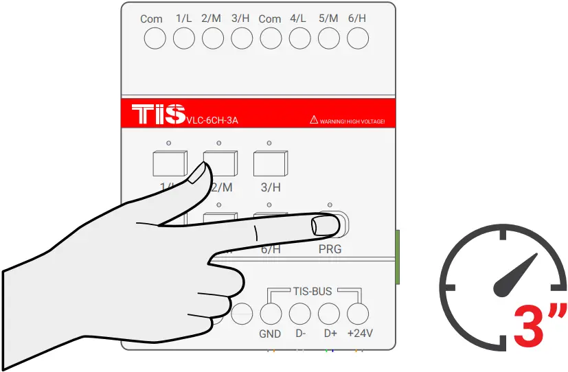
1 ![]() Press the PRG button for 3 seconds until the LED starts blinking rapidly.
Press the PRG button for 3 seconds until the LED starts blinking rapidly.
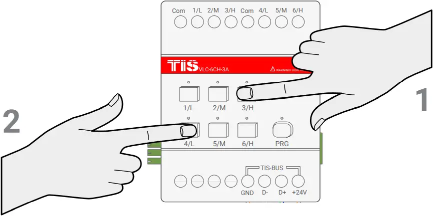
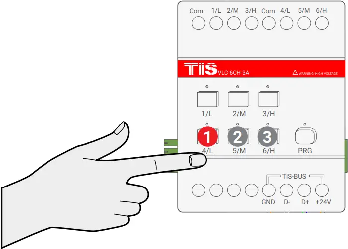
2 ![]() Short press on the first button and then the second button that you want to combine as curtain control; for example, CH3 and CH4.
Short press on the first button and then the second button that you want to combine as curtain control; for example, CH3 and CH4.
3 ![]() Wait for few seconds until the PRG LED stops blinking.
Wait for few seconds until the PRG LED stops blinking.
4 ![]() Test by turning the first button ON and then the second button. Both buttons should not turn ON together. If you see that the first button is turning the other button off, that means that your buttons are successfully combined as shutter/curtain mode.
Test by turning the first button ON and then the second button. Both buttons should not turn ON together. If you see that the first button is turning the other button off, that means that your buttons are successfully combined as shutter/curtain mode.
5 ![]() To program the curtain to any wall panel, press and hold the CH (Shutter-Open) button for 6 seconds. The LED indicator of the pressed button will start blinking,
To program the curtain to any wall panel, press and hold the CH (Shutter-Open) button for 6 seconds. The LED indicator of the pressed button will start blinking,
6 ![]() Short press on any button on the Luna, Mars, Terre or others wall panels.
Short press on any button on the Luna, Mars, Terre or others wall panels.

7 ![]() Test the button on the panel by short pressing for open/stop. Do the same to program the Close channel with another button.
Test the button on the panel by short pressing for open/stop. Do the same to program the Close channel with another button.
- Open
- Close
8 ![]() To cancel the curtain interlock and return to lighting mode, repeat steps 1-3 above.
To cancel the curtain interlock and return to lighting mode, repeat steps 1-3 above.

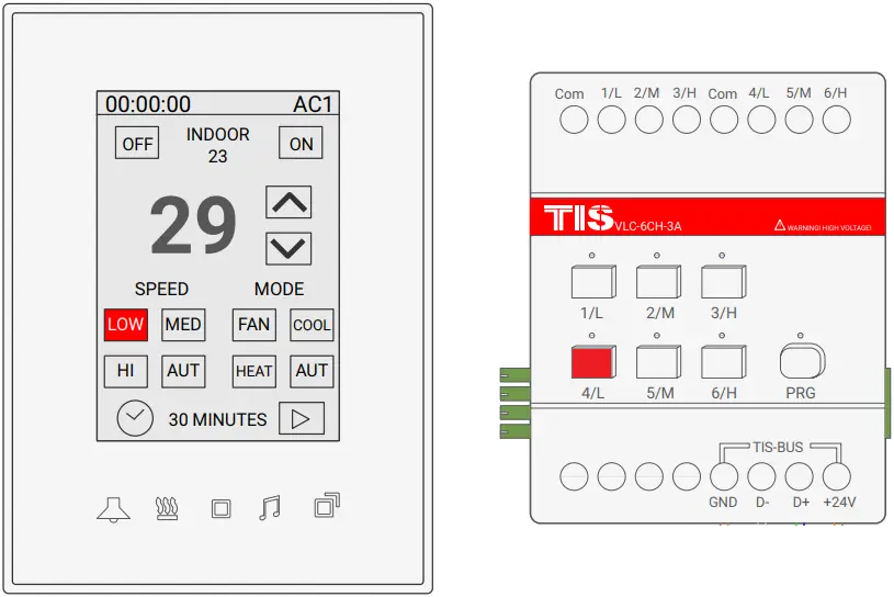
FCU COMBINATION PROGRAMMING
You can change any 3 channels in sequence like CH1-3 and CH4-6, to be combined (interlocked) together to work as FCU (Low, Medium, High).
To combine these 3 channels complete the following steps manually:
1 ![]() Press the PRG button for 3 seconds until the LED starts blinking rapidly.
Press the PRG button for 3 seconds until the LED starts blinking rapidly.
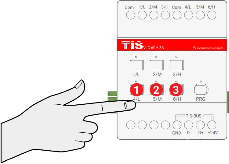
2 ![]() Short press on first button then second button then third button that you want to combine as FCU, as example CH4-6.
Short press on first button then second button then third button that you want to combine as FCU, as example CH4-6.
3 ![]() Wait for a few seconds until the PRG LED stops blinking.
Wait for a few seconds until the PRG LED stops blinking.

4 ![]() Test by turning the first button ON, then the second button, and then the third button. The buttons should not turn ON together. If you see that any button you turned ON is turning the other 2 buttons OFF, that means your buttons are successfully combined as FCU mode.
Test by turning the first button ON, then the second button, and then the third button. The buttons should not turn ON together. If you see that any button you turned ON is turning the other 2 buttons OFF, that means your buttons are successfully combined as FCU mode.
5 ![]() To program the FCU to any wall thermostat panel, press and hold the first Channel L (LOW) button for 6 seconds. The LED indicator of the pressed button will start blinking,
To program the FCU to any wall thermostat panel, press and hold the first Channel L (LOW) button for 6 seconds. The LED indicator of the pressed button will start blinking,
6 ![]() Go to the air conditioning page in your Luna TFT, Mars AC, Terre AC , or other thermostat panel, and turn the AC ON.
Go to the air conditioning page in your Luna TFT, Mars AC, Terre AC , or other thermostat panel, and turn the AC ON.
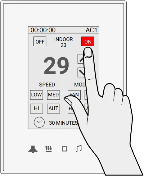
7 ![]() Test your air conditioning by changing the fan speed from low to medium to high. Your relay should respond accordingly.
Test your air conditioning by changing the fan speed from low to medium to high. Your relay should respond accordingly.
8 ![]() To cancel the FCU interlock and return back to lighting mode, repeat steps 1-3 above.
To cancel the FCU interlock and return back to lighting mode, repeat steps 1-3 above.
 TROUBLESHOOTING
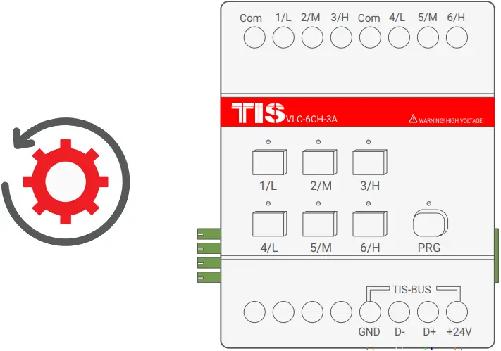
| Reason: The module’s address conflicts with another device in the TIS network. You need to press and hold the PRG button for 6 seconds so the module can get a new address. | |
| Reason: Device is not powered on; no TIS-BUS 24V supply connected to the device. | |
| Reason1: Lights’ neutral wire not connected. Reason2: Channel protection delay time is enabled in software. | |
| Reason1: TIS-BUS connection has a problem; check the wires and make sure there’s not a short in the connection. Reason2: Manual programming function disabled in the device (default is enabled). | |
| Reason 1: TIS-BUS connection has a problem; check the wires and make sure there’s not a short in the connection. Reason 2: Programming address is wrong. | |
| Reason: It is programmed as shutter/curtain combination, and running time is enabled in the software. |
 Copyright © 2022 TIS, All Rights Reserved
TIS Logo is registered trademark of TIS CONTROL.
All of the specification are subject to change without notice.
TIS CONTROL PTY LIMITED
SA , AUSTRALIA
TIS CONTROL LIMITED
Wanchai, Hong Kong
www.tiscontrol.com


