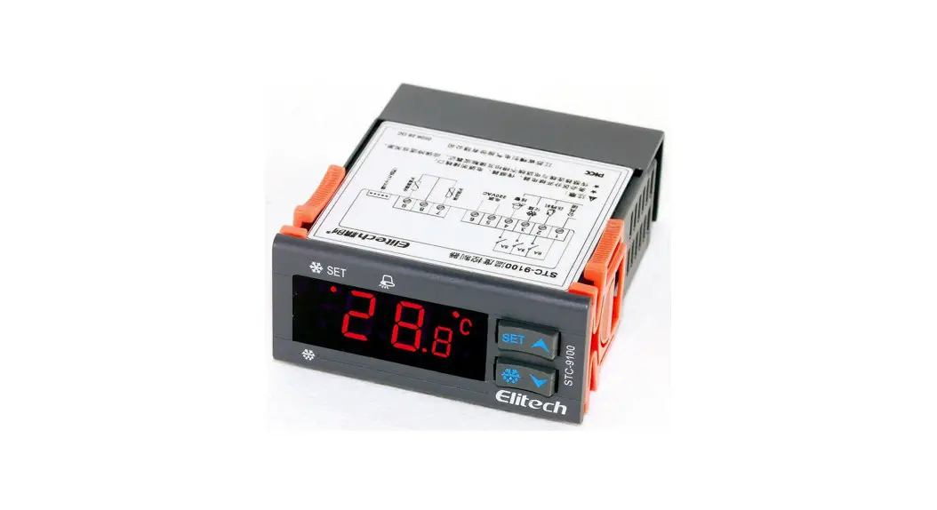
![]() STC-9100 Thermostat
STC-9100 Thermostat
Quick Start Guide
(Version 22.11.03GEN)
Video on YouTube
STC-9100 Defrosting Temperature Controller
STC-9100 defrosting temperature controller controls three loads: the refrigeration device, the defrosting unit, and the External Alarm.
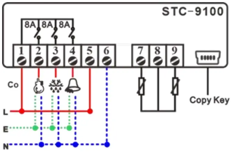
Wiring Diagram
| Live | |
| Neutral/Nuil | |
| Earth | |
| Co | Power Supply Input |
| Compressor | |
| Defrosting | |
| Alarm | |
| 7 | Room Sensor |
| 9 | Defrosting Sensor |
| 8 | Co-point of Sensos |
Set the temperature
Please learn that the room temperature was supposed to keep at the range from “F1” to “F1 + F2” (“SET” to “SET + HY”).
You can set them in both the user interface and the Admin Interface. Below is the 2nd method.
Step 1: Enter the Admin Interface: hold the [SET] key and the [![]() ] key at the same time for 10s; you will see the code “F1” (“SET”).
] key at the same time for 10s; you will see the code “F1” (“SET”).
Step 2: Press the [SET] key to check current value, and press the![]() key or the
key or the![]() key to change the F1 value;
key to change the F1 value;
Step 3: Press the [SET] key to save the new data, and back to the menu list, you will see the code “F1” (“SET”) again.
Step 4: Switch to the “F2” (“HY”) code by press the![]() key. Repeat the above 2-4 steps to update all the code you want to.
key. Repeat the above 2-4 steps to update all the code you want to.
At last: Just leave the unit alone; it will auto quit from setting mode back to normal status in 10s.
- F1 (SET): SP (Temperature Set-Point)
- F2 (HY): Temperature Hysteresis / Return Difference
- F3 (US): Upper limit for SP
- F4 (LS): Lower limit for SP
- F5 (AC): Delay Time for the Compressor and Delay time for defrosting if it was Hot Gas mode F10 = 1 (TDF = HTG)
If you found the “F1” (SET) value cannot be modified to the value you need, please adjust the F3 and F4 (the US and the LS), which are the limitation for F1 (SET).
Configure the Defrosting
This unit controls the defrosting by Time and Temperature.
Temperature Condition: the evaporation sensor temperature is lower than the preset “defrosting Stop temperature” F8 (dte), which is a significant value to prevent over defrost.
Time Condition 1: the real-time passes the preset interval time F6 (idf), a regular parameter for almost all defrosting thermostats.
Time Condition 2: If the “defrosting method” you take is the hot gas from the compressor reverse rotary when F10 = 1 (tdf = HTG), it will count the compressor’s last stops moment plus F5 (ac), which is a protective value to avoid the compressor frequently startup and stops.
The operates method is just like page 1 shows;
6) F6 (IDF): Defrosting Cycle / Interval Time
7) F7 (ADF): Defrosting Lasting/Running Time
8) F8 (DTE): Defrosting Stop Temperature
9) F9 (FDT): Defrosting Water Dripping Time
10) F10 (TDF): Defrosting Mode:
- 0 (EL): Electric-Heating.
- 1 (HTG): Hot Gas from the compressor.
11) F11 (DCT): Count mode of defrost cycle:
- 0 (RT): Cumulative time from the controller power on.
- 1 (COH): Cumulative time of the compressor working.
12) F12 (DFD): Display mode when defrosting:
A. 0 (RT): Shows the room sensor temperature display.
B. 1 (IT): Shows the evaporator sensor temp. (continue showing 10 minutes once defrosting over)
Set the External Alarm?
Unlike other defrost thermostats, which only reference the room sensor, this unit STC-9100 also monitors the evaporator sensor temperature.
Check the Alarm output options in F13 (DMO):
| Code | Description | |
| N-C/0 | The alarm output’s function was banned. | |
| A-C/1 | The alarm follows the buzzer status | press any key to stops |
| A-A/2 | It cannot be canceled before fixed all errors. | |
And then check below items
| Sensor Position | EN Code | F code | Meaning |
| Evaporator | ELL | F14 | Lower Limit |
| EOD | F15 | Time delay | |
| ELU | F16 | Upper Limit | |
| Room | ALU | F17 | Upper Limit |
| ALL | F18 | Lower Limit | |
| ALD | F19 | Time delay |
This is not a step-by-step user manual;
It just shows the key points.
The new user should read the Full-Content Version User Manual

Haswill Electronics
www.thermo-hygro.com
Copyright Haswill-Haswell All Rights Reserved


