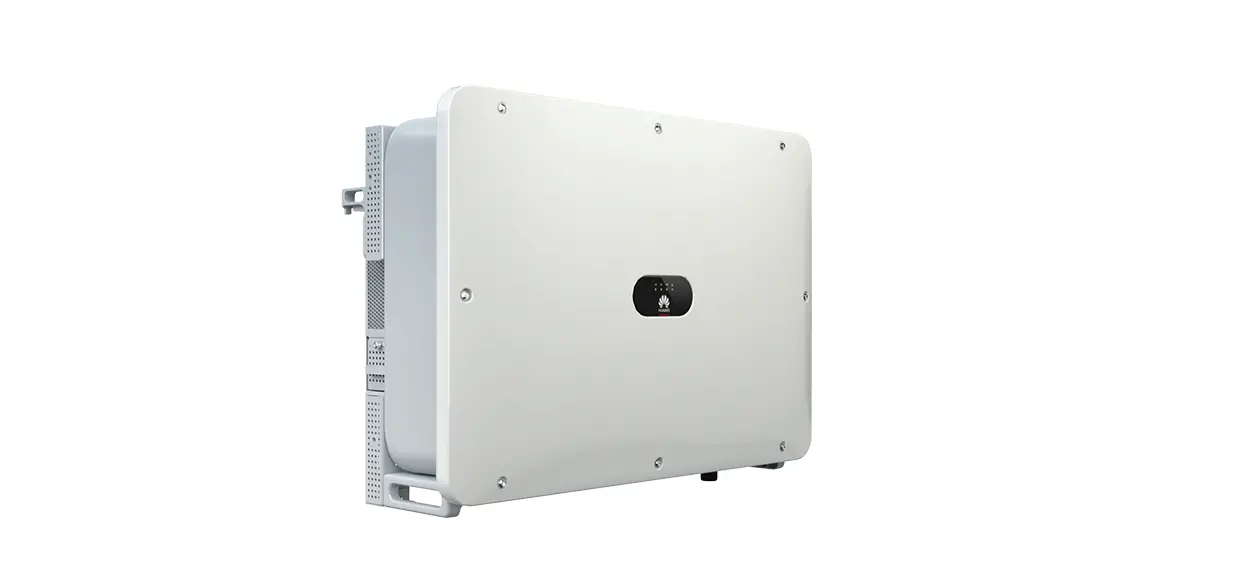
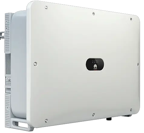
HUAWEI SUN2000-175KTL-H0 Smart PV Inverter
NOTICE
- The information in this document is subject to change without notice. Every effort has been made in the preparation of this document to ensure accuracy of the contents, but all statements, information, and recommendations in this document do not constitute a warranty of any kind, express or implied.
- Only qualified and trained electrical technicians are allowed to operate the device. Operators should understand the composition and working principles of the grid-tied PV power system and local standards.
- Before installing the device, read the user manual carefully to get familiar with product information and safety precautions. Huawei shall not be liable for any consequences caused by the violation of the storage, transportation, installation, and operation regulations specified in this document and the user manual.
- Use insulated tools when installing the device. For personal safety, wear proper personal protective equipment (PPE).
Product Overview
Front ACVACiew
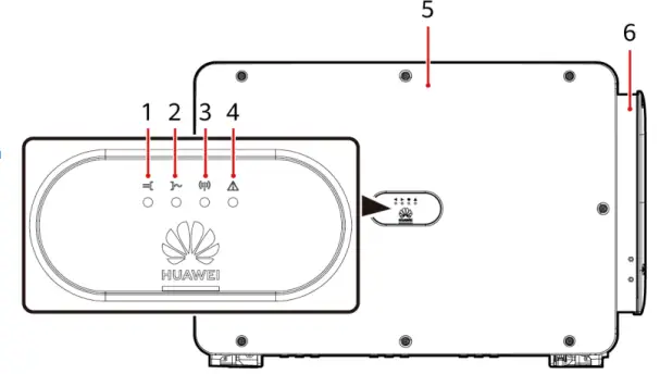
- PV connection indicator
- Grid-tied indicator
- Communication indicator
- Alarm/Maintenance indicator
- Host panel cover
- Maintenance compartment
Port Description
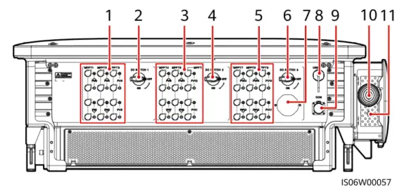
- DC input terminals (controlled by DC SWITCH 1)
- DC switch 1 (DC SWITCH 1)
- DC input terminals (controlled by DC SWITCH 2)
- DC switch 2 (DC SWITCH 2)
- DC input terminals (controlled by DC SWITCH 3)
- DC switch 3 (DC SWITCH 3)
- Ventilation valve
- USB port (USB)
- Communications port (COM)
- Hole for the AC output power cable
- Hole for the tracking system power cable
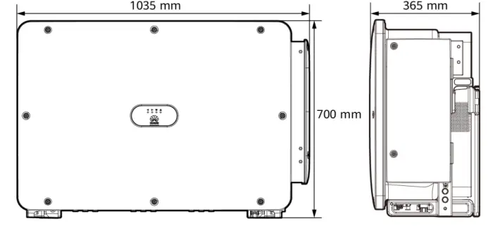
SUN2000 Dimensions
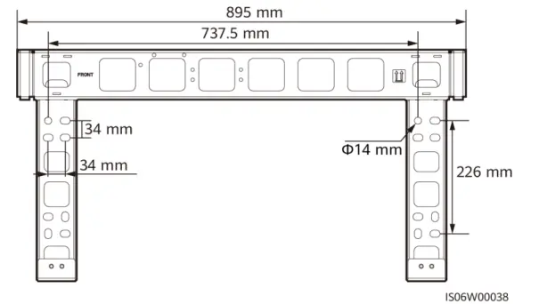
Mounting Bracket Dimensions
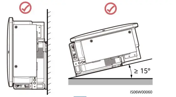
Installation Requirements
Installation Angle
Installation Space
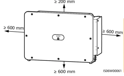
NOTE
For ease of installing the SUN2000 on the mounting bracket, connecting cables to the bottom of the SUN2000, and maintaining the SUN2000 in future, it is recommended that the bottom clearance be between 600 mm and 730 mm.
Installing the SUN2000
NOTE
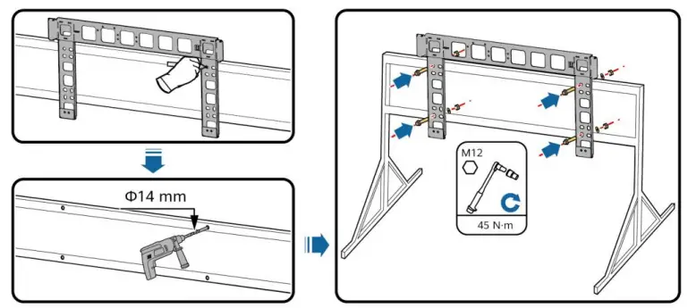
- The M12x40 bolt assemblies are delivered with the SUN2000. If the bolt assembly length does not meet the installation requirements, prepare M12 bolt assemblies by yourself and use them together with the delivered M12 nuts.
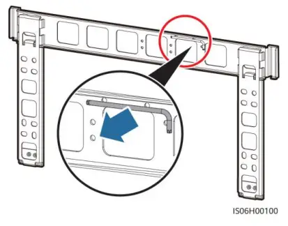
- Before installing the mounting bracket, remove the security Torx wrench from the mounting bracket and save it for later use.
- This document introduces how to install the SUN2000 on a support as an example. For details about wall-mounted installation, see the user manual.
Install the mounting bracket.
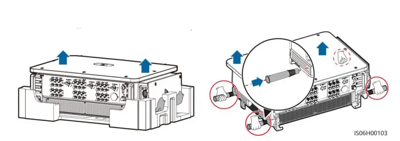
Unpack the inverter and move it to the specified position.
NOTE
Handles are packed in a fitting bag and are not delivered with the SUN2000.
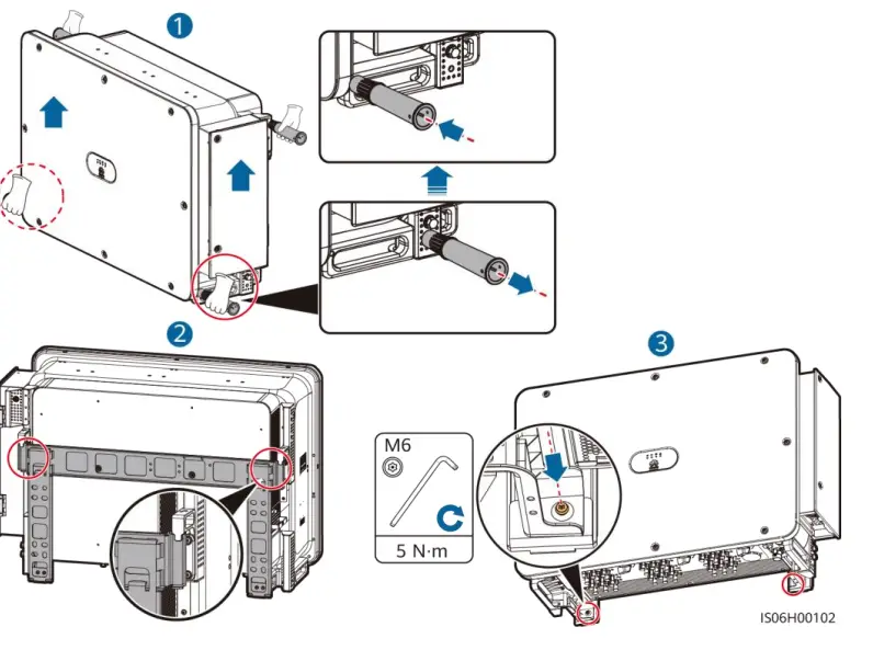
Adjust the installation positions of the handles, and install the SUN2000 on the mounting bracket.
Installing Cables
Installation Preparations
NOTE
If outdoor copper-core cables are used, select copper wiring terminals. For details about the requirements for cables and terminals of other materials, see the user manual.
| No. | Item | Type | Specifications | Description |
| 1 | PE cable | Single-core outdoor copper cable | Conductor cross- sectional area ≥ S/2a (S is the conductor cross- sectional area of the AC output power cable.) | • If you choose the ground point on the chassis shell for connecting a PE cable, prepare the PE cable. • If you choose the ground point in the maintenance compartment for connecting a PE cable, use a four-core AC output power cable and do not have to prepare a PE cable. |
| 2 | AC output power cableb | Outdoor copper cable | • Conductor cross- sectional area: 50– 240 mm2 • Cable outer diameter: 24–66 mm (multi- core); 14–32 mm (single-core) | If you choose the ground point in the maintenance compartment for connecting a PE cable, use a four-core cable. Otherwise, use a three- core cable or three single-core cables. |
| Outdoor aluminum-core cable | • Conductor cross- sectional area: 70– 240 mm2 (multi- core); 70–240 mm2 (single-core) • Cable outer diameter: 24–66 mm (multi- core); 14–32 mm (single-core) | |||
| 3 | DC input power cable | PV cable that meets the 1500 V standard | • Conductor cross- sectional area: 4–6 mm2 • Cable outer diameter: 4.7–6.4 mm | – |
| No. | Item | Type | Specifications | Description |
| 4 | RS485 communication s cable | Outdoor shielded twisted pair cable | • Conductor cross- sectional area: 0.25–1 mm2 • Cable outer diameter: 4–11 mm | When three communications cables connect to the signal cable connector, the outer diameter of the cables should be 4–8 mm. |
| 5 | (Optional) Power cable of the tracking system | Three-core outdoor copper cable with dual-layer protection | • Conductor cross- sectional area: 10 mm2 • Cable outer diameter: 15–18 mm | – |
| Note a: The value is valid only if the conductors of the PE cable and AC power cable use the same material. If the materials are different, ensure that the conductor cross-sectional area of the PE cable produces a conductance equivalent to that of the area S/2. The specifications of the PE cable are subject to this table or calculated according to IEC 60364-5-54. Note b: You are advised to use a soft cable to prevent poor terminal contact due to the bending stress of the cable. | ||||
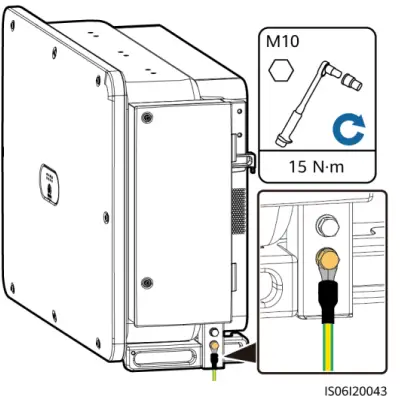
Installing the PE Cable
NOTE
- It is recommended that the PE cable be connected to a nearby PE point. Connect the PE points of all SUN2000s in the same PV array to ensure equipotential connections to PE cables.
- To enhance the corrosion resistance of a ground terminal, you are advised to apply silica gel or paint on it after connecting the PE cable.
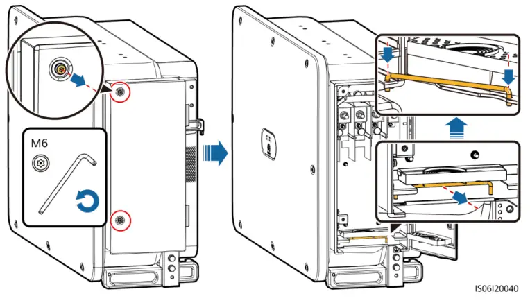
Opening the Maintenance Compartment Door
WARNING
- Do not open the host panel of the SUN2000.
- Before opening the SUN2000 maintenance compartment door, turn off the downstream AC output switch and three DC switches at the bottom.
- Do not open the maintenance compartment door in rainy or snowy days. If you must, take protective measures to prevent rain or snow from entering the maintenance compartment.
- Do not leave unused screws in the maintenance compartment.
- Loosen the screws on the maintenance compartment door.
- Open the maintenance compartment door and adjust the support bar.

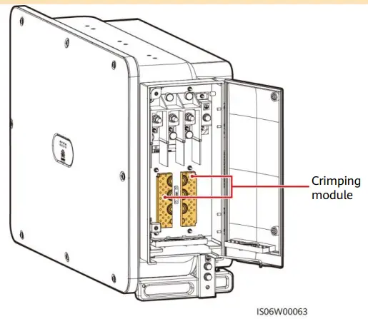
- Remove the crimping modules that are bound in the maintenance compartment and save them properly for future use.
NOTE
For some models, a three-hole rubber plug is bound in the maintenance compartment. After removing the rubber plug, save it properly for future use
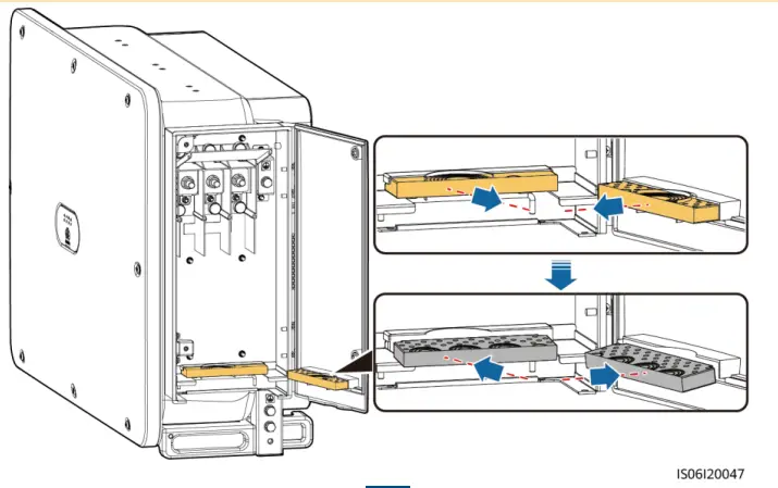
(Optional) Replacing the Crimping Module
NOTE
If the AC output power cable has a single core, replace the crimping module.
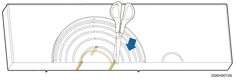
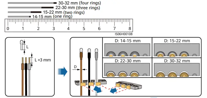
Removing the Rubber Rings from the Crimping Module
NOTE
Use scissors to cut off the joints of the rubber rings to remove them. All rubber rings are removed in the same way.
(Optional) Installing the Solar Tracker Power Cable
NOTE
- A switch-disconnector-fuse or fuse-switch-disconnector with a voltage of no less than 800 V, current of 16 A, and protection type of gM needs to be installed between the SUN2000 and the tracker controller for protection.
- The cable between the wiring terminal on the power cable and the switch-disconnector-fuse or fuse-switch-disconnector should be less than or equal to 2.5 meters.
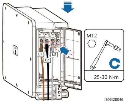
Installing AC Output Power Cables
NOTE
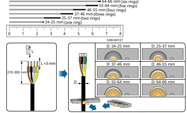
- Remove the corresponding rubber rings in strict accordance with the cable diameter, and ensure that the crimping module is not damaged. Otherwise the protection level of the solar inverter will be affected.
- Ensure that AC terminations provide firm and solid electrical connections. Failing to do so may cause SUN2000 malfunction and damage to its terminal block, even starting thermal events.
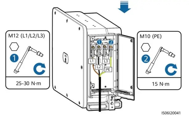
- If the AC output power cables are subject to a pulling force because the inverter is not installed stably, ensure that the last cable that bears the stress is the PE cable.
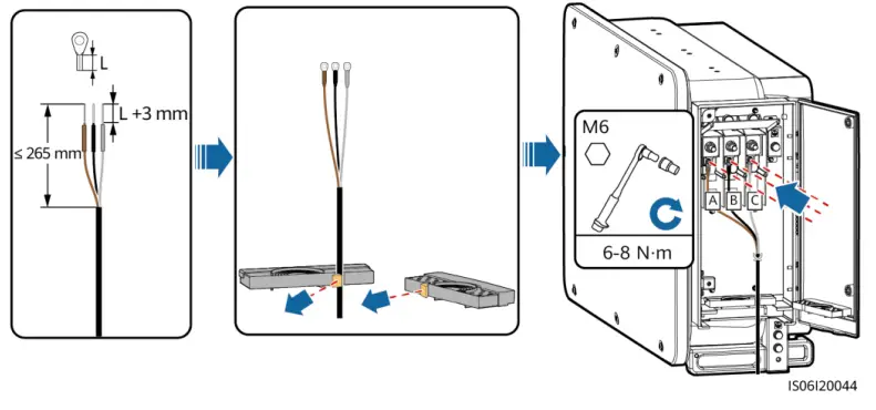
Multi-core Cable (Four-Core Cable Is Used as an Example)
Single-core Cable
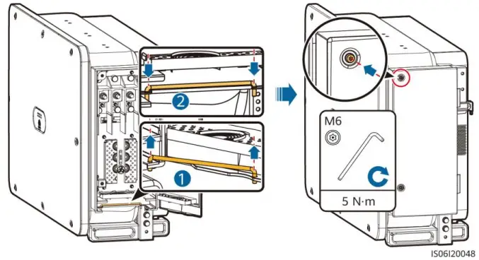
Closing the Maintenance Compartment Door
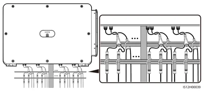
Installing DC Input Power Cables
Wiring Description of Y-branch Connectors
NOTE
- Y-branch connectors can be purchased from Huawei or the manufacturers based on the following recommended models: If the rated current of the fuse of the Y-branch connector is 15 A, the recommended model is 904095944 (Luxshare) or A040959443039 (Comlink); if the rated current of the fuse of the Y-branch connector is 20 A, the recommended model is 904095945 (Luxshare) or A040959453039 (Comlink).
- When connecting cables to recommended Y-branch connectors, ensure that the connectors to be paired match each other and are from the same manufacturer. Otherwise, the contact resistance of the connectors may exceed the allowed value. In this case, the connectors may be heated and oxidized, which may cause faults.
- Ensure that the locking nuts of all connectors are tightened.
- Do not bind more than three fuse enclosures together. Otherwise, the fuses and their enclosures may be damaged due to overheating. It is recommended that a clearance of 10 mm or more be reserved between fuse enclosures. You are advised not to bind the fuse enclosures with other heat emitting conductors.
Wiring rules:
- The PV+ on the string side must be connected to the PV+ on the SUN2000 side, and the PV–on the string side must be connected to the PV– on the SUN2000 side.
- Preferentially and evenly connect the Y-branch connectors to the MPPTs controlled by DC SWITCH 2 or DC SWITCH 3.
| Number of Y- branch Connector Sets | Recommended MPPT to Be Connected | Number of Y-branch Connector Sets | Recommended MPPT to Be Connected |
| 1 | MPPT9 | 2 | MPPT6, MPPT9 |
| 3 | MPPT6, MPPT7, MPPT9 | 4 | MPPT4, MPPT6, MPPT7, MPPT9 |
| 5 | MPPT4, MPPT6, MPPT7, MPPT8, MPPT9 | 6 | MPPT4, MPPT5, MPPT6, MPPT7, MPPT8, MPPT9 |
| 7 | MPPT3, MPPT4, MPPT5, MPPT6, MPPT7, MPPT8, MPPT9 | 8 | MPPT1, MPPT3, MPPT4, MPPT5, MPPT6, MPPT7, MPPT8, MPPT9 |
| 9 | MPPT1, MPPT2, MPPT3, MPPT4, MPPT5, MPPT6, MPPT7, MPPT8, MPPT9 | N/A | N/A |
Y-branch Connector Solution
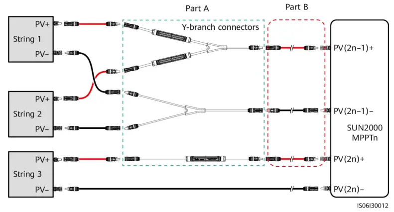
| Scenario | Model of Y-branch Connector (Part A) | Connection Description |
| Connecting Y- branch connectors to the PV strings (recommended) | All models | Use the DC terminals delivered with the SUN2000s to connect part B to the SUN2000s. |
|
Connecting Y- branch connectors to the SUN2000 | Models recommended by Huawei | Part A can be directly connected to the SUN2000, and part B is not needed. |
|
Other models | To ensure that the terminals of part A match the DC terminals of the SUN2000, part B is needed to connect part A to the SUN2000. Use the DC terminals delivered with the SUN2000 to connect part B to the SUN2000. |
NOTE
- It is recommended that the Y-branch connectors be connected from the PV string side and tied to the PV trackers.
- The DC input terminals of the solar inverter are prone to damage under stress. When Y-branch connectors are connected to the solar inverter, bind and secure the connectors to minimize stress on the DC input terminals.
- Do not place the Y-branch connector harness on the ground. A safe distance must be reserved between the Y-branch connector harness and the ground to avoid impact caused by water on the ground to the harness.
Recommended tying solution:
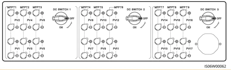
Selecting DC Input Terminals
NOTE
The SUN2000 has three DC switches (DC SWITCH 1, DC SWITCH 2, and DC SWITCH3). DC SWITCH 1 controls routes 1–6 of DC input terminals, DC SWITCH 2 routes 7–12, and DC SWITCH 3 routes 13–18.
Select DC input terminals according to the following rules:
- Evenly distribute the DC input power cables to the DC input terminals controlled by the three DC switches. DC SWITCH 1 is preferred.
- Maximize the number of connected MPPT circuits.
WARNING
Ensure that the PV module output is well insulated to ground.
NOTE
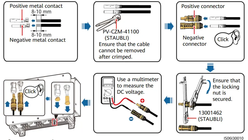
- Use the MC4 EVO2 PV connectors delivered with the SUN2000. If the PV connectors are lost or damaged, purchase the connectors of the same model. The device damage caused by incompatible PV connectors is beyond the warranty scope.
- Before connecting DC input power cables, label the cable polarities to ensure correct cable connections. If the cables are connected incorrectly, the SUN2000 may be damaged.
- Measure the voltage at the DC input end using a multimeter. If the voltage is a negative value, the DC input polarity is incorrect. Correct the polarity. If the voltage is greater than 1500 V, too many PV modules are configured to the same string. Remove some PV modules.
- If polarity of the DC input power cable is reversed and the DC switch is ON, do not turn off the DC switch immediately or unplug positive and negative connectors. The device may be damaged if you do not follow the instruction. The caused equipment damage is beyond the warranty scope. Wait until the solar irradiance declines and the PV string current reduces to below 0.5 A, and then turn off the three DC switches and remove the positive and negative connectors. Correct the string polarity before reconnecting the string to the SUN2000.
- For models of the crimping tool and removal wrench, use the recommended model or contact your Staubli dealer.
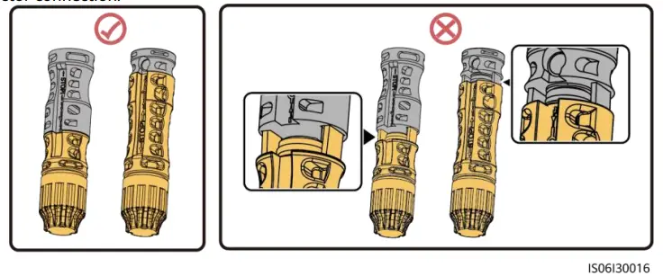
- Connect the PV string connector to the inverter connector, and then pull back the PV string connector along the axial direction to check whether the connectors are securely connected.
- The connector must be securely connected. Damages caused by improper connection are not covered under the warranty.
Installing a DC input power cable
Installing the RS485 Communications Cable
NOTE
When routing communications cables, separate communications cables from power cables to prevent communication from being affected.
Communication Port Pin Definition
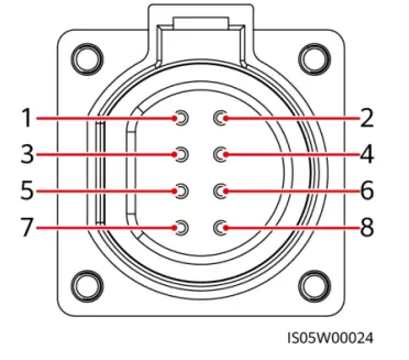
| Port | Pin | Definition | Pin | Definition | Description |
| RS485-1 | 1 | RS485A IN, RS485 differential signal+ | 2 | RS485A OUT, RS485 differential signal+ | Used for cascading inverters or connecting to devices such as the SmartLogger. |
| 3 | RS485B, RS485 differential signal– | 4 | RS485B, RS485 differential signal– | ||
| PE | 5 | PE, shielding ground | 6 | PE, shielding ground | – |
| RS485-2 | 7 | RS485A, RS485 differential signal+ | 8 | RS485B, RS485 differential signal– | Used for connecting to RS485 slave devices. |
NOTE
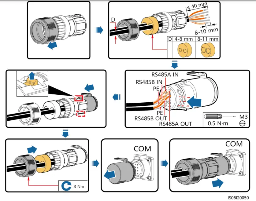
When using the four-hole rubber plug, block the unused cable hole with a plug, and then tighten the locking cap.
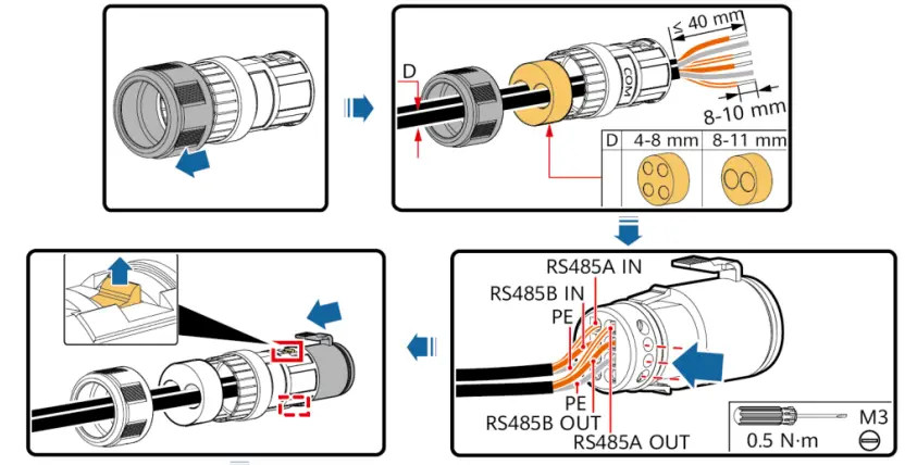
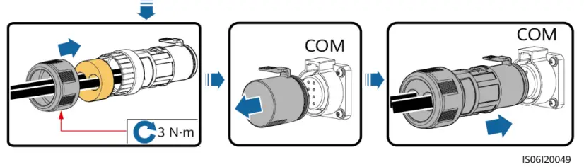
Connecting Communications Cables (4–8 mm Two-Hole Rubber Plug)
NOTE
If three communications cables are to be connected, use the three-hole rubber plug that is bound in the maintenance compartment.
Verifying the Installation
- The SUN2000 is installed correctly and securely.
- The DC switches and downstream AC switch are OFF.
- All ground cables are connected securely, without open circuits or short circuits.
- AC output power cables are connected correctly and securely, without open circuits or short circuits.
- DC input power cables are connected correctly and securely, without open circuits or shor circuits.
- The RS485 communications cable is connected correctly and securely.
- The maintenance compartment door is closed and the door screws are tightened.
- Unused DC input terminals are sealed.
- Unused USB ports are plugged with watertight caps.
Powering On the System
NOTE
Before turning on the AC switch between the SUN2000 and the power grid, use a multimeter to check that the AC voltage is within the specified range.
- Turn on the AC switch between the SUN2000 and the power grid.
- Set DC SWITCH 1 (MAIN SWITCH) at the bottom of the SUN2000 chassis to ON.
- Check the status of LED 1. If it is steady green, set DC SWITCH 2 and DC SWITCH 3 to ON.
- Observe the LED indicators to check the SUN2000 operating status.
NOTE
- Blinking at short intervals (on for 0.2s and then off for 0.2s).
- Blinking at long intervals (on for 1s and then off for 1s).
| Display Category | Indicator Status | Description | |
| PV indication
| LED1 | LED4 | – |
| Steady green | – | At least one PV string is properly connected, and the DC input voltage of the corresponding MPPT circuit is higher than or equal to 500 V. | |
| Blinking green at short intervals | Steady red | An environmental fault occurs at DC side. | |
| Off | – | The SUN2000 disconnects from all PV strings, or the DC input voltage of each MPPT circuit is less than 500 V. | |
| Grid-tied indication
| LED2 | LED4 | – |
| Steady green | – | The SUN2000 has connected to the power grid. | |
| Blinking green at short intervals | Steady red | An environmental fault occurs at AC side. | |
| Off | – | The SUN2000 does not connect to the power grid. | |
| Communications indication
| LED3 | – | |
| Blinking green at short intervals | The SUN2000 receives data over RS485 or MBUS communication. | ||
| Off | The SUN2000 has not received data over RS485 or MBUS communication for 10 seconds. | ||
| Display Category | Indicator Status | Description |
| Alarm/O&M indication
| LED4 | – |
| Steady red | A warning alarm is generated. | |
| Blinking red at short intervals | A minor alarm is generated. | |
| Blinking red at long intervals | A major alarm is generated. | |
| Steady green | Local maintenance succeeds. | |
| Blinking green at long intervals | In local maintenance or shuts down over a command. | |
| Blinking green at short intervals | Local maintenance fails. | |
| Off | No alarm is generated, and no local maintenance operations are performed. |
SUN2000 APP
NOTE
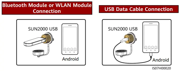
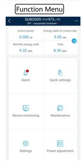
- The SUN2000 app is a mobile phone app that communicates with the solar inverter over a WLAN module, a Bluetooth module, or a USB data cable. As a convenient local monitoring and maintenance platform, it allows for querying alarms, configuring parameters, and performing routine maintenance. The app is named SUN2000.
- Go to Huawei app store (https://appstore.huawei.com), search for SUN2000, and download the app installation package. You can also scan the QR code (https://appgallery.cloud.huawei.com/appdl/C10279542) to download the installation package.
- Connect the WLAN module, Bluetooth module, or USB data cable to the USB port on the solar inverter to ensure that the solar inverter can communicate with the SUN2000 app.
NOTE
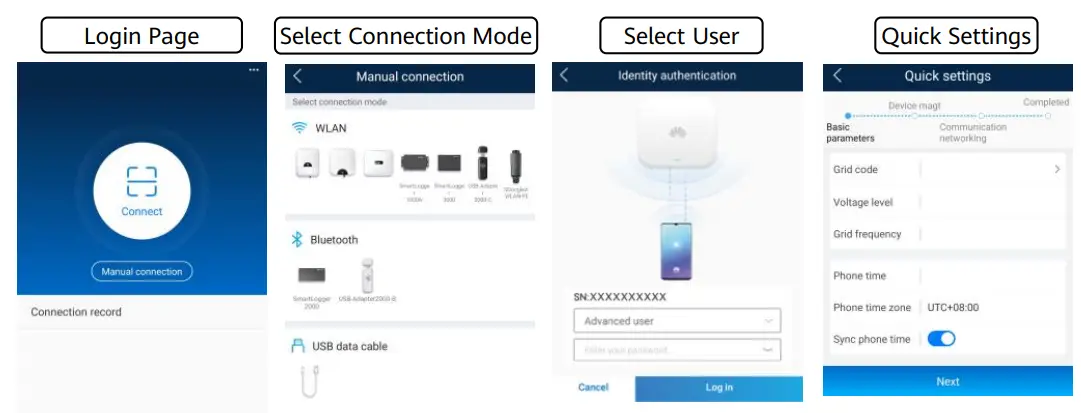
- The screenshots in this document correspond to app version 3.2.00.013 (this app is available only on Android phones currently).
- When the WLAN connection is used, the initial name of the WLAN hotspot is Adapter-WLAN module SN, and the initial password is Changeme.
- The initial password to log in to the app for Common User, Advanced User, and Special User is 00000a.
- Use the initial password upon first power-on and change it immediately after login. To ensure account security, change the password periodically and keep the new password in mind. Not changing the initial password may cause password disclosure. A password left unchanged for a long period of time may be stolen or cracked. If a password is lost, devices cannot be accessed. In these cases, the user is liable for any loss caused to the PV plant.
- Set the correct grid code based on the application area and scenario of the solar inverter.
Grid Code Mapping Table
| No. | Grid Code | Description | SUN2000- 175KTL-H0 | SUN2000- 185KTL-INH0 | SUN2000- 185KTL-H1 |
| 1 | CHINA_MV800 | China medium-voltage power grid | Supported | – | – |
| 2 | G59-England-MV800 | G59 medium-voltage power grid | – | – | Supported |
| 3 | AS4777-MV800 | Australia medium-voltage power grid | – | – | Supported |
| 4 | INDIA-MV800 | India medium-voltage power grid | – | Supported | – |
| 5 | IEC61727-MV800 | IEC61727 medium-voltage power grid (50 Hz) | – | Supported | Supported |
| 6 | BDEW-MV800 | Germany medium-voltage power grid | – | – | Supported |
| 7 | ABNT NBR 16149- MV800 | Brazil medium-voltage power grid | – | – | Supported |
| 8 | UTE C 15-712-1- MV800 | France medium-voltage power grid | – | – | Supported |
| 9 | Chile-MV800 | Chile medium-voltage power grid | – | – | Supported |
| 10 | EN50438-TR-MV800 | Turkey medium-voltage power grid | – | – | Supported |
| 11 | TAI-PEA-MV800 | Thailand PEA medium- voltage power grid | – | – | Supported |
| 12 | Philippines-MV800 | Philippines medium-voltage power grid | – | – | Supported |
| 13 | Malaysian-MV800 | Malaysia medium-voltage power grid | – | – | Supported |
| 14 | NRS-097-2-1-MV800 | South Africa medium-voltage power grid | – | – | Supported |
| 15 | SA_RPPs-MV800 | South Africa RPPs medium- voltage power grid | – | – | Supported |
| 16 | Jordan-Transmission- MV800 | Jordan power transmission network medium-voltage power grid | – | – | Supported |
| 17 | Jordan-Distribution- MV800 | Jordan power distribution network medium-voltage power grid | – | – | Supported |
| 18 | Egypt ETEC-MV800 | Egypt medium-voltage power grid | – | – | Supported |
| No. | Grid Code | Description | SUN2000- 175KTL-H0 | SUN2000- 185KTL-INH0 | SUN2000- 185KTL-H1 |
| 19 | DUBAI-MV800 | Dubai medium-voltage power grid | – | – | Supported |
| 20 | SAUDI-MV800 | Saudi Arabia medium- voltage power grid | – | – | Supported |
| 21 | EN50438_IE-MV800 | Ireland medium-voltage power grid | – | – | Supported |
| 22 | CLC/TS50549_IE- MV800 | Ireland medium-voltage power grid (CLC/TS50549) | – | – | Supported |
| 23 | Northern Ireland- MV800 | Northern Ireland medium- voltage power grid | – | – | Supported |
| 24 | CEI0-21-MV800 | Italy medium-voltage power grid (CEI0-21) | – | – | Supported |
| 25 | IEC 61727-MV800- 60HZ | General medium-voltage power grid | – | Supported | Supported |
| 26 | Pakistan-MV800 | Pakistan medium-voltage power grid | – | – | Supported |
| 27 | BRASIL-ANEEL- MV800 | Brazil medium-voltage power grid | – | – | Supported |
| 28 | CEI0-16-MV800 | Italy medium-voltage power grid | – | – | Supported |
| 29 | ZAMBIA-MV800 | Zambia medium-voltage power grid | – | – | Supported |
| 30 | KENYA_ETHIOPIA_M V800 | Kenya low-voltage and Ethiopia medium-voltage power grid | – | – | Supported |
| 31 | NAMIBIA_MV800 | Namibia medium-voltage power grid | – | – | Supported |
| 32 | Cameroon-MV800 | Cameroon medium-voltage power grid | – | – | Supported |
| 33 | NIGERIA-MV800 | Nigeria medium-voltage power grid | – | – | Supported |
| 34 | ABUDHABI-MV800 | Abu Dhabi medium-voltage power grid | – | – | Supported |
| 35 | LEBANON-MV800 | Lebanon medium-voltage power grid | – | – | Supported |
| 36 | ARGENTINA-MV800 | Argentina medium-voltage power grid | – | – | Supported |
| 37 | Jordan-Transmission- HV800 | Jordan high-voltage and medium-voltage power grid | – | – | Supported |
| No. | Grid Code | Description | SUN2000- 175KTL-H0 | SUN2000- 185KTL-INH0 | SUN2000- 185KTL-H1 |
| 38 | TUNISIA-MV800 | Tunisia medium-voltage power grid | – | – | Supported |
| 39 | AUSTRALIA-NER- MV800 | Australia NER standard medium-voltage power grid | – | – | Supported |
| 40 | VDE-AR-N4120_HV800 | VDE4120 standard medium-voltage power grid | – | – | Supported |
| 41 | Nicaragua-MV800 | Nicaragua medium- voltage power grid | – | – | Supported |
| 42 | Custom-MV800-50Hz | Reserved | – | – | Supported |
| 43 | RD1699/661-MV800 | Spain medium-voltage power grid | – | – | Supported |
| 44 | PO12.3-MV800 | Spain medium-voltage power grid | – | – | Supported |
| 45 | Vietnam-MV800 | Vietnam medium-voltage power grid | – | – | Supported |
| 46 | CHILE-PMGD-MV800 | Chile PMGD medium- voltage power grid (800 V) | – | – | Supported |
| 47 | GHANA-MV800 | Ghana medium-voltage power grid (800 V) | – | – | Supported |
| 48 | OMAN-MV800 | Oman medium-voltage power grid | – | – | Supported |
| 49 | KUWAIT-MV800 | Kuwait medium-voltage power grid | – | – | Supported |
| 50 | BANGLADESH-MV800 | Bangladesh medium- voltage power grid | – | – | Supported |
| 51 | BAHRAIN-MV800 | Bahrain medium-voltage power grid | – | – | Supported |
| 52 | KAZAKHSTAN-MV800 | Kazakhstan medium- voltage power grid | – | – | Supported |
| 53 | Oman-PDO-MV800 | Oman PDO medium- voltage power grid | – | – | Supported |
| 54 | TAI-MEA-MV800 | Thailand medium-voltage power grid | – | – | Supported |
NOTE
The grid codes are subject to change. The listed codes are for your reference only.
Huawei Technologies Co., Ltd.
Huawei Industrial Base, Bantian, Longgang, Shenzhen 518129, People’s Republic of China solar.huawei.com


