SUN2000-(100KTL, 110KTL, 115KTL)-M2
Quick Guide
Issue: 01
Part Number: 31500HMG![]()
Date: 2022-05-20
HUAWEI TECHNOLOGIES CO., LTD.
NOTICE
- The information in this document is subject to change without notice. Every effort has been made in the preparation of this document to ensure accuracy of the contents, but all statements, information, and recommendations in this document do not constitute a warranty of any kind, express or implied.
- Only certified electricians are allowed to operate the device. Operation personnel should understand the composition and working principles of the grid-tied PV power system and local regulations.
- Before installing the device, read the user manual carefully to get familiar with product information and safety precautions. Device damage caused by failure to abide by the storage, transportation, installation, and operation guidelines specified in this document and the user manual is not covered under the product warranty.
- Use insulated tools when installing the device. For personal safety, wear proper personal protective equipment (PPE).
1 Overview
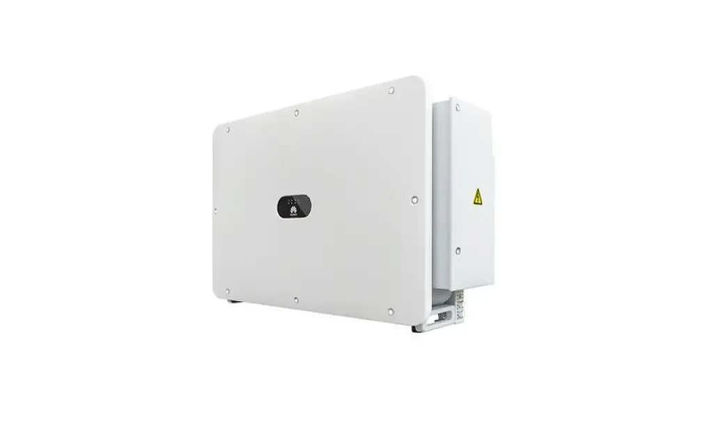
Appearance
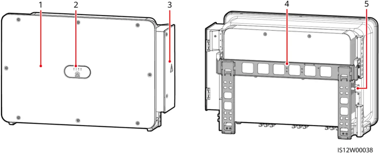
(1) Panel (2) LED indicators
(3) Maintenance compartment door (4) Mounting bracket
(5) External fan tray
Port Description
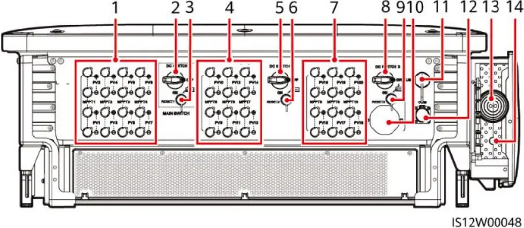
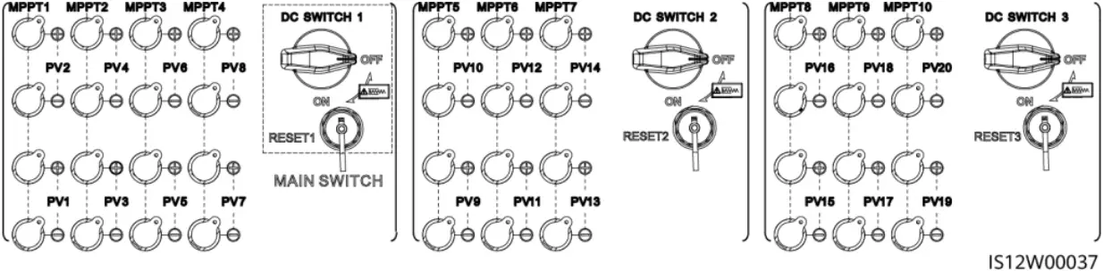
(1) DC input terminal group 1 (PV1–PV8, controlled by DC SWITCH 1)
(2) DC switch 1 (DC SWITCH 1)
(3) Reset button 1 (RESET 1)
(4) DC input terminal group 2 (PV9–PV14, controlled by DC SWITCH 2)
Copyright © Huawei Technologies Co., Ltd. 2022.
All rights reserved.
(5) DC switch 2 (DC SWITCH 2)
(6) Reset button 2 (RESET 2)
(7) DC input terminal group 3 (PV15–PV20, controlled by DC SWITCH 3)
(8) DC switch 3 (DC SWITCH 3)
(9) Reset button 3 (RESET 3)
(10) Ventilation valve
(11) USB port
(12) Communications port (COM)
(13) Hole for the AC output power cable
(14) Hole for the tracking system power cable
DC Switch Description
![]() DANGER
DANGER
The DC switches automatically turn off when a fault occurs in the inverters (LED4 is steady red, and the three DC switches are OFF). In this case, contact your technical support. Do not turn on the DC switches by yourself.
| Switch Component | Description | |
| DC SWITCH | ON | The DC switch is ON and can automatically turn off for protection. |
| The DC switch is ON but cannot automatically turn off for protection. | ||
| OFF | The DC switch is OFF. | |
| RESET |
| |
2 Installation Requirements
NOTICE
If inverters are installed in a place with abundant vegetation, in addition to routine weeding, harden the ground underneath the inverters using cement or gravel (recommended area: 3 m x 2.5 m).
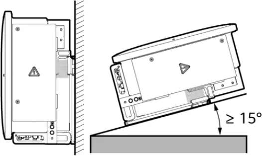
Angle
Clearance
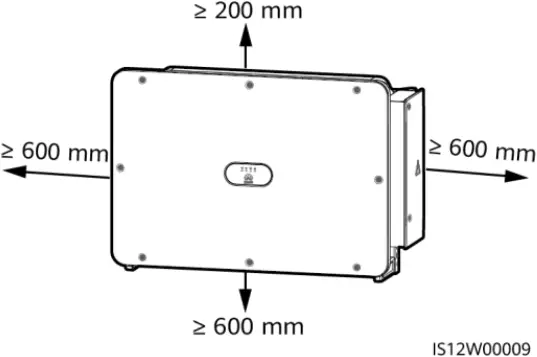
600-730 mm of clearance is recommended underneath.
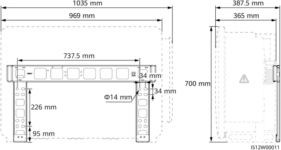
Dimensions
3 Installing a Solar Inverter
![]() NOTE
NOTE
- This quick guide describes how to install a solar inverter on a support. For details about wall-mounted installation, see the user manual.
- The M12x40 bolt assemblies are delivered with the solar inverter. If the bolt assembly length does not meet the installation requirements, prepare M12 bolt assemblies by yourself and use them together with the delivered M12 nuts.
- Before installing the mounting bracket, remove the security Torx wrench and set it aside.

- Position for binding the security Torx wrench
NOTICE
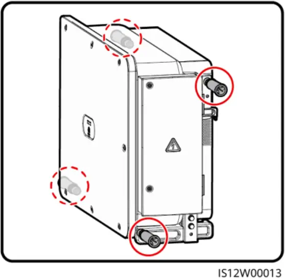
Use the handles to facilitate installation. Handles are optional and delivered separately. Ensure that the handles are securely installed. After the installation is complete, remove the handles and set them aside.
Installation Positions of Handles During Transportation
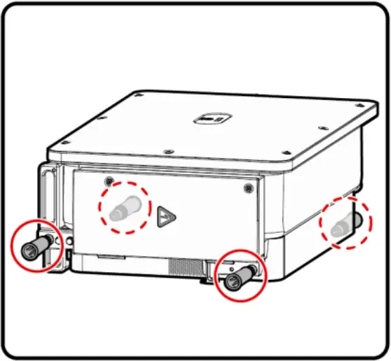
Installation Positions of Handles During Installation
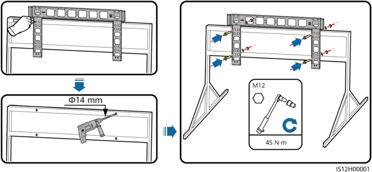
1. Install the mounting bracket.
![]() NOTE
NOTE
It is recommended that anti-rust measures be taken on the positions for drilling holes.
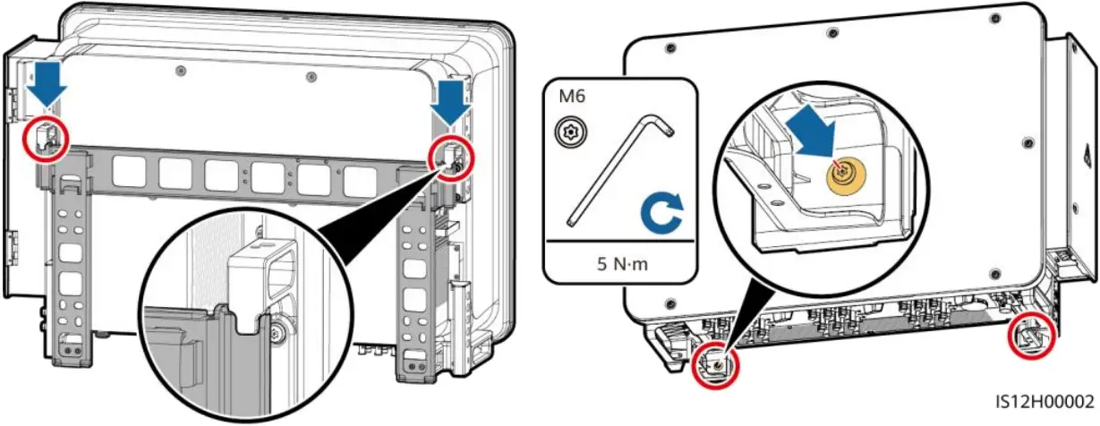
2. Install the solar inverter onto the mounting bracket. 3. Tighten security Torx screws.
4 Connecting Cables
NOTICE
- Connect cables in accordance with the local installation laws and regulations.
- To prevent poor cable connection due to overstress, leave enough slack before connecting the cables to the appropriate ports.
4.1 Preparations
![]() NOTE
NOTE
- S and Sp are the conductor cross-sectional areas of AC power cables and PE cables respectively.
- The cable size must comply with local cable standards.
- The factors that affect cable selection include the rated current, cable type, routing mode, ambient temperature, and maximum expected line loss.
Cable Description
| No. | Cable | Type | Conductor Cross-Sectional Area | Outer Diameter |
| 1 | PE cable[1] | Outdoor cable and M10 OT/DT terminals | Sp ≥ S/2 | – |
| 2 | Tracking system power cable | Three-core outdoor copper cable with dual-layer protection | 10 mm² | 15–18 mm |
| 3 | AC output power cable (multi-core) |
|
| 24–66 mm |
| AC output power cable (single-core) | You are advised to use a single-core outdoor cable and M12 OT/DT terminals. |
| 14–32 mm | |
| 4 | DC input power cable | PV cable that meets the 1100 V standard | 4–6 mm² | 5.5–9 mm |
| 5 | RS485 communications cable | Outdoor shielded twisted pair that meets the local standard and M4 OT/DT terminals. | 0.25–1 mm² |
|
| Note [1]: The value of Sp is valid only if the conductors of the PE cable and AC power cable use the same material. If the materials are different, ensure that the conductor of the PE cable with a proper cross-sectional area produces a conductance equivalent to that of the cable specified in the table. The specifications of the PE cable are subject to this table or calculated according to IEC 60364-5-54. | ||||
4.2 Installing a PE Cable
![]() NOTE
NOTE
- It is recommended that the PE cable of the solar inverter be connected to a nearby ground point. Connect the PE points of all solar inverters in the same array to ensure equipotential connections to PE cables.
- To enhance the corrosion resistance of a ground terminal, you are advised to apply silica gel or paint on it after connecting the PE cable.
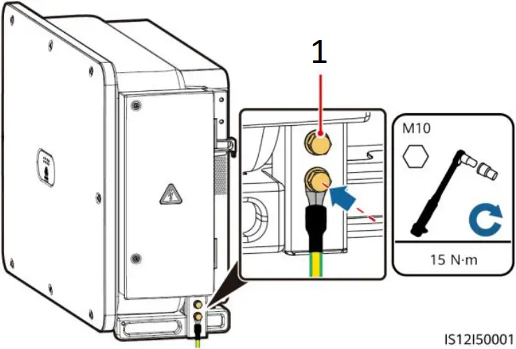
- Reserved PE point
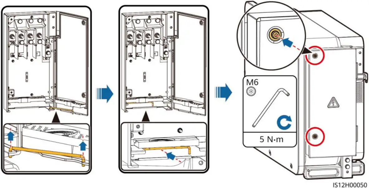
4.3 Opening the Maintenance Compartment Door
![]() WARNING
WARNING
- Do not open the panel of the solar inverter.
- Before opening the maintenance compartment door, turn off the downstream AC output switch and three DC switches at the bottom.
- Do not open the maintenance compartment door on rainy or snowy days. If you need to, take protective measures to prevent rain or snow from entering the maintenance compartment.
- Do not leave unused screws in the maintenance compartment.
1. Loosen the screws on the maintenance compartment door.
2. Open the maintenance compartment door and adjust the support bar.
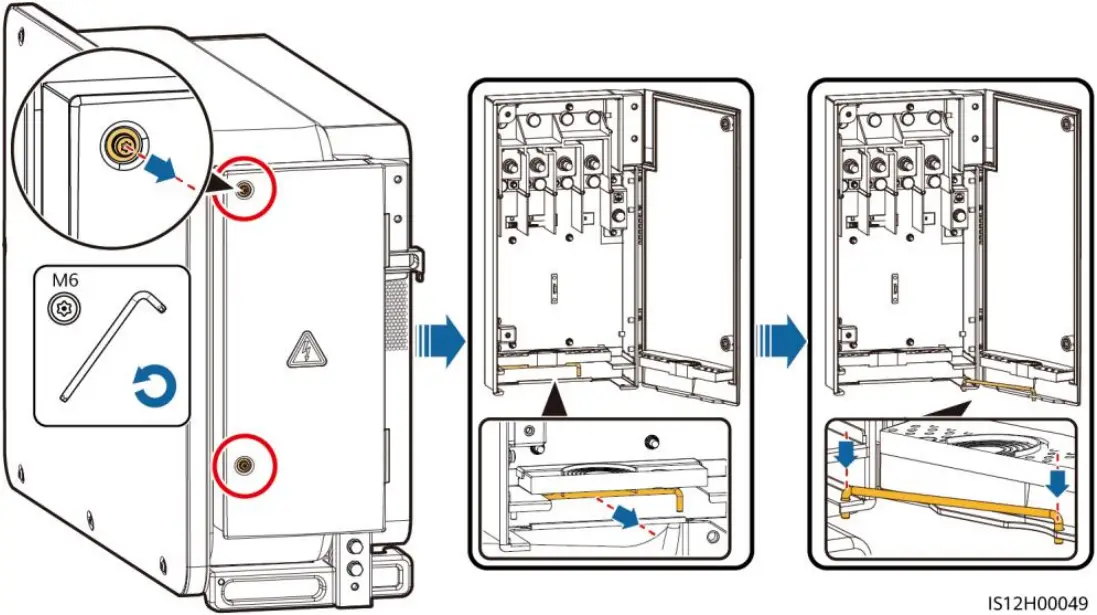
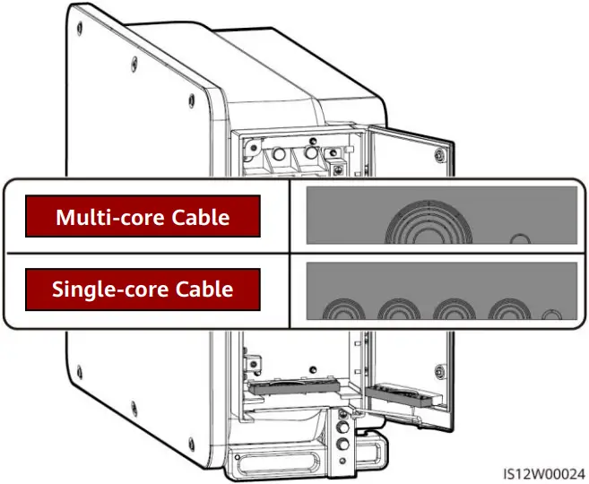
3. Remove the accessories and set them aside.
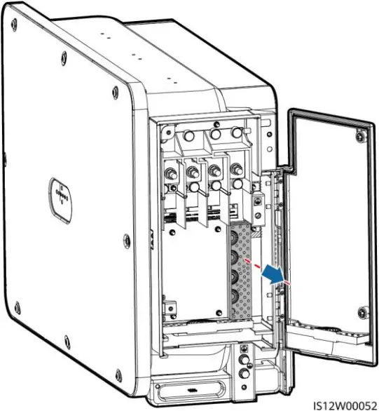
4. Select a crimping module according to the type of the AC output power cable.
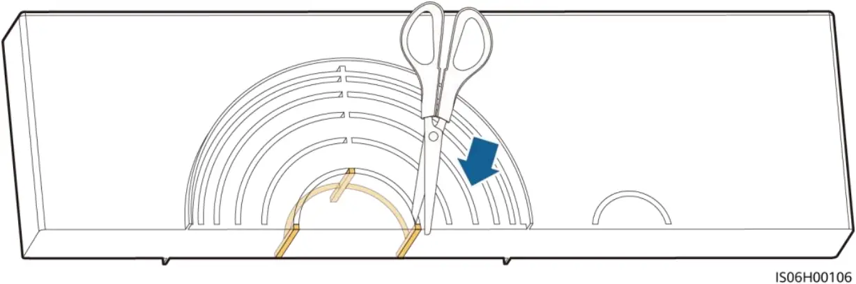
4.4 Removing the Rubber Rings from the Crimping Module
Use scissors to cut off the joints of the rubber rings to remove them. All rubber rings are removed in the same way.
NOTICE
Remove the corresponding rubber rings strictly according to the cable diameter range, and ensure that the crimping module is not damaged. Otherwise, the protection level of the solar inverter will be affected.
4.5 (Optional) Installing the Tracking System Power Cable
NOTICE
- The tracking system should be equipped with an overcurrent protective device or component. The length of the cable between the power cable terminal and the overcurrent protection device or component must be less than or equal to 2.5 m.
- The power supply of the tracking system should be an AC three-phase power grid.
- Keep flammable materials away from the power cable.
- The power cable must be protected with a conduit to prevent short circuits caused by insulation layer damage.
![]()
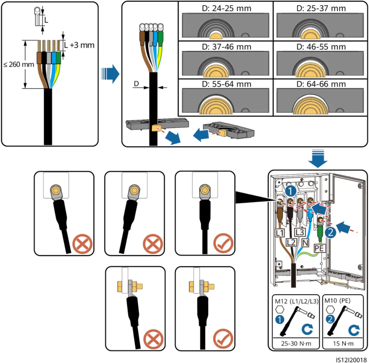
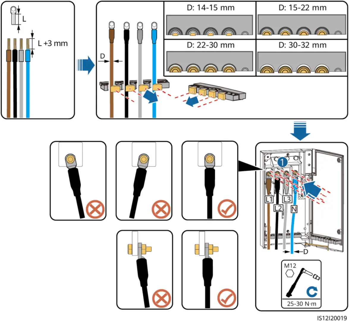
4.6 Installing the AC Output Power Cable
NOTICE
- The cable outer diameter can be measured using the ruler sticker in the maintenance compartment.
- Ensure that the AC output power cable is secured. Failure to do so may cause the solar inverter to malfunction or damage to its terminal block by issues such as overheating.
- Sufficient slack should be provided in the PE cable to ensure that the last cable bearing the force is the PE cable when the AC output power cable bears pulling force due to force majeure.
- If a screw on the maintenance compartment door is lost, obtain the spare screw from the fitting bag tied at the bottom of the maintenance compartment.
Multi-core Cable Connection Method
Single-core Cable Connection Method
Cable Connections
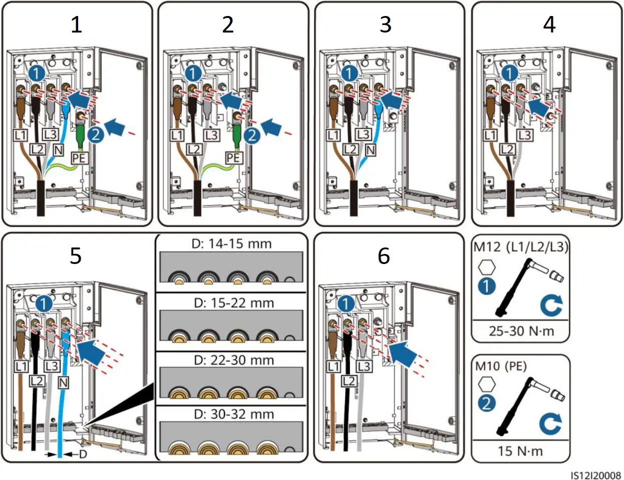
- Five-core cable
- Four-core cable
(including PE) - Four-core cable
(including N) - Three-core cable
- Single-core cable
(including N) - Single-core cable
(excluding N)
Closing the Maintenance Compartment Door
4.7 Installing DC Input Power Cables
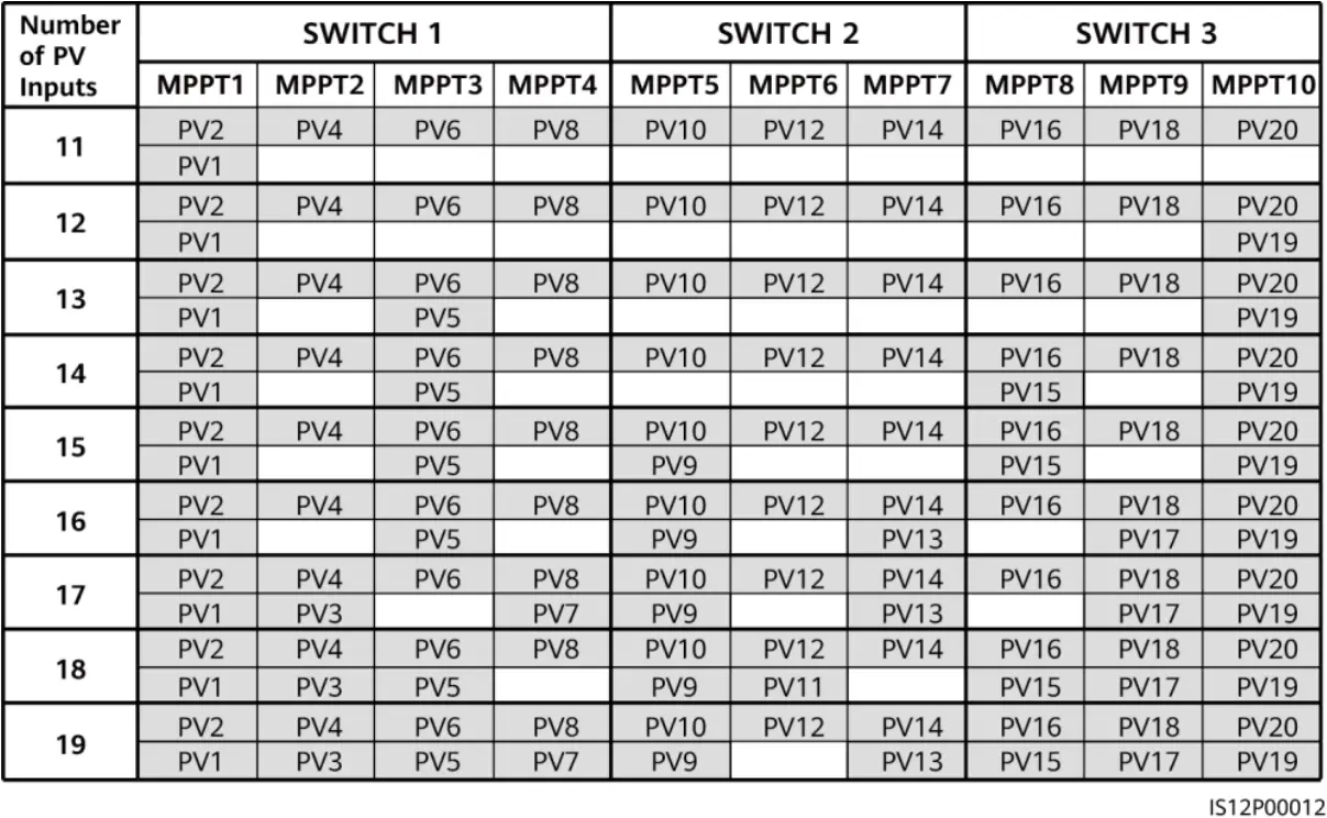
Selecting DC Input Terminals
![]() WARNING
WARNING
Ensure that the PV module output is well insulated to ground.
When the DC inputs are not fully configured, the DC input terminals must meet the following requirements:
- Evenly distribute the DC input power cables on the DC input terminals controlled by the three DC switches. DC SWITCH 1 is preferred.
- The even-numbered PV terminals are preferred to maximize the connections of MPPTs.
- If the number of PV inputs is 11 to 19, connect cables to the odd-numbered PV terminals from PV1 and PV19, and avoid connections to adjacent MPPTs if possible.
If the number of PV inputs is 11 to 19, the DC input terminals are selected as follows.
Installing DC Input Power Cables
NOTICE
- Use the positive and negative Amphenol Helios H4 metal contacts and DC connectors supplied with the solar inverter. Using incompatible positive and negative metal contacts and DC connectors may result in serious consequences. The caused device damage is not covered under any warranty.
- Before connecting the DC input power cables, label the cable polarities to ensure correct cable connections. Otherwise, the solar inverter may be damaged.
- Measure the voltage at the DC input end using a multimeter set to the DC position. If the voltage is a negative value, the DC input polarity is incorrect. Correct the polarity. If the voltage is greater than 1100 V, too many PV modules are configured to the same string. Remove some PV modules.
- If the DC input power cable is reversely connected and the DC switches are set to ON, do not perform any operation on the switches or the positive and negative connectors. Otherwise, the device may be damaged. The caused device damage is not covered under any warranty. Wait until the solar irradiance weakens at night and the PV string current decreases below 0.5 A. Set the three DC switches to OFF, and correct the connection of positive and negative connectors.
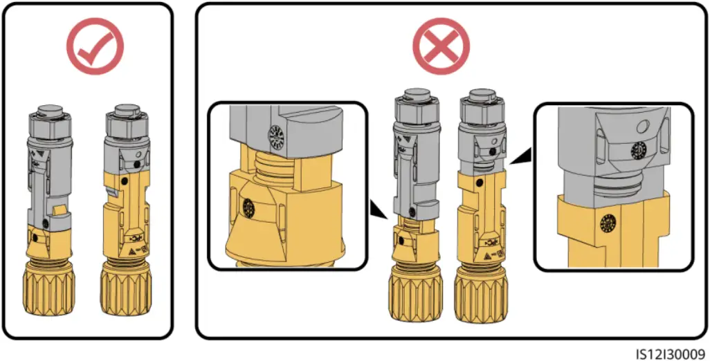
- Connect the PV string connector to the inverter connector, and then pull back the PV string connector along the axial direction to check whether the connectors are securely connected.
- The connector must be securely connected. Damages caused by improper connection are not covered under the warranty.
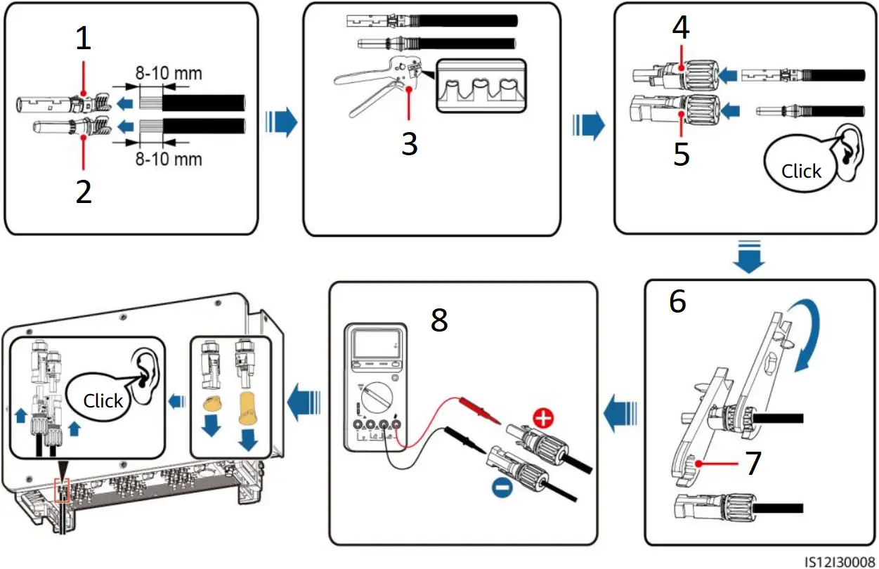
- Positive metal contact
- Negative metal contact
- H4TC0003 (Amphenol)
Ensure that the cable cannot be pulled out after being crimped. - Positive connector
- Negative connector
- Ensure that the locking nut is secured.
- H4TW0001
(Amphenol) - Use a multimeter set to the DC position to measure the DC voltage. (DC voltage: ≤ 1100 V)
Connector connection:
4.8 Installing RS485 Communications Cables
NOTICE
- The solar inverter supports RS485 communication and MBUS communication. If the MBUS communication mode is used, you do not need to connect the communications cable to the RS485-1 port.
- This section describes how to connect three communications cables.
- When routing communications cables, separate communications cables from power cables to prevent communication from being affected.
Pin Definitions of Communications Ports
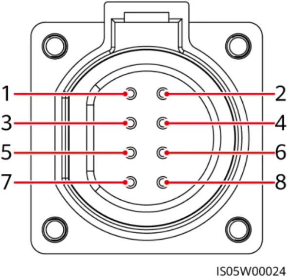
| Port | Pin | Definition | Pin | Definition | Description |
| RS485-1 | 1 | RS485A IN, RS485 differential signal+ | 2 | RS485A OUT, RS485 differential signal+ | Used for cascading solar inverters or connecting to devices such as the SmartLogger. |
| 3 | RS485B IN, RS485 differential signal– | 4 | RS485B OUT, RS485 differential signal– | ||
| Protection ground | 5 | PE, shielding ground | 6 | PE, shielding ground | – |
| RS485-2 | 7 | RS485A, RS485 differential signal+ | 8 | RS485B, RS485 differential signal– | Used for connecting to RS485 slave devices. |
Connecting RS485 Communications Cables (4-8 mm Four-hole Rubber Plug)
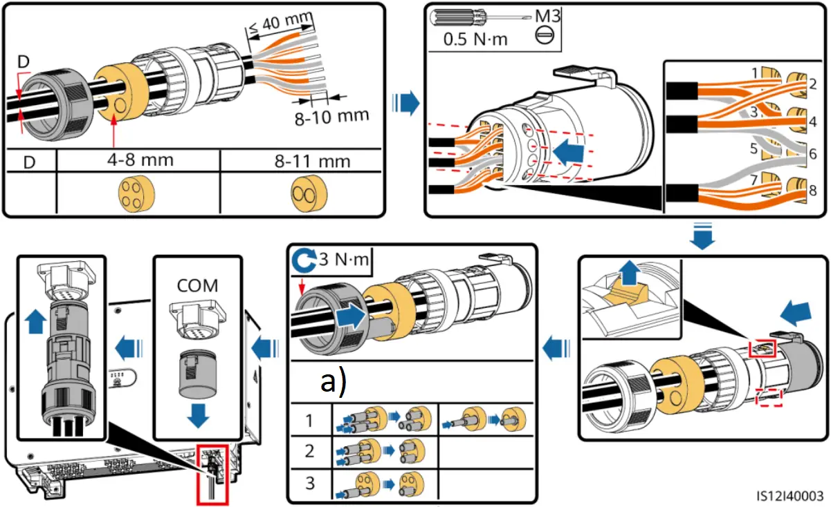
a) Number of communications cables
Connecting RS485 Communications Cables (4-8 mm Two-hole or Three-hole Rubber Plug)
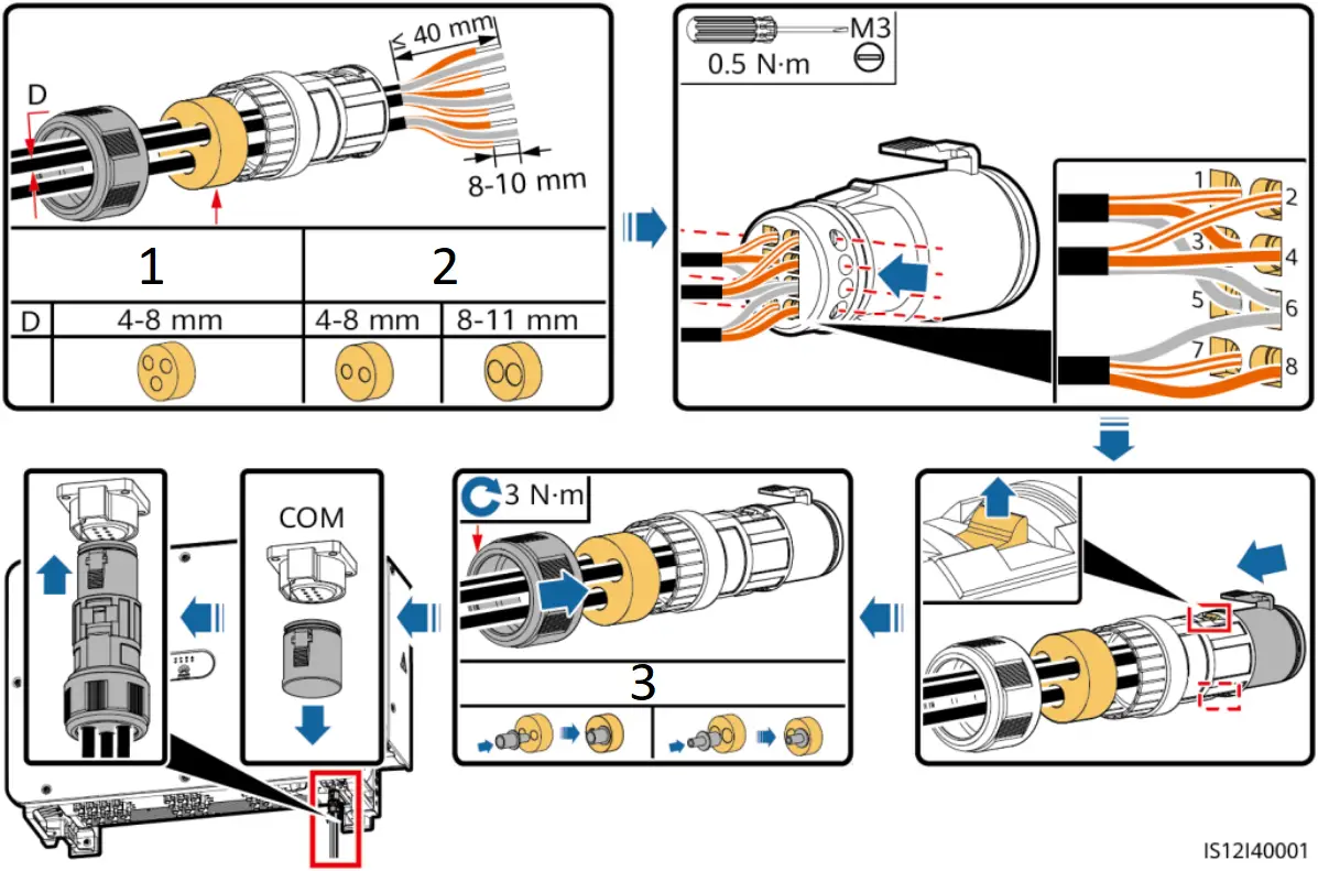
- Three communications cables
- One or two communications cables
- One communications cable
5 Verifying the Installation
| No. | Acceptance Criteria |
| 1 | The solar inverter is installed correctly and securely. |
| 2 | The DC switches and downstream AC switch are set to OFF. |
| 3 | All cables are connected correctly and securely. |
| 4 | The installation space is proper, and the installation environment is clean and tidy. |
| 5 | The maintenance compartment door is closed and the screws are secured. |
| 6 | Unused DC input terminals are sealed. |
| 7 | Unused USB ports are plugged with watertight caps. |
6 Powering On the System
![]() WARNING
WARNING
When LED2 is steady green (meaning that the inverter is grid-tied), do not turn on any DC switch. Otherwise, the inverter may be damaged because the insulation resistance is not detected.
NOTICE
- Before turning on the AC switch between the solar inverter and the power grid, check that the AC voltage is within the specified range using a multimeter set to the AC position.
- Do not turn the DC switch to the unloaded position
 .
.
- Turn on the AC switch between the solar inverter and the power grid.
- Set DC SWITCH 1 (MAIN SWITCH) at the bottom of the solar inverter chassis to ON. When you hear a click, the switch is ON.
- Check the status of the PV connection indicator. If it is steady green, set DC SWITCH 2 and DC SWITCH 3 to ON.
- Observe the LED indicators to check the operating status of the solar inverter.
| Indicator | Status (Blinking Fast: On for 0.2s and Off for 0.2s; Blinking Slowly: On for 1s and Off for 1s) | Description | |
| PV connection indicator
| Steady green | At least one PV string is properly connected, and the DC input voltage of the corresponding MPPT circuit is at least 200 V. | |
| Blinking green fast | If the alarm/maintenance indicator is red, an environmental fault at the DC side of the solar inverter is generated. | ||
| Off | The solar inverter disconnects from all PV strings, or the DC input voltage of all MPPT circuits is less than 200 V. | ||
| Grid connection indicator
| Steady green | The solar inverter is in grid-tied mode. | |
| Blinking green fast | If the alarm/maintenance indicator is red, an environmental fault at the AC side of the solar inverter is generated. | ||
| Off | The solar inverter is not in grid-tied mode. | ||
| Communications indicator
| Blinking green fast | The solar inverter receives communication data normally. | |
| Off | The solar inverter has not received communication data for 10 seconds. | ||
| Alarm/ Maintenance indicator
| Alarm status | Steady red | A major alarm is generated.
|
| Blinking red fast | A minor alarm is generated. | ||
| Blinking red slowly | A warning alarm is generated. | ||
| Local maintenance status | Steady green | Local maintenance succeeds. | |
| Blinking green fast | Local maintenance fails. | ||
| Blinking green slowly | The solar inverter is in local maintenance or shuts down over a command. | ||


7 Commissioning
![]() NOTE
NOTE
- The FusionSolar app is recommended when the solar inverter is connected to the FusionSolar smart PV management system. The SUN2000 app is recommended when the solar inverter is connected to other management systems.
- The FusionSolar app or SUN2000 app communicates with the solar inverter through the WLAN module, Bluetooth module, or USB data cable to provide functions such as alarm query, parameter settings, and routine maintenance.
- Access the Huawei app store (https://appstore.huawei.com), search for FusionSolar or SUN2000, and download the app installation package. You can also scan the QR codes below to download the apps.

FusionSolar App SUN2000 App
NOTICE
- The screenshots are for reference only. The actual screens may vary.
- When the WLAN connection is used, the initial name of the WLAN hotspot is Adapter-WLAN module SN, and the initial password is Changeme.
- When you log in to the system for the first time, set the login password. To ensure account security, protect the password by changing it periodically, and keep it secure. Your password might be stolen or cracked if it is left unchanged for extended periods. If a password is lost, devices cannot be accessed. In these cases, the Company shall not be liable for any loss caused to the plant.
- Set the correct grid code based on the application area and scenario of the solar inverter.
Scenario in Which Solar Inverters Are Connected to the FusionSolar Smart PV Management System
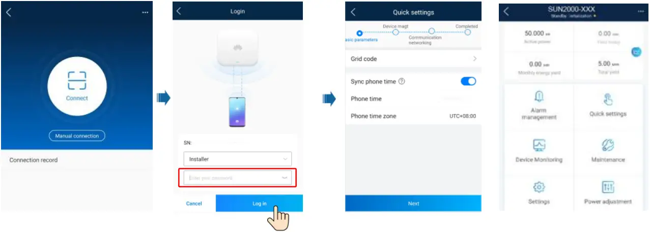
- Open the FusionSolar app, log in to intl.fusionsolar.huawei.com using an installer account, and choose Me > Device commissioning. Then, scan the QR code on the WLAN module or the bar code on the Bluetooth module, or manually connect to the device via the WLAN hotspot, Bluetooth, or USB port to access the device commissioning screen.
- Enter the login password.
- Tap Log in and go to the Quick Settings screen or the solar inverter screen.
Scenario in Which Solar Inverters Are Connected to Other Management Systems
- Open the SUN2000 app, scan the QR code on the WLAN module or the bar code on the Bluetooth module, or manually connect to the device via the WLAN hotspot, Bluetooth, or USB port to access the device commissioning screen.
- Enter the login password.
- Tap Log in and go to the Quick Settings screen or the solar inverter screen.
Huawei Technologies Co., Ltd.
Huawei Industrial Base, Bantian, Longgang
Shenzhen 518129 People’s Republic of China
solar.huawei.com


