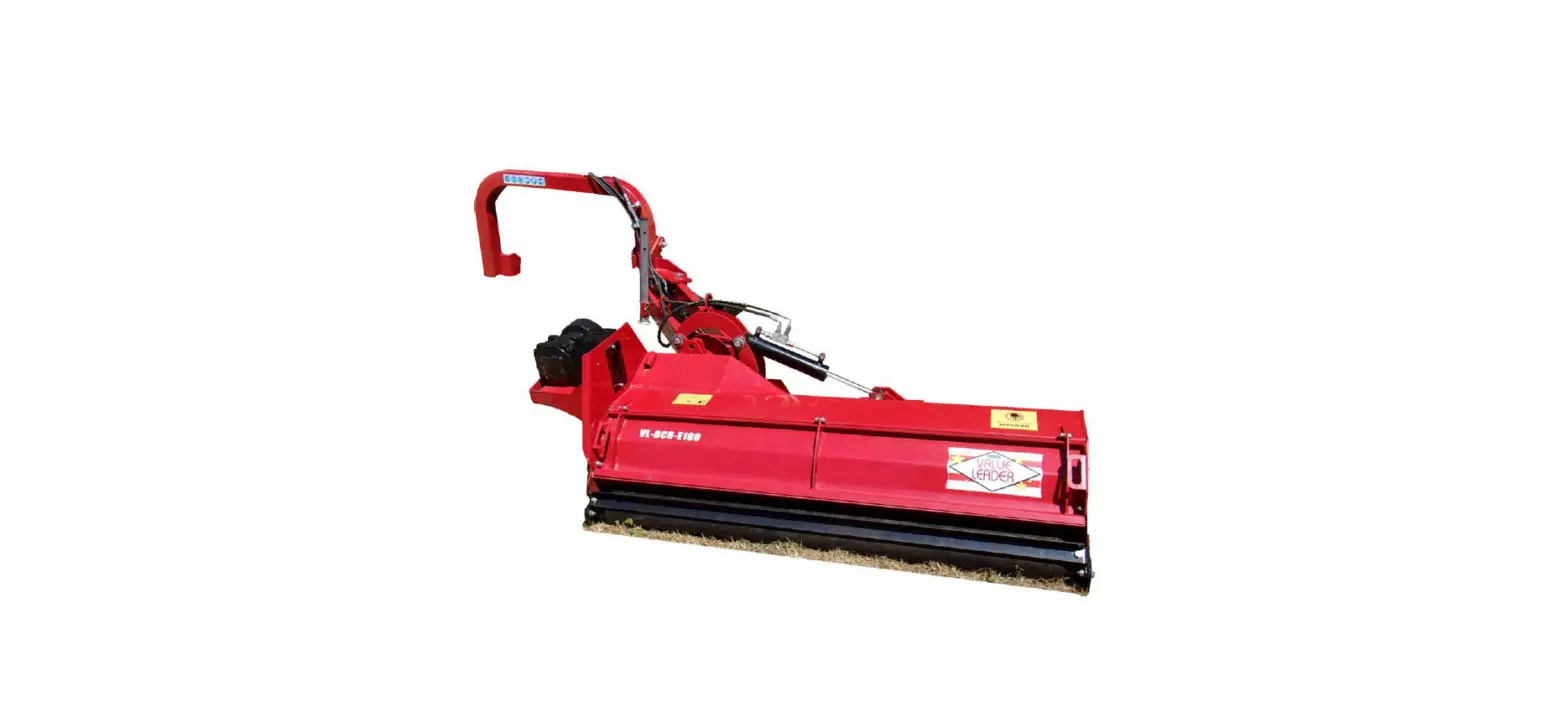
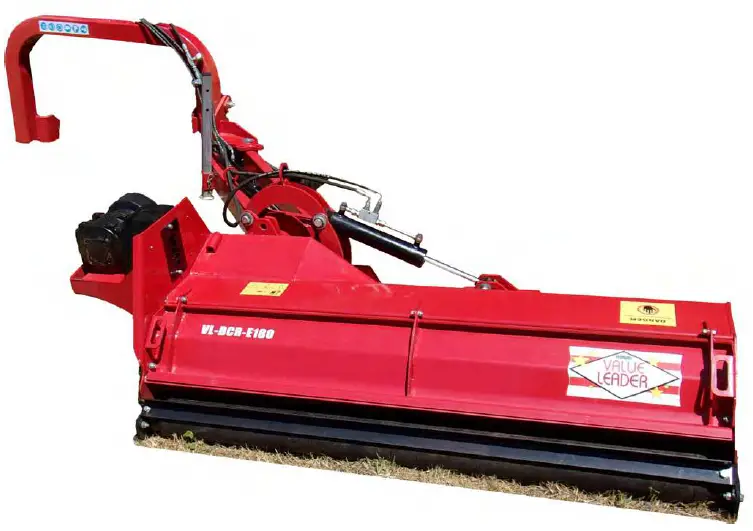
BETSTCO BCR Series 63 Inch Heavy Duty Ditch Bank Flail Mower
Product Information
The BCR SERIES is a machine designed for use with compact tractors and is available in three models: BCR-140, BCR-160, and BCR-180. The machine is suited to tractors with an engine horsepower range of 40-75 HP and is compatible with Category 1 & 2 3-point linkages. The machine has a working width of 4’6″ to 5’10”, depending on the model, and weighs between 1100 lbs and 1500 lbs. The machine has a gearbox and operates at 540 rpm.
The product is manufactured by Betstco and can be purchased from their website, www.betstco.com. For more information or assistance, customers can contact Betstco on 541-895-3083 between Monday to Friday, 7 am-4 pm PST.
Product Usage Instructions
- Ensure all potential operators read the manual thoroughly before using the machine.
- Ensure the tractor and machine are stopped and keys are out of the ignition before set-up/maintenance.
- Do not modify equipment in any way that may impair the operation or overall safety of the machine.
- Use only compact tractors within the power range specified.
- Do not use machinery to transport personnel or livestock.
- When traveling on the road/public places, always keep the PTO turned off.
- Always keep the machine maintained and in good condition. Where necessary, repair or replace any defective parts. Do not modify the machine.
- Pay attention to the sharp/pointed parts while servicing the machine.
- All protective parts should be in good condition before operating machinery.
- Keep all safety signs clean and legible. Replace any which are missing or illegible. If a component with safety sign/(s) is replaced, make sure new safety sign/(s) are attached in the same locations.
- Machinery and PTO should be operated at the recommended speed at all times.
- Familiarize yourself with various safety signs, the type of warning, and the area, or particular function related to that area for good safety awareness.
- Never consume alcohol or drugs while operating the machine. Consult your doctor about using this machine while taking prescription medications.
Before using the machine, conduct the following checks:
- On receipt of your new machine and again within the first 4 hours of use, check over the machine.
- Conduct tractor pre-use checks, running/operating checks, and post-use regular checks.
For installation and set up:
- Ensure the tractor and machine are stopped and keys are out of the ignition before set up/maintenance.
General Safety Information
Ensure all potential operators read this manual thoroughly before using the machine
- Safety: Ensure tractor and machine is stopped & keys out of the ignition before set-up/maintenance
- Safety: Failure to follow good safety standards could result in severe injury or even death
- Misuse: This machine is designed for use with compact tractors, and should be used only for the indicated purpose. We does not take responsibility if the machine is used for any otne purpose. Children must not operate the machine under any circumstance.
- Modification: Do not modify equipment in any way. This may impair the operation and overal safety of the machine.
- Tractor requirements: Use only compact tractors within the power range specified.
- Misuse transport: Do not use machinery to transport personnel or livestock.
- Condition: For the safety of personnel and the optimum performance of the machine, you should check the condition of the machine and the tractor before starting. Before use check all nuts and bolts are tight.
- Spacial awareness: Always check the operating area is safe before starting machinery. Operator clothing: The operator should not wear loose clothing while operating machinery. Safety wear: Always use appropriate ear protection when running a tractor and machinery Ensure you are wearing protective gloves when servicing and using machinery.
- Bystander safety: Ensure bystanders keep away from the machine when it is in use. Do not touch moving parts when the machine is at work.
- Public places: When traveling on the road/in public places, always keep the PTO turned on
- Maintenance: Always keep the machine maintained and in a good state. Where necessary repair or replace any defective parts. Do not modify the machine.
- Sharp objects: Pay attention to the sharp/pointed parts while servicing the machine.
- Safety guards: All protective parts should be in good condition before operating machinery.
- Safety signs/stickers: Keep all safety signs clean and legible. Replace any which are missing or illegible. If a component with safety sign/(s) is replaced, make sure new safety sign/(s) are attached in the same locations.
- Operating speeds: Machinery and PTO should be operated at the recommended speed at all times.
- Safety awareness: Good safety requires that you familiarise yourself with various safety signs,
the type of warning, and the area, or particular function related to that area. - Alertness: Never consume alcohol or drugs these can hinder alertness/coordination. Consult your doctor about using this machine while taking prescription medications.
Machinery Pre-Use Checks
On receipt of your new machine and again within the frt 4 hours of use, or the’shake in’ period as we like to call it, we always recommend checking over the machine.
- Check all bolts, Nuts, and Screws are light on the unit.
- Tighten/Check any bolts and nuts securing blades.
- If your machine has belts, check the tension and adjust if required.
- Apply grease to grease points if necessary.
- Check gear oil level. Do not overfill
Tractor Pre-Use Checks
- Check that the machine is properly attached to the tractor. Ensure that secure pins are used on the linkage mounting pins.
- Be sure to add extra weights to the front of the tractor or add wheel weights if required.
- Check that the tractor’s PTO shaft turns freely and that the machine’s PTO drive shaft can extend easily. Grease the PTO drive sha using the grease points.
- The chain on the PTO shaft should be checked and in good condition. The universal joints installed should be in a good state with proper protective parts.
- Before installing the PTO shaft, the tractor and machine should be stopped, and remove the key.
- Install and secure all safety guards, doors, and covers before starting
- Bystanders should leave the immediate area before connecting the drive from the tractor.
Running/Operating Checks
- Always keep the PTO output from the tractor at 540 RPM when running machinery.
Post-Use Regular Checks
- Check blades, belts and wearing parts. Be sure they are not damaged and blades swing freely in their mount. Repair or replace as required.
- Clean machinery and check for/clear any entangled material which may have got stuck around any rotating parts.
Specifications
| Specifications | BCR-140 | BCR-160 | BCR-180 |
| Suited to Engine HP | 40-70 HP Tractors | 50-75 HP Tractors | 50-75 HP Tractors |
| 3-Point Linkage | Cat. 1 & 2 | Cat. 1 & 2 | Cat. 1 & 2 |
| Length | 5’11” | 6’3” | 6’7” |
| Width | 7’8” | 7’8” | 7’8” |
| Height | 3’4” | 3’4” | 3’4” |
| Weight | 1100lbs | 1300lbs | 1500lbs |
| Gearbox | 50hp | 50hp | 50hp |
| Working Width | 4’6” | 5’2” | 5’10” |
| PTO | 540rpm | 540rpm | 540rpm |
Installation & Set Up
- Safety: Ensure the tractor and machine are stopped and the key is out of the ignition before set up/maintenance.
- Safety: Make sure the PTO drive isn’t connected at any point until instructed to do so.
Attaching The Mower
Start by finding a flat piece of ground. Lower the three-point linkage on your tractor to its lowest position and attach the mower to the tractor using the three-point linkage
pins and linchpins. Attach the hydraulic connections [seesection on hydraulic fing & operaon]. Then, with the rear roller on the mower on the ground, adjust the length of the top link arm and use the tractor hydraulics to ensure the skids at the side of the flail mower are parallel with the ground when horizontal.
By hand, rotate the blade rotor so that a row of blades hang vertically towards the ground to give an idea of the cutting height. Check the clearance between the bottom
of the blades and the ground, this should be at least 2 inches. The cutting height can be set for longer grass by simply raising the hydraulic lift arms on your tractor or/and by adjusting the rear roller and skids on the machine to increase or decrease the blade clearance as required [ see the section on adjusting the cutting height].
The working speed of the machine should always be at a walking pace, depending on the working conditions. Overgrown grass and weeds should be cut at a much slower pace for the best cut and to avoid any damage to the mower. Check your PTO’s shaft’s grease points and apply grease if needed. Then attach the PTO shaft and ensure the locking pin is secured on both the tractor and mower. Attach
the chain to a secure point on the tractor/implement
Pre-Mowing Checklist
Before starting the machine, always check and adjust the following:
- Hydraulics and fitted and operated correctly
- Set the correct cutting height
- Tension of the belt drive
- Oil Level of the gearbox
- Lubrication/Grease Points
- Tighten all bolts, nuts, and screws.
- All protective guards are in place and storage stands are removed.
Operating Advice
- Safety: Ensure the tractor and machine is stopped and the key is out of the ignition before set up/maintenance.
- Safety: Before attaching/detaching machinery ensure the hydraulic lift system is in a neutral position
Hydraulic Fitting & Operation
Always check your tractor’s operating manual for the recommended type of hydraulic fluid for your specific tractor. This should also give an idea of the tractors’ reservoir capacity and how to check the level of fluid. Always check your tractor’s hydraulic reservoir is topped before using any hydraulically operated machinery. Your tractor will fill the pipes and RAMs with the hydraulic fluid on first use. So it is always best to check the hydraulic fluid reservoir after your first connection as well.
Start by setting the hydraulic lever on your tractor into a position to release the hydraulic pressure. Connect the hydraulic hoses from the machine to the tractor using the quick-release couplings. Start your tractor and activate the hydraulics to test the connection. Check to see if there is any leaks from the tractor or the implement.
Never suddenly change the direction of hydraulic flow/the direction of the machine as this may cause excess pressure and damage to the machine/tractor. Before disconnecting always stop the engine and move the hydraulic control levers backward and forwards to release any pressure One pair pf hoses operate the tilt function on the cutting head. The second pair operate the offset reach of the cutting head. It is key to get to grips with both before any cutting is started.
Tilt Adjustment
The mower heads can be moved up to vertically for cutting low hedgerows (+90 degrees), and set horizontally for general paddock mowing (0 or moved downwards to -50 degrees). These measurements are for indication and may require a degree of adjustment on the tractor’s lower linkage arms to achieve.
Cutting Height Adjustment
Safety:
Ensure the tractor and machine is stopped and the key is out of the ignition before set up/maintenance.
Note:
Clearance of blades to the ground should be at least 2 inches and higher on uneven ground Getting the cutting height right is the key to creating the best cut and finish when mowing. This needs to be adjusted to the way of the land and also the length of the grass and the density of the weeds.
The cutting height can be set for longer grass by simply raising the hydraulic lift arms on your tractor or/ and by adjusting the rear roller and the skids on the machine.
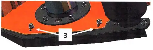
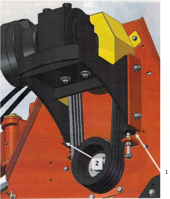
Roller Adjustment
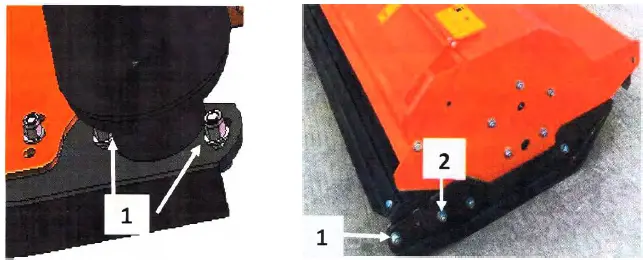
- Remove bolt/bolt 1 on both sides of the machine to adjust to the desired height.
- Adjust the roller by aligning the selected holes in the roller support holes at position 2 (using the hole closest to the ground gives the highest working height).
- Put bolt 1 into selected hole/hole 2 and re-tighten bolt/bolt 1.

- Remove the nuts and bolts 3 on the skids front & back of both sides of the machine
- Move the skids up or down to the desired height with the set holes on the skids
- Re-fit nuts and bolts 3.
Adjusting Belt Tension
- Safety: Ensure the tractor and machine are stopped and the key is out of the ignition before set up/maintenance.
Correct Belt Tension
The correct belt tension is achieved when the belt can be deflected by the belt thickness of about 3/8 at the center point between the pulleys. Tension should be checked regularly. A generic measure across machines is the belt should be able to twist a quarter turn by hand, any more and they are too loose and any less are too tight. You may run the risk of losing the drive to the mower or burning the belts prematurely
Belt Tension
Safety:
Ensure the tractor and machine are stopped and the key is out of the ignition before set up/maintenance.
- Remove the belt cover.
- Loosen four bolts securing the gearbox to the mounting plate.
- Loosen bolts behind the belt cover holding the support shaft.
- loosen off the counter locking nuts 3.
- Adjust belt tension by adjusting the height of the counter nuts 3.
- Align the gearbox ensuring the drive shaft is parallel with the body and re-tighten the nuts.
- Re-tighten all bolts.
- Replace the belt cover.
Gear Oil Change and Check
Safety:
Ensure the tractor and machine are stopped and the key is out of the ignition before set up/maintenance.
Always check the oil when the machine has cooled down and on a level surface. Make sure bolts are tightened correctly. The filler/level plug should be secure but not over-lightened.
Important Information
| Gear Oil Grade | 80w90 Gear Oil for All Conditions |
| Gearbox Oil Level | Approx. 0.5 Litres to Half Full |
| Level/Drain Plug Size | 8mm Allen Key |
| First Oil Change | 50 Hours Use |
| Oil Change Frequency | 250 Hours/Yearly |
Safety:
Ensure the tractor and machine is stopped and the key is out of the ignition before set up/maintenance.
| Grease Type | Multi-Purpose Lithium Based Grease |
| Grease Frequency | Check Every 4-8 Hours (Top off if Need) |
Greasing & Lubrication Points
- Bearings on the blade rotor x2
- Bearings on the rear roller x2
- PTO shaft x2
- Body arm x4
- Hydraulic ram x2
Wipe grease nipples with a clean cloth before greasing to avoid injecting any dirt and grit. Press grease into each nipple three to five times. We recommend using a hand-held grease gun for best results. If the grease nipples will not take grease, remove and clean them thoroughly. Also, clean the lubricant passageway. If you notice any grease points are broken, replace or repair them immediately.
Other Maintenance
- Blades: Check the condition of the blades and replace them if worn or broken. Always be aware while handling blades, wear gloves, and use suitable tools for changing blades.
- Belts: Check the condition of belts, if worn or frayed, replace them. Adjust tension if needed.
- Oils: Ensure oil levels are checked and topped up when needed. Replace any oils per schedule.
- PTO Shaft: Check the condition of your PTO shaft and replace if worn or damaged immediately.
- Cleaning: Ensure the mower deck and blades are cleaned of mud and grass. Remove debris from moving parts. DO NOT spray bearings when cleaning with a high-pressure washer.
- Bearings: Check the bearings on the blade roller and the rear roller. If the oil seals are damaged, debris may enter the bearings. Clean or replace if necessary. Run the mower without a load for 3-5 minutes to check bearings are operating smoothly.
- Paintwork: Re-coat any damaged paintwork to prevent corrosion.
- Skids: Check the condition of the kids and replace if worn.
Parts Diagram & List
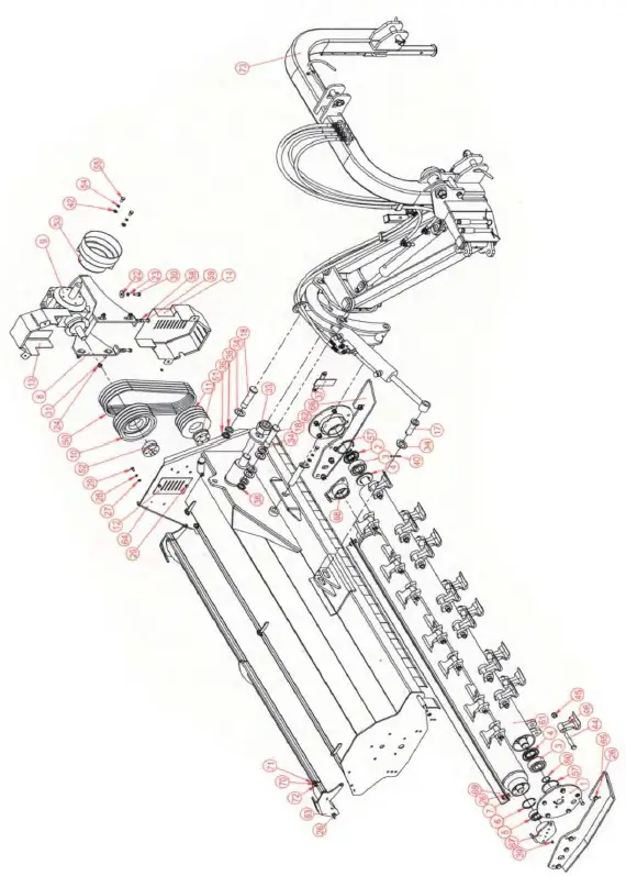
| NO. | PART # | NAME & SPECIFICATION | QTY. | REMARK |
| 1 | BCRI200.032 | Bearing Block (right) | 1 | |
| 2 | TC40X85X10 | Oil Seal | 1 | |
| 3 | GB T 281-94 | Self-aligning Bearing 2308 | 2 | |
| 4 | TC50X90X10 | Oil Seal | 2 | |
| 5 | GBT.281-94 | Self-aligning Beraing 2207 | 2 | |
| 6 | GB 893. 1-86 | Circlip for hole 72 | 2 | |
| 7 | BCRI200.016 | Roller | 1 | |
| 8 | BCRI200.020 | Bracket for Gearbox | 1 | |
| 9 | XH50.003Z. 03W | Gearbox | 1 | |
| 10 | BCS170.105 | Driving Pulley | 1 | |
| 11 | BCCS170.106 | Driven Pulley | 1 | |
| 12 | BCRI200.107 | Plate | 1 | |
| 13 | BCRI200.021 | Belt Cover up | 1 | |
| 14 | BCRI200.022 | Belt Cover down | 1 | |
| 15 | BCRI200.023 | Round Pin | 1 | |
| 16 | BCRI200.024 | Pin 1 | 1 | |
| 17 | BCRI200.025 | Pin 2 | 1 | |
| 18 | BCRI200.119 | Lifting Pin | 2 | |
| 19 | LG180.104 | Up Linkage Pin | 1 | |
| 20 | GB97.1-85/12 | Plain Washer 12 | 34 | |
| 21 | GB97.1-85/14 | Plain Washer 14 | 10 | |
| 22 | GBT96.2-2002 | Plain Washer 12×3 | 4 | |
| 23 | GB93-12 | Spring Washer 12 | 4 | |
| 24 | GB6170-86-12LN | Lock Nut M12 | 20 | |
| 25 | GB6184-86/14 | Lock Nut M14 | 6 | |
| 26 | GB5783-M12X35 | Bolt M12x35 | 18 | |
| 27 | GB/T95-2002 | Plain Washer | 6 | |
| 28 | GB93-8 | Spring Washer 8 | 5 |
| NO. | PART # | NAME & SPECIFICATION | QTY. | REMARK |
| 29 | GB5783-86/8X16 | Bolt M8x16 | 6 | |
| 30 | GB5783-M12X30 | Bolt M12x30 | 4 | |
| 31 | GBT.794-93 | Step Bolt M12x45 | 4 | |
| 32 | BCRI200.104 | Lifting Flap | 1 | |
| 33 | GB6184-86 | Lock Nut M42 | 1 | |
| 34 | GB/T95-2002 | Plain Washer 30 | 6 | |
| 35 | GB5783-86/8X16 | Spring Washer 30 | 2 | |
| 36 | GB810-88/30X1.5 | Round Nut M30 | 2 | |
| 37 | BCRI200.026 | T PLate | 1 | |
| 38 | 011 | Lock Pin | 1 | |
| 39 | M10X1 | Grease Zerk | 3 | |
| 40 | GB/T91-2000 | Cotter 5×50 | 1 | |
| 41 | GB/T91-2000 | Cotter 3.2×25 | 2 | |
| 42 | GB/T97.1-2002 | Plain Washer 10×2 | 8 | |
| 43 | M8X1 | Grease Zerk | 1 | |
| 44 | GB/M16X85 | Bolt M16x85 | 28 | |
| 45 | GB889.1-M16 | Lock Nut M16 | 28 | |
| 46 | H.3 1/8 | Hammer Blade | Qty’s Below | |
| 47 | EF175-108 | Flap | 23 | |
| 48 | EF175-108A | Flap | 4 | |
| 49 | EF175-109 | Flap | 1 | |
| 50 | BX1295.4 | Belt | 4 | |
| 51 | 26-40.80 | Power Lock | 4 | |
| 52 | 26-33.80 | Power Lock | 20 | |
| 53 | EF175-123 | Dust Cover | 6 | |
| 54 | GB/T93-1987-10 | Spring Washer 10 | 3 | |
| 55 | GB/T5783/10X20 | Bolt M10x20 | 3 | |
| 56 | GB5783-M14X40 | Bolt M14x40 | 4 |
| NO. | PART # | NAME & SPECIFICATION | QTY. | REMARK |
| 57 | GB893. 1-86/90 | Circlip for hole 90 | 4 | |
| 58 | GB6170-M12 | Nut M12 | 4 | |
| 59 | GB5783-86/12X80 | Bolt M12x80 | 2 | |
| 60 | GB 894.1-86 | Circlip for hole 40 | 1 | |
| 61 | BCRI200.030 | Blade Axel | 1 | |
| 62 | BCRI200.031 | Bearing Block left | 1 | |
| 63 | BCRI200.060 | Opening Rear Deck | 1 | |
| 64 | BCRI200.015A | Deck Weldment | 1 | |
| 65 | BCRI200.018 | Adjustment Plate R | 1 | |
| 66 | BCRI200.019 | Adjustment Plate L | 1 | |
| 67 | BCRI200.017 | Roller Bearing Block L | 1 | |
| 68 | BCRI200.018 | Roller Bearing Block R | 1 | |
| 69 | BCRI200A.201 | Scraper | 1 | |
| 70 | GB889-86/M10 | Lock Nut M10 | 3 | |
| 71 | GB97.1-10 | Plain Washer 10 | 3 | |
| 72 | GB/T5783/10X30 | Bolt M10x30 | 3 | |
| 73 | BCR200.003 | 3-Point Linkage | 1 | |
| Hammer Blades for BCR | ||||
| BCR 140 | 16 | |||
| BCR 160 | 20 | |||
| BCR 180 | 24 |
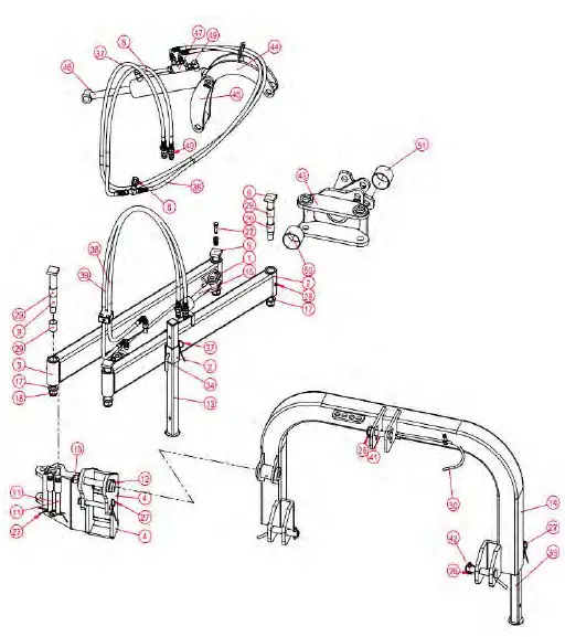
| NO. | PART # | NAME & SPECIFACATION | QTY. | REMARK |
| 1 | BCRI200.051 | Connected pin for Cylinder | 2 | |
| 2 | BCRI200.050 | Connected Tube R | 1 | |
| 3 | BCRI200.049 | Connected Tube L | 1 | |
| 4 | BCRI200.048 | Lifting Frame | 1 | |
| 5 | BS/A21.50(G1/2) | Bonded Washer | 4 | |
| 6 | STU-G1/4 | Throttle Valve | 1 | |
| 7 | BS/A13.70(G1/4) | Bonded Washer | 7 | |
| 8 | BCRI200.044 | Lifting Inlet Pipe | 1 | |
| 9 | BCRI200.040 | Long Pin Weldment | 4 | |
| 10 | BCRI200.124 | Protected Pin 1 | 1 | |
| 11 | BCRI200.127 | Protected Pin 2 | 2 | |
| 12 | BCRI200.053 | Short Pin Weldment | 1 | |
| 13 | BCRI200.054 | Arm-Brace Weldment | 1 | |
| 14 | BCRI200.047 | Lifting Frame Weldment | 1 | |
| 15 | BCRI200.052 | Swing Cylinder | 1 | |
| 16 | BCR140.200 | Pipe Clamp | 1 | |
| 17 | GB97.1-85/14 | Plain Washer 24×4 | 5 | |
| 18 | GB889.1-M24 | Lock Nut M24 | 5 | |
| 19 | GB97.1-85/12 | Plain Washer 12 | 4 | |
| 20 | BCRI200.125 | Spring Leaf | 1 | |
| 21 | GBT889.1-M12 | Lock Nut M12 | 2 | |
| 22 | GB5783-86/12X40 | Bolt M12x40 | 2 | |
| 23 | GB97.1-85/6 | Plain Washer 6 | 1 | |
| 24 | GB93-87/6 | Spring Washer 6 | 1 | |
| 25 | GB 5783-86/6X16 | Bolt M6x16 | 1 | |
| 26 | 011 | Lock Pin | 3 | |
| 27 | 04 | R Pin | 5 | |
| 28 | M10X1 | Grease Zerk | 5 |
| NO. | PART # | NAME & SPECIFICATION | QTY. | REMARK |
| 29 | 30x34x40SF-2 | Oilless Bearing | 9 | |
| 30 | BCRI200.126 | Shaft Hook | 1 | |
| 31 | BCRI200.117 | Adaptor 1 | 3 | |
| 32 | EF175-121 | Pipe Plug | 2 | |
| 33 | BCRI200.056 | Short Brace Weldment | 1 | |
| 34 | EF175-116 | Brace Pin | 2 | |
| 35 | BCRI200.116 | Adaptor 2 | 3 | |
| 36 | BCRI200.045 | Lifting Outlet Pipe | 1 | |
| 37 | BCRI200.043 | Lifting Inlet Pipe | 1 | |
| 38 | BCRI200.056 | Swing Pipe (2150) | 1 | |
| 39 | BCRI200.056 | Swing Pipe (2000) | 1 | |
| 40 | G/12 | Quick Connect | 4 | |
| 41 | LG180.104 | Upper Linkage Pin | 1 | |
| 42 | BCRI200.055 | Lower Linkage Pin | 2 | |
| 43 | BCRI200.036 | Lifting Frame Weldment | 1 | |
| 44 | BCRI200.037 | Lifttng Connect Plate | 1 | |
| 45 | BCRI200.039 | Lifting Support Plate | 1 | |
| 46 | BCRI200.038 | Lifting Cylinder | 1 | |
| 47 | BCRI200.002 | Hydraulic Lock Assembly | 1 | |
| 48 | BW16 | Bonded Washer 16 | 4 | |
| 49 | M16X1.5 | Hollow Bolt | 2 | |
| 50 | 80X85X60SF-2 | Oilless Bearing | 1 | |
| 51 | 80X85X55SF-2 | Oilless Bearing | 1 | |
| 52 | M6X1 | Grease Zerk | 3 |
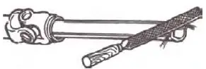
PTO Shaft Resizing
Safety:
Ensure the tractor & machine are stopped and keys are out of the ignition before carrying out any work. If you are not confident in carrying out the work, consult your local supplier or mechanic. Most PTO-driven implements are supplied with a standard-size PTO shaft. As all tractors vary, this often means cutting it down to size. Always replace worn or damaged PTO shafts.
Attach the machine to the tractor without the PTO shaft, and raise the linkage so the PTO shaft is level/horizontal. Measure the length between the tractor PTO and the machine’s shaft. If the compressed (closed PTO shaft length exceeds the one measured here then the driveline will need to be cut.
- PTO length adjustment, First remove shaft shielding

- Shorten the driveline tubes to proper equal lengths

- Tidy the edges of the drive tube with a file and clean all fillings from the tubes

- Shorten the equally long guard tubes to the same length as the driveline tubes

- Grease the internal driveline tube

- Fit the guard on the shaft

- Make sure that the length allows for at least 6 inches of overlap


Troubleshooting
| PROBLEM | SOLUTION |
| Belt Slipping | Clean the mower deck Adjust the belt tension Replace belts |
| Patches of uncut grass | Mow at 540 PTO rpm, Check PTO speed & tractor power output Change into a lower gear on the tractor Tighten Belts |
| Excessive Vibration | Replace belts Replace blades Align/replace belt pulleys Remove belt gaurd and clean debris from belt area Remove debris from rotor Check PTO shaft for damage and replace |
| Gearbox Noisy | Check oil level and top up if required Extract the oil/debris and replace with new oil |
| Blades Scalping | Raise cutting height Change mower pattern/route Reduce speed when turning |
| Uneven Cut | Change into a lower geaer on the tractor Level the mower using tractor linkage/hydraulics Replace any missing/damaged blades |
| Tractor Loaded Down by Mower | Mow at 540 PTO rpm Change into a lower gear on the tractor Clean off the mower Check the power output on your tractor |
PARTS REQUEST FORM
fax to 541-895-2756 or Email [email protected].
Comments:
Limited Warranty
FARMER-HELPER Limited Warranty
Unless otherwise stated on the purchase invoice, Betstco warrants to the original Purchaser that Farmer-Helper products are free from major effects in material under normal use and service for a period of 90 Days from the date the product is purchased or shipped, whichever is later. Commercial use 90 days. Use at the address that is not yours, is considered commercial use. Consumable, Expendable, Wear Items (Rubber plastic parts, hydraulic hoses, belts, tires, cables, blades, tines, wedges, teeth, tips, chains, pins, brushes, filters, etc) and cracked hydraulic pumps, bent or broken cylinders rods are not covered under this warranty. The warranty does not cover items that have been modified, damaged by abuse or usage, or not in accordance with design or maintenance.
Betstco’s obligation under this warranty is to repair or replace defective upon approval by; Betstco, 83371 Melton Rd. N, Creswell OR 97426 that Warranty Claim is valid. The product shall be returned upon request of Betstco. Transportation charges are to be prepaid by the user. Gasoline or diesel engines used to power Farmer-Helper products are covered by the warranty of the appropriate engine manufacturer Purchaser must look to the engine manufacturer for all issues relating to engine operation.
Betstco assumes no responsibility for outside labor
PERMISSIBLE BY APPLICABLE LAW, BETSTCO HEREBY DISCLAIMS ALL WARRANTIES OF ANY KIND, EITHER EXPRESS OR IMPLIED, INCLUDING, ANY IMPLIED WARRANTIES WITH RESPECT TO THE PRODUCT PURCHASED, WITHOUT LIMITING THE GENERALITY OF THE FOREGOING, BETSTCO HEREBY EXPRESSLY DISCLAIMS ALL LIABILITY FOR PRODUCT DEFECT OR FAILURE, CLAIMS THAT ARE DUE TO NORMAL WEAR, PRODUCT MISUSE, ABUSE, PRODUCT MODIFICATION, IMPROPER PRODUCT SELECTION, NON-COMPLIANCE WITH ANY CODES, OR MISAPPROPRIATION. BETSTCO MAKES NO WARRANTIES TO THOSE DEFINED AS “CONSUMERS” IN THE MAGNUSON-MOSS WARRANTY-FEDERAL TRADE COMMISSION IMPROVEMENTS ACT. THE FOREGOING EXCLUSION OF IMPLIED WARRANTIES DOES NOT APPLY TO THE EXTENT PROHIBITED BY LAW. PLEASE REFER TO YOUR LOCAL LAWS FOR ANY SUCH PROHIBITIONS.
THERE SHALL BE NO LIABILITY FOR PRODUCT LIABILITY OR LIABILITY ON THE PART OF BETSTCO FOR ANY GENERAL SPECIAL OR CONSEQUENTIAL DAMAGES ARISING OUT OF THE SALE OR USE OF ANY PRODUCTS SOLD BY BETSTCO OR AN AGENT THEREOF, BETSTCO MAKES NO WARRANTIES, EXPRESS OR IMPLIED, (INCLUDING, BUT NOT LIMITED TO, ANY WARRANTY OF MERCHANTABILITY OR FITNESS OF THE PRODUCTS FOR ANY PURPOSE) WITH RESPECT TO THE PRODUCTS COVERED BY THIS AGREEMENT EXCEPT AS IN THIS PARAGRAPH OTHERWISE EXPRESSLY PROVIDED.
THIS IS THE SOLE AND ONLY WARRANTY OF VALUE-LEADER PRODUCTS, NO OTHER WARRANTY IS APPLICABLE, EITHER EXPRESSED OR IMPLIED, IN FACT BY LAW. This warranty shall not be interpreted to render Betstco, or any authorized agent liable for injury or damages of any kind or nature, direct, consequential, or contingent, to a person or property.
The sole and only remedy in regard to any defective product shall be the repair or replacement thereof as herein provided, Betstco, agents) of Betstco shall not be liable for any consequential, special, incidental, or punitive damages resulting from or caused by any such defects Betstco reserves the rights to make improvements in design or changes in specifications at any time, without incurring any obligations to owners of the units previously sold.
WARRANTY VOID IF REGISTRATION IS NOT RECEIVED OR RECORDED ONLINE WITHIN 30 DAYS OF PURCHASE DATE OR SHIP DATE, WHICHEVER IS LATER.
- ITEM:
- MODEL#
- PURCHASE DATE:
- PURCHASED FROM:
- GIFT INV# ORDER#
- OWNER NAME:
- SERIAL #
- OWNER ADDRESS:
- CITY:
- COUNTY:
- ST:
- ZIP:
- PHONE:
- EMAIL:
ACCEPTANCE OF RESPONSIBILITY:
I (THE PURCHASER) HAVE READ THE OPERATOR MANUAL AND LIMITED WARRANTY OR SOMEONE HAS READ/AND EXPLAINED ALL INSTRUCTIONS TO ME. I UNDERSTAND THIS WARRANTY DOES NOT COVER ANY LABOR AND THAT ALL DISPUTES WILL BE SETTLED BY BINDING ARBITRATION. BINDING ARBITRATION IS CONDUCTED BY THE BETTER BUSINESS BUREAU (BBB) LOCATED AT 4004 SW KRUSE WAY PLACE ST 375 LAKE OSWEGO OR 97035 OR THE CURRENT BBB LOCATION CLOSEST TO BETSTCO. I ACKNOWLEDGE MY LIMITED WARRANTY IS VOID IF ANY ATTEMPT TO REPAIR OR REPLACE DEFECTIVE PARTS HAS BEEN MADE BY UNAUTHORIZED PERSONNEL.I ACKNOWLEDGE RECEIPT OF MY OPERATOR’S MANUAL AND HAVE READ THE SAFE OPERATION SECTION. I ACKNOWLEDGE UNDERSTANDING MAINTENANCE AND SAFE OPERATION REQUIREMENTS, ITEM SPECIFICATIONS, OPERATION, CONTROLS, AND STORAGE REQUIREMENTS. I UNDERSTAND THAT
IS ALONE AM RESPONSIBLE FOR THE PROPER MAINTENANCE, CARE, AND SAFE OPERATION OF THIS FARMER-HELPER ITEM
I (THE PURCHASER) AGREE THAT PERSONS NOT FAMILIAR WITH THE OPERATION OF THIS ITEM SHOULD NOT BE ALLOWED TO USE IT. CHILDREN ESPECIALLY SHOULD NOT OPERATE OR BE NEAR POWER PRODUCTS WHEN IN USE. ANYONE OPERATING VALUE-LEADER PRODUCTS SHOULD HAVE READ OPERATIONS MANUALS AND SAFETY MANUALS.
- OWNERS SIGNATURE: x
- DATE:
YOU MUST SIGN THIS WARRANTY AND MAIL OR FAX A COPY TO BETSTCO, 83371 MELTON RD, CRESWELL OR, 97426. IF YOU PREFER YOU MAY COMPLETE YOUR REGISTRATION ONLINE AT WWW.VALUE-LEADER.COM. THIS WARRANTY IS NOT EFFECTIVE UNLESS THE PURCHASER COMPLETES REGISTRATION AND WARRANTY FOR WITHIN 30 DAYS OF PURCHASE OR SHIP DATE WHICHEVER IS LATER.
NOTE:
WE MAY REFUSE WARRANTY OF ANY KIND UNLESS BETSTCO, RECEIVES A COMPLETED, LEGIBLE, AND SIGNED WARRANTY REGISTRATION. IT IS THE RESPONSIBILITY OF THE PURCHASER TO ASSURE THAT THE REGISTRATION DOCUMENT IS RECEIVED BY
1 YEAR EXTENDED WARRANTY & REGISTRATION FARMER-HELPER IMPLEMENTS BRANDED PRODUCTS1 YEAR EXTENDED WARRANTY
1 Year Extended Warranty amends to original Recorded Warranty Registration the time period of described coverage. Extended Warranty does not apply to consumable and Expendable Items as described in Product Warranty Registration.
This amendment does not affect any other part of the recorded Warranty Registration or policy. No one is authorized to alter, modify, or enlarge this Amendment to the original recorded Warranty Registration
EXTENDED REGISTRATION & PAYMENT MUST BE RECEIVED WITHIN 30 DAYS OF THE PURCHASE DATE
EXTENDED WARRANTY REGISTRATION
- PRODUCT & MODEL #
- SERIAL #
- OWNER NAME:
- BETSTCO INVOICE #
ACCEPTANCE OF RESPONSIBILITY:
I (THE PURCHASER) HAVE READ AND UNDERSTAND THE EXTENDED WARRANTY OR SOMEONE HAS READ AND EXPLAINED ALL THE ABOVE TO ME. I UNDERSTAND THIS EXTENDED WARRANTY DOES NOT COVER ANY LABOR. I HAVE FILED MY ORIGINAL WARRANTY REGISTRATION AND FULLY UNDERSTAND MY REQUIREMENTS. I UNDERSTAND THAT I ALONE AM RESPONSIBLE FOR THE PROPER MAINTENANCE, CARE, AND SAFE OPERATION OF THIS TRACTOR IMPLEMENT.
- OWNERS SIGNATURE: x
- DATE:
FAX TO 1-541-895-2756
YOU MUST SIGN THIS WARRANTY AND MAIL OR FAX A COPY TO BETSTCO, 83371 MELTON RD, CRESWELL OR. IF YOU PREFER YOU MAY COMPLETE YOUR REGISTRATION ONLINE AT WWW.VALUE-LEADER.COM. THIS WARRANTY IS NOT EFFECTIVE UNLESS THE PURCHASER COMPLETES REGISTRATION AND WARRANTY FOR WITHIN 30 DAYS OF PURCHASE OR SHIP DATE WHICHEVER IS LATER.
NOTE:
WE MAY REFUSE WARRANTY OF ANY KIND UNLESS BETSTCO, RECEIVES A COMPLETED, LEGIBLE, AND SIGNED WARRANTY REGISTRATION. IT IS THE RESPONSIBILITY OF THE PURCHASER TO ASSURE THAT THE REGISTRATION DOCUMENT IS RECEIVED BY BETSTCO.


