
SmartGen CMM366A-4G Cloud Monitoring Communication Module
- SmartGen — make your generator smart
- SmartGen Technology Co., Ltd.
- No.28 Jinsuo Road Zhengzhou Henan Province P. R. China
- Tel:
+86-371-67988888/67981888/67992951
+86-371-67981000 (overseas) - Fax: +86-371-67992952
- Web:
www.smartgen.com.cn/
www.smartgen.cn/ - Email: [email protected]
- All rights reserved. No part of this publication may be reproduced in any material form (including photocopying or storing in any medium by electronic means or other) without the written permission of the copyright holder.
- Applications for the copyright holder’s written permission to reproduce any part of this publication should be addressed to SmartGen Technology at the address above.
Any reference to trademarked product names used within this publication is owned by their respective companies. - SmartGen Technology reserves the right to change the contents of this document without prior notice.
Table 1 – Software Version
| Date | Version | Note |
| 2017-12-25 | 1.0 | Original release. |
| 2022-07-14 | 1.1 | Update company logo and manual format. |
OVERVIEW
CMM366A-4G Cloud Monitoring Communication Module is 4G GPRS wireless network communication protocol switch module which can achieve genset (with SCI) connect to Internet. After logging into cloud server, module will receive corresponding genset controller communication protocol from cloud server. And the module gains genset data via RS485 port, USB port, LINK port or RS232 port. Then the module transmits the data to corresponding cloud server via 4G wireless network for achieving user’s real-time monitoring to running status and searching of running records via APP (IOS or Android) and pc terminal devices.
CMM366A-4G module not only can achieve genset monitoring but also can insert some digital alarm input/output signal to achieve monitoring of generator room entrance guard, guard against theft and fire facilities.
CMM366A-4G module, which has GPS locate function, can upload gained longitude, latitude and altitude to corresponding cloud server.
PERFORMANCE AND CHARACTERISTICS
- Connect to cloud server via 4G wireless network , one to one
- Multiple ports for communication with genset control module: RS485, RS232, LINK and USB (Host); can monitor great majority genset control modules of inte rnational first-class brands;
- Widely power supply: DC (8~35)V, can direct use genset buil t in battery;
- With ARM based 32 bit SCM, high integration of hardware and strong programming ability;
- Include with GPS locate function to achieve gain location informa tion and locate genset
- Take JSON network data communication protocol, upload real time data variation and take compression algorithm to vastly reduce network flow at the same time;
- When alarm occurs it can upload data to server immediately;
- 2 auxiliary di gital input ports which can receive external alarm signal;
- 1 auxiliary relay output ports which can output various of alarm signal;
- Power and multiple communication status indicators on front panel that working status is clear at a glance;
- Lamp test functi on;
- Parameter adjust function: users can adjust parameters via USB port;
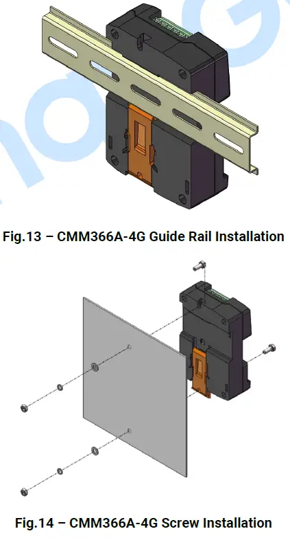
- Take standard π type 35mm guide rail installation or screw fixed installation that the module can be installed in the genset control box;
- Modular design, self extinguishing ABS plasti c shell, light weight, compact structure with easy installation
SPECIFICATION
Table 2 Technical Data
| Items | Contents |
| Operating Voltage | DC 8.0V~35.0V, continuous power supply. |
| Power Consumption | Standby: ≤2W Working: ≤5W |
| Digital Input | Digital Input, connect (B-) is active. |
| Relay Output | 1A DC30V Volts free output |
| USB Host | A-type USB female port |
| RS485 | Isolated type |
| RS232 | General type |
| LINK | SmartGen exclusive port |
| USB Device | B-type USB female port |
| GPRS Port | Standard SMA port (female), SMA port (male) for antenna |
| GPS Port | Standard SMA port (female), SMA port (male) for antenna, active antenna |
| Wireless Network | LTE-TDD/LTE-FDD/HSPA+/TD-SCDMA/EVDO GSM/GPRS/EDGE |
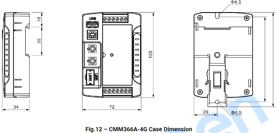
| Case Dimensions | 72.5mmx105mmx34mm |
| Working Temperature | (-25~+70)°C |
| Working Humidity | (20~93)%RH |
| Storage Temperature | (-25~+70)°C |
| Weight | 0.15kg |
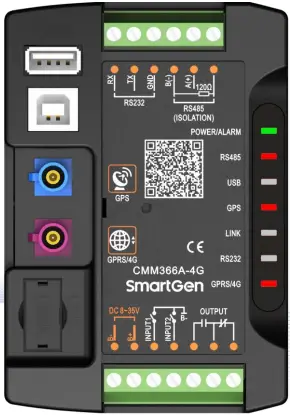
PANEL AND TERMINAL DESCRIPTION
PANEL INDICATOR AND BUTTONS
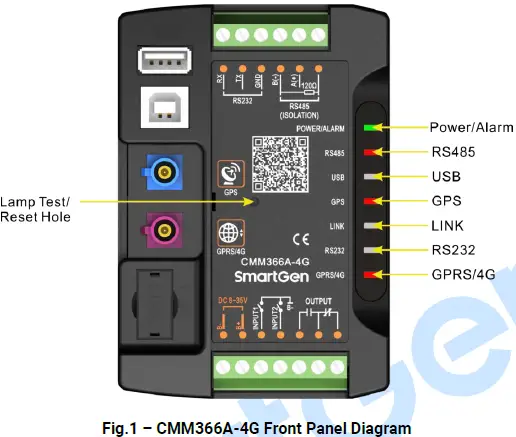 Indicators Description
| Icon | Note |
| POWER/ALARM | Green LED Light: Power supply normal indicator; Red LED Light: Common alarm indicator. |
| RS485(Red) | Normally Extinguish: RS485 disabled; Normally Light: Communication fail; Blink: Communication normal. |
| USB(Red) | Normally Extinguish: USB(Host) disabled; Normally Light: Communication fail; Blink: Communication normal. |
| GPS(Red) | Normally Extinguish: GPS disabled; Normally Light: GPS not gained satellite signal; Blink: GPS gained satellite signal. |
| LINK(Red) | Normally Extinguish: Disabled; Normally Light: Communication fail; Blink: Communication normal. |
| RS232(Red) | Normally Extinguish: RS232 disabled; Normally Light: Communication fail; Blink: Communication normal. |
| GPRS/4G(Red) | Extinguish: CMM366A-4G login with server unsuccessfully; Light: Login with server successfully; Blink: Real-time communication normal. |
Internal Lamp test/Reset Key:
Press it for 1s, all the LEDs are illuminated; press it for 10s, reset the module to default and all the LEDs blink for 3 times
NOTE: After reset the module, parameters need to be re-configured via PC software. Please operate cautiously.
GPRS
Connect GPRS antenna to GPR S 4 G port.
Antenna: 50Ω/SMA female.
GPS
GPS enabled, connect GPS antenna to CMM366 A 4 G.
NOTE
: GPS antenna needs to be placed to open outdoors, otherwise location information may not accurate or cannot be gain ed.
Antenna:
50Ω/SMA female, active antenna.
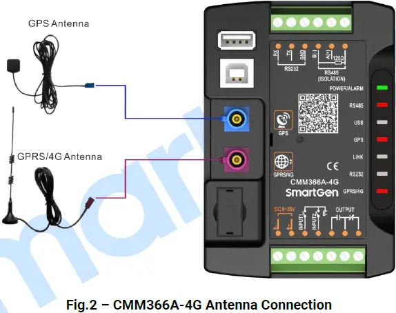
NOTE
GPRS antenna and GPS antenna cannot be connected reversely.
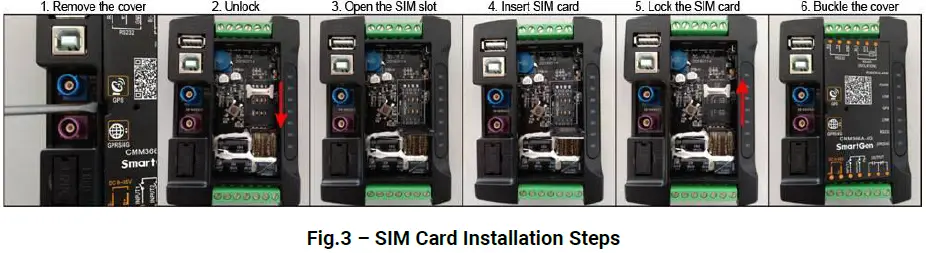
SIM INSTALLATION
Insert 4G, 3G or 2G SIM card. C MM366 A 4 G will connect to servers via wireless mobile network.
NOTE: 4G GPRS wireless network is supported. Use standard SIM card (25mmX15mm); GPS indicator and GPRS indicator blink in the same time, which means SIM card hasn’t been inserted or bad contacts. After removing the head cover , the installation steps are as
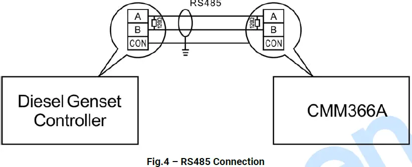
RS485
Receive genset data information by connecting module RS485 port with Genset Controller RS485 port.
If communication is abnormal, 120Ω terminal resistance is recommonded. One end of shield wire hangs in the air and the other one connects with SCR.
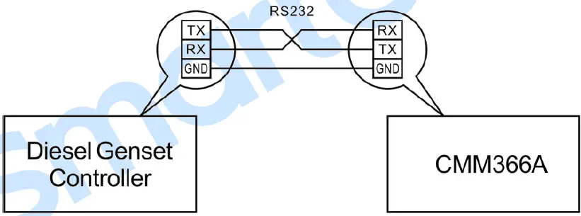
RS232
Receive genset data information by connecting module RS232 port with Genset Controller RS232
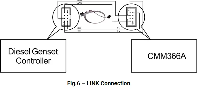
LINK
Receive genset data information by connecting module LINK port with Genset Controller LINK port
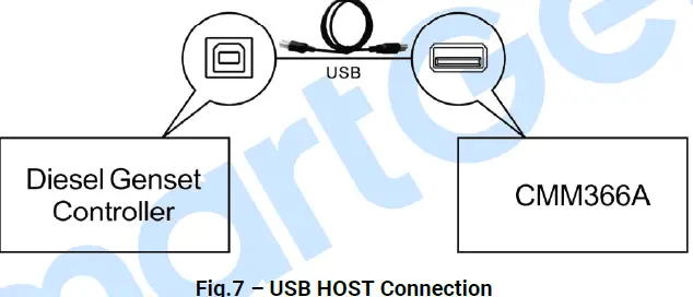
USB HOST
Receive genset data information by connecting module A-type USB port (female port) with Genset Controller USB port via USB cable
USB DEVICE
All the parameters can be configured and view CMM366A-4G ID&Login password by connecting USB port with USB disk of PC software
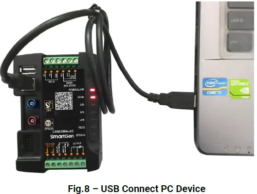
Table 4 – Terminals Description
| No. | Function | Cable Size | Note | |
| 1 | B- | 1.0mm2 | Connected with negative of starter battery. | |
| 2 | B+ | 1.0mm2 | Connected with positive of starter battery. 3A fuse is recommended. | |
| 3 | Digital Input 1 | 1.0mm2 | Active when connect to B-. | |
| 4 | Digital Input 2 | 1.0mm2 | Active when connect to B-. | |
| 5 |
Relay Output | Normally Open | 1.0mm2 |
Volt free output with 1A DC30V. |
| 6 | Common | 1.0mm2 | ||
| 7 | Normally Close | 1.0mm2 | ||
| 8 | RS485 B(-) | 0.5mm2 | Impedance-120Ω shielding wire is recommended, its single-end earthed. | |
| 9 | RS485 A(+) | 0.5mm2 | ||
| 10 | RS485 (SCR) | 0.5mm2 | ||
| 11 | RS232 RX | 0.5mm2 | RS232 port. | |
| 12 | RS232 TX | 0.5mm2 | ||
| 13 | RS232 GND | 0.5mm2 | ||
PROGRAMMABLE PARAMETERS
CONTENTS AND SCOPES OF PARAM ETERS
Table 5 Parameter Content & Scope
| No. | Items | Parameters | Defaults | Description | |
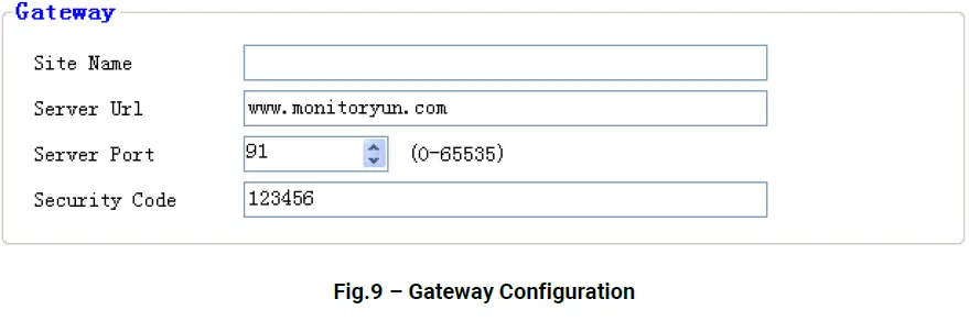
| Gateway | |||||
| 1 | Site Name | (0-65535) | 20 Chinese characters, letters or numbers | ||
| 2 | URL | (0-65535) | www.monitoryun.com | 40 characters | |
| 3 | Server Port | (0-65535) | 91 | ||
| 4 | Security Code | (0-65535) | 123456 | 16 characters | |
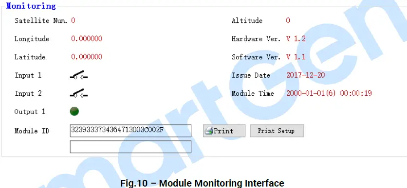
| GPS | |||||
| 1 | GPS Enabled | (0-1) | 1 | 0: Manual Input 1: GPS Location | |
| 2 | Longitude | ((-180)-180)° | 0.000000 | GPS location, altitude information | |
| 3 | Latitude | ((-90)-90)° | 0.000000 | ||
| 4 | Altitude | ((-9999.9)-9999.9)m | 100.0 | ||
| GSM | |||||
| 1 | GSM Enabled | (0-1) | 1 | 0: Disabled; 1: Enabled | |
| 2 | GPRS Password | Reserved | |||
| 3 | Message Center | Reserved | |||
| 4 | PIN Enabled | (0-1) | 0 | 0: Disabled; 1: Enabled | |
| 5 | APN | (0-65535) | 40 characters | ||
| Digital Input | |||||
| Digital Input 1 | |||||
| 1 | Setting | (0-9) | 0 | Default: Not used | |
|
2 |
Type |
(0-1) |
0 | 0: Active when close 1: Active when open See: Table 6 – Digital Input Ports Content | |
| 3 | Delay | (0-20.0) | 0.0 | Action delay | |
| Digital Input 2 | |||||
| 1 | Setting | (0-9) | 1 | Default: Lamp test | |
|
2 |
Type |
(0-1) |
0 | 0: Active when close 1: Active when open See: Table 6 – Digital Input Ports Content | |
| 3 | Delay | (0-20.0) | 0.0 | Action delay | |
| Digital Output | |||||
| 1 | Setting | (0-14) | 0 | Default: Not used See: Table 7 – Relay Output Ports Content | |
Table Digital Input Ports Content
| No. | Item | Description |
| 0 | Not Used | Not used. |
| 1 | Lamp Test | All the indicators are illuminated when input is active. |
| 2 | Remote Control Inhibited | Cloud start/stop control is prohibited when input is active. |
| 3 | Access Alarm Input | Access alarm is uploaded to server when input is active. |
| 4 | Fire Alarm Input | Fire alarm is uploaded to server when input is active. |
| 5 | Alarm Input | External alarm is uploaded to server when input is active. |
| 6 | Reserved | |
| 7 | Reserved | |
| 8 | Reserved | |
| 9 | Factory Test Mode | It is only used for factory test when active. |
Table 7 – Relay Output Ports Content
| No. | Item | Description |
| 0 | Not used | Output port won’t output when this item is selected. |
| 1 | Digital Input 1 Active | Output when auxiliary input 1 is active. |
| 2 | Digital Input 2 Active | Output when auxiliary input 2 is active. |
| 3 | RS485 Comm. Fail | Output when RS485 communication fails. |
| 4 | Network Comm. Fail | Output when Network communication fails. |
| 5 | LINK Comm. Fail | Output when LINK communication fails. |
| 6 | RS232 Comm. Fail | Output when RS232 communication fails. |
| 7 | Common Alarm | Output when there is an alarm. |
| 8 | Remote Control Output | Send remote control commands via cloud platform with fixed output delay 20s. |
| 9 | Reserved | |
| 10 | Reserved | |
| 11 | Reserved | |
| 12 | Reserved | |
| 13 | Reserved | |
| 14 | Reserved |
PC CONFIGURATION INTERFACE
Connecting the USB port of CMM366A-4G communication module with PC USB port to configure the parameters.
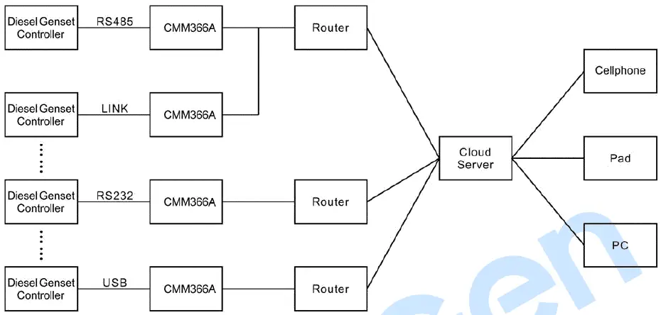
SYSTEM DIAGRAM
One CMM 366 A 4 G module connects with one genset monitor module . It can be connected via RS485 port, LINK port, RS232 port or USB port.
CASE DIMENSION AND INSTALLATION
2 ways for installation: 35mm guide rail in box or screw (M4) installation as below:
FAULT FINDING
Table 8 Fault Finding
| Symptoms | Possible Solutions |
| Controller No Response for Power | Check power voltage; Check controller connection wirings. |
| GPRS/4G Indicator Not Light | Check SIM card is inserted or not; Check GPRS antenna is connected or not. |
| GPS Not Gain Location | Check GPS parameters are enabled or not; Check GPS antenna is connected or not and placed outdoor or not. |
|
RS485 Comm. Abnormal | Check connections; Check RS485 port is enabled or not; Check settings of genset ID and baud rate are correct or not. Check RS485’s connections of A and B is reverse connect or not. |
| RS232 Comm. Abnormal | Check connections; Check RS232 port is enabled or not; Check settings of genset ID and baud rate are correct or not. |
| LINK Comm. Abnormal | Check connections; Check LINK port is enabled or not; Check settings of genset ID and baud rate are correct or not. |
PACKING LIST
Table 9 Packing List
| No. | Name | Quantity | Remark |
| 1 | CMM366A-4G | 1 | |
| 2 | Osculum type GSM antenna | 1 | |
| 3 | External GPS antenna | 1 | |
| 4 | Certificate | 1 | |
| 5 | User manual | 1 |
CMM366A-4G Cloud Monitoring Communication Module User Manual


